EP0732468B1 - Becken oder Wassertank, wie z.B. ein Schwimmbad, mit Mitteln zum Erzeugen von Wellen - Google Patents
Becken oder Wassertank, wie z.B. ein Schwimmbad, mit Mitteln zum Erzeugen von Wellen Download PDFInfo
- Publication number
- EP0732468B1 EP0732468B1 EP95200534A EP95200534A EP0732468B1 EP 0732468 B1 EP0732468 B1 EP 0732468B1 EP 95200534 A EP95200534 A EP 95200534A EP 95200534 A EP95200534 A EP 95200534A EP 0732468 B1 EP0732468 B1 EP 0732468B1
- Authority
- EP
- European Patent Office
- Prior art keywords
- pool
- tank
- pipe
- wave
- piston
- Prior art date
- Legal status (The legal status is an assumption and is not a legal conclusion. Google has not performed a legal analysis and makes no representation as to the accuracy of the status listed.)
- Expired - Lifetime
Links
Images

Classifications
-
- E—FIXED CONSTRUCTIONS
- E04—BUILDING
- E04H—BUILDINGS OR LIKE STRUCTURES FOR PARTICULAR PURPOSES; SWIMMING OR SPLASH BATHS OR POOLS; MASTS; FENCING; TENTS OR CANOPIES, IN GENERAL
- E04H4/00—Swimming or splash baths or pools
- E04H4/0006—Devices for producing waves in swimming pools
Definitions
- the invention relates to a wave installation for generating waves in a pool or water tank, comprising a conduit connected, at least at both ends, via a hole in the wall of pool or tank to the pool or tank, piston means essentially closing off the cross-section of the conduit, and a power source in order to move the piston means backwards and forwards.
- One of said methods comprises supplying compressed air in turn to chambers which are closed at the top and at the bottom protrude into the water in the pool or tank. If the compressed air is introduced into the various chambers at the natural frequency of the pool, this method requires relatively little energy, but the major drawback is that the tank or swimming pool has to have an adapted, relatively expensive design.
- a ball which has a weight which is movable up and down therein floats in the middle of the tank.
- a ball of this type takes up a relatively large amount of space and must be able to be suspended from the ceiling by a hoist construction.
- a long electric cable to the ball is needed underwater, the length of said cable being subject to regulations. Further the ball is a heavy weight and may hurt people during movement.
- DE-A-2811623 describes a swimming pool wherein a niche filled with water joins one of the sides of the swimming pool is in open communication with the swimming pool and is divided into three chambers by means of two partitions.
- the two partitions are each connected by means of a rod to a piston which is movable in a hydraulic cylinder. Waves can be generated in the swimming pool by moving the two partitions by means of the pistons.
- This construction requires expensive structural facilities and is not suitable for adding to an existing swimming pool as a recreation element in a simple manner.
- the aim of the invention is to overcome the drawbacks of known wave installations and to provide a wave installation indicated in the preamble, for which the means for generating waves are simple and relatively inexpensive and can be installed in existing pools or tanks without special structural facilities (apart from possibly raising the hight of the walls of the pool or tank). Moreover, the wave facilities must not give rise to obstacles for swimmers and there must be no cables or leads present in the pool or tank.
- the wave installation is characterized in that said conduit consists of one single pipe not belonging to the building structure of the pool or tank, and that said pipe is divided by one single piston into two flow chambers.
- the length of the pipe corresponds to at most half of the resonance wave length of the water in the pool or tank.
- each pipe will be provided on the other side of a central section, in which said piston is movable, with two or more channels connected to a hole in the wall of the swimming pool.
- the cross-sectional area of the channels will have to be greatest at locations where the amplitude of the wave is greatest, and visa versa. Therefore, the cross-sectional area of the channels will be greatest at the ends of the pipe and that of the channels at the side of the means will be smallest and the cross-sectional area of the channels will decrease from the largest channel to the smallest channel.
- the power sources will operate in phase with one another and adjacent pipes will have opposing directions of flow.
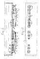
- the walls of the wave pool or tank shown are indicated by 1.
- Two wave installations each consisting of a pipe 2 having a central section 3 and two connecting sections 4 fitted on either side thereof, are installed on one side wall.
- the connecting sections 4 each have three inlet and outlet channels 7a, 7b, 7c, which are connected by flange connections to openings 8a, 8b, 8c in the side wall of the pool or tank.
- Figure 3 shows the flange connection between a channel 7a and the side wall of the pool or tank.
- a pipe 9 is fixed by means of resin in the opening 8a to provide a seal.
- Said pipe has a flange 10, which is fixed by means of bolts 11 to a flange 12 of the channel 7a.
- the length of a pipe 2 corresponds to at most half the resonance wavelength of the pool or tank.
- the two pipes shown generate waves which have twice a half resonance wavelength.
- the one pipe operates in the same phase but in the reverse direction of flow to the preceding pipe.
- the shape of the waves is shown by a broken line in Figure 2.
- the channels 7a and the openings 8a at the ends of a pipe 2 have a larger cross-section than the channels 7b and openings 8b, which, in turn, have a larger cross-section than the channels 7c and openings 8c. Consequently, the size of the cross-section follows the size of the wave amplitude.
- the first impulse will take a great deal of power, but as the wavelength of the generated wave follows the resonance wavelength of the pool or water tank, it becomes increasingly easier.
- the installation according to the invention has considerable advantages. It is easy to install. No structural facilities are needed for wave generation. It may be necessary to raise the height of the sides of the pool or tank, or the water level could be lowered.
- the apparatus can be fixed to the outside of existing pools or tanks by simply drilling a few holes in the wall of the pool or tank. The apparatus does not constitute any obstacles for the swimmer and there are no cables or leads through the area. It is very suitable for use in tanks containing mammals or fish and produces no noise.
Landscapes
- Engineering & Computer Science (AREA)
- Architecture (AREA)
- Civil Engineering (AREA)
- Structural Engineering (AREA)
- Other Liquid Machine Or Engine Such As Wave Power Use (AREA)
- Devices For Medical Bathing And Washing (AREA)
- Aerodynamic Tests, Hydrodynamic Tests, Wind Tunnels, And Water Tanks (AREA)
Claims (6)
- Welleneinrichtung zum Erzeugen von Wellen in einem Pool oder Wassertank, umfassend eine Leitung (2), die zumindest an beiden Enden über ein Loch (8) in der Wand eines Pools oder Tanks mit dem Pool oder Tank verbunden ist, eine Kolbeneinrichtung (5), die im wesentlichen den Querschnitt der Leitung abschließt, und eine Energiequelle (6), um die Kolbeneinrichtung nach hinten und nach vorne zu bewegen,
dadurch gekennzeichnet, daß die Leitung aus einer einzelnen Röhre besteht, die nicht zu dem Aufbau des Pools oder Tanks gehört, und daß die Röhre durch einen einzelnen Kolben in zwei Strömungskanäle unterteilt ist. - Welleneinrichtung gemäß Anspruch 1, dadurch gekennzeichnet, daß die Länge der Röhre (2) höchstens der Hälfte der Resonanzwellenlänge des Wassers in dem Pool oder Tank entspricht.
- Welleneinrichtung gemäß Anspruch 1 oder 2, dadurch gekennzeichnet, daß die Röhre (2) auf der anderen Seite des mittleren Abschnittes (3) vorgesehen ist, in dem der Kolben bewegbar ist, mit zwei oder mehreren Kanälen (7a, 7b, 7c), die mit einem Loch (8a, 8b, 8c) in der Wand des Swimmingpools verbunden sind.
- Welleneinrichtung gemäß Anspruch 3, dadurch gekennzeichnet, daß der Querschnittsbereich der Kanäle (7a) am Ende der Röhre am größten ist und daß der Kanal (7c) an der Seite des mittleren Abschnittes (3) am kleinsten ist und jegliche Kanäle (7b) bezüglich der Querschnittsfläche vom größten Kanal zum kleinsten Kanal abnehmen.
- Pool oder Tank, umfassend eine oder mehrere Welleneinrichtungen gemäß einem der vorhergehenden Ansprüche.
- Pool oder Tank gemäß Anspruch 5, dadurch gekennzeichnet, daß, wenn verschiedene Röhren (2) verwendet werden, die Leistungsquellen (5) miteinander in Phase arbeiten, jedoch in entgegengesetzten Strömungsrichtungen.
Priority Applications (3)
| Application Number | Priority Date | Filing Date | Title |
|---|---|---|---|
| AT95200534T ATE176024T1 (de) | 1995-03-03 | 1995-03-03 | Becken oder wassertank, wie z.b. ein schwimmbad, mit mitteln zum erzeugen von wellen |
| EP95200534A EP0732468B1 (de) | 1995-03-03 | 1995-03-03 | Becken oder Wassertank, wie z.B. ein Schwimmbad, mit Mitteln zum Erzeugen von Wellen |
| DE69507449T DE69507449T2 (de) | 1995-03-03 | 1995-03-03 | Becken oder Wassertank, wie z.B. ein Schwimmbad, mit Mitteln zum Erzeugen von Wellen |
Applications Claiming Priority (1)
| Application Number | Priority Date | Filing Date | Title |
|---|---|---|---|
| EP95200534A EP0732468B1 (de) | 1995-03-03 | 1995-03-03 | Becken oder Wassertank, wie z.B. ein Schwimmbad, mit Mitteln zum Erzeugen von Wellen |
Publications (2)
| Publication Number | Publication Date |
|---|---|
| EP0732468A1 EP0732468A1 (de) | 1996-09-18 |
| EP0732468B1 true EP0732468B1 (de) | 1999-01-20 |
Family
ID=8220066
Family Applications (1)
| Application Number | Title | Priority Date | Filing Date |
|---|---|---|---|
| EP95200534A Expired - Lifetime EP0732468B1 (de) | 1995-03-03 | 1995-03-03 | Becken oder Wassertank, wie z.B. ein Schwimmbad, mit Mitteln zum Erzeugen von Wellen |
Country Status (3)
| Country | Link |
|---|---|
| EP (1) | EP0732468B1 (de) |
| AT (1) | ATE176024T1 (de) |
| DE (1) | DE69507449T2 (de) |
Families Citing this family (3)
| Publication number | Priority date | Publication date | Assignee | Title |
|---|---|---|---|---|
| BE1011083A6 (fr) | 1997-04-03 | 1999-04-06 | Inan Mehmet Zahit | Generateur de vagues pour liquides. |
| US9920544B1 (en) | 2016-11-29 | 2018-03-20 | Walter Judson Bennett | Plunger wave generator apparatus for efficiently producing waves in a body of water |
| AU2019313161B2 (en) * | 2018-07-31 | 2021-08-26 | Liquid Time Ltd | Current control systems and wave pools including same |
Family Cites Families (4)
| Publication number | Priority date | Publication date | Assignee | Title |
|---|---|---|---|---|
| FR438113A (fr) * | 1911-12-02 | 1912-05-08 | Hermann Recknagel | Procédé et appareils pour la production de vagues artificielles |
| US3350724A (en) * | 1964-07-07 | 1967-11-07 | Walter J Leigh | Method and apparatus for generating artificial waves in a body of water |
| DE2811623A1 (de) * | 1978-03-17 | 1979-09-20 | Boehm Hans Joachim Dipl Ing | Wellenerzeugungsanlage fuer schwimmbaeder mit horizontal hin- und herbewegten trennwaenden in einem dreikammersystem |
| BE1002884A6 (fr) * | 1989-03-03 | 1991-07-16 | Servilog Sa | Appareil destine a creer des vagues dans des piscines. |
-
1995
- 1995-03-03 AT AT95200534T patent/ATE176024T1/de not_active IP Right Cessation
- 1995-03-03 DE DE69507449T patent/DE69507449T2/de not_active Expired - Fee Related
- 1995-03-03 EP EP95200534A patent/EP0732468B1/de not_active Expired - Lifetime
Also Published As
| Publication number | Publication date |
|---|---|
| DE69507449D1 (de) | 1999-03-04 |
| EP0732468A1 (de) | 1996-09-18 |
| DE69507449T2 (de) | 1999-06-02 |
| ATE176024T1 (de) | 1999-02-15 |
Similar Documents
| Publication | Publication Date | Title |
|---|---|---|
| US5621925A (en) | Pool or water tank, such as a swimming pool, provided with means generating waves | |
| JP7054210B2 (ja) | 海上構造物の据え付けや搬送のための補助浮き装置、およびその装置を備える方法 | |
| CA2146017A1 (en) | A device for a buoy-based wave power apparatus | |
| KR20030036643A (ko) | 풍력터빈을 해양에 설치하기 위한 부유구조물 | |
| CN109537631B (zh) | 一种自潜悬浮式水下隧道装置 | |
| GB2114636A (en) | Working chamber | |
| EP0732468B1 (de) | Becken oder Wassertank, wie z.B. ein Schwimmbad, mit Mitteln zum Erzeugen von Wellen | |
| CN113513005A (zh) | 海上浮岛 | |
| US3289419A (en) | Sea raft | |
| US4037425A (en) | Buoyancy apparatus | |
| EP0808391A1 (de) | Vorrichtung zur erzeugung einer lokalen wasserströmung | |
| CA2143884C (en) | Pool or water tank, such as a swimming pool provided with means for generating waves | |
| MXPA97006713A (en) | Wave generator for poolor tank | |
| GB2039330A (en) | Energy conversion devices | |
| KR101444311B1 (ko) | 부력이 조절되는 파이프라인 | |
| CN117755454A (zh) | 一种智能化船坞引船系统 | |
| KR20190109218A (ko) | 파고 조절 장치 | |
| WO2019177323A1 (ko) | 파고 조절 장치 | |
| EP0532079B1 (de) | Schwimmbecken mit einstellbarem Zwischenboden | |
| JPH0748851A (ja) | 水中トンネル | |
| CN115142463A (zh) | 一种海上浮体平台下悬挂的海中交通轨道的建造方法 | |
| RU2144968C1 (ru) | Устройство для преобразования потенциальной энергии мирового океана в электрическую энергию, выравниватель давления воды для энергетического блока глубинной гидроэлектростанции, монтажно-установочный комплекс для сборки этого блока и испытательный стенд для проверки работоспособности выравнивателя давления воды | |
| CN112644653A (zh) | 一种深远海半潜升降式hdpe多层平台 | |
| CN111094124A (zh) | 水运工具 | |
| CA2083646A1 (en) | Semisubmersible building |
Legal Events
| Date | Code | Title | Description |
|---|---|---|---|
| PUAI | Public reference made under article 153(3) epc to a published international application that has entered the european phase |
Free format text: ORIGINAL CODE: 0009012 |
|
| AK | Designated contracting states |
Kind code of ref document: A1 Designated state(s): AT BE CH DE DK ES FR GB GR IE IT LI LU MC NL PT SE |
|
| 17P | Request for examination filed |
Effective date: 19970124 |
|
| 17Q | First examination report despatched |
Effective date: 19970313 |
|
| GRAG | Despatch of communication of intention to grant |
Free format text: ORIGINAL CODE: EPIDOS AGRA |
|
| GRAG | Despatch of communication of intention to grant |
Free format text: ORIGINAL CODE: EPIDOS AGRA |
|
| GRAH | Despatch of communication of intention to grant a patent |
Free format text: ORIGINAL CODE: EPIDOS IGRA |
|
| GRAH | Despatch of communication of intention to grant a patent |
Free format text: ORIGINAL CODE: EPIDOS IGRA |
|
| GRAA | (expected) grant |
Free format text: ORIGINAL CODE: 0009210 |
|
| AK | Designated contracting states |
Kind code of ref document: B1 Designated state(s): AT BE CH DE DK ES FR GB GR IE IT LI LU MC NL PT SE |
|
| PG25 | Lapsed in a contracting state [announced via postgrant information from national office to epo] |
Ref country code: SE Free format text: THE PATENT HAS BEEN ANNULLED BY A DECISION OF A NATIONAL AUTHORITY Effective date: 19990120 Ref country code: LI Free format text: LAPSE BECAUSE OF FAILURE TO SUBMIT A TRANSLATION OF THE DESCRIPTION OR TO PAY THE FEE WITHIN THE PRESCRIBED TIME-LIMIT Effective date: 19990120 Ref country code: IT Free format text: LAPSE BECAUSE OF FAILURE TO SUBMIT A TRANSLATION OF THE DESCRIPTION OR TO PAY THE FEE WITHIN THE PRE;WARNING: LAPSES OF ITALIAN PATENTS WITH EFFECTIVE DATE BEFORE 2007 MAY HAVE OCCURRED AT ANY TIME BEFORE 2007. THE CORRECT EFFECTIVE DATE MAY BE DIFFERENT FROM THE ONE RECORDED.SCRIBED TIME-LIMIT Effective date: 19990120 Ref country code: GR Free format text: LAPSE BECAUSE OF NON-PAYMENT OF DUE FEES Effective date: 19990120 Ref country code: FR Free format text: LAPSE BECAUSE OF FAILURE TO SUBMIT A TRANSLATION OF THE DESCRIPTION OR TO PAY THE FEE WITHIN THE PRESCRIBED TIME-LIMIT Effective date: 19990120 Ref country code: ES Free format text: THE PATENT HAS BEEN ANNULLED BY A DECISION OF A NATIONAL AUTHORITY Effective date: 19990120 Ref country code: CH Free format text: LAPSE BECAUSE OF FAILURE TO SUBMIT A TRANSLATION OF THE DESCRIPTION OR TO PAY THE FEE WITHIN THE PRESCRIBED TIME-LIMIT Effective date: 19990120 |
|
| REF | Corresponds to: |
Ref document number: 176024 Country of ref document: AT Date of ref document: 19990215 Kind code of ref document: T |
|
| REG | Reference to a national code |
Ref country code: CH Ref legal event code: EP |
|
| REG | Reference to a national code |
Ref country code: IE Ref legal event code: FG4D |
|
| PG25 | Lapsed in a contracting state [announced via postgrant information from national office to epo] |
Ref country code: LU Free format text: LAPSE BECAUSE OF NON-PAYMENT OF DUE FEES Effective date: 19990303 |
|
| REF | Corresponds to: |
Ref document number: 69507449 Country of ref document: DE Date of ref document: 19990304 |
|
| PG25 | Lapsed in a contracting state [announced via postgrant information from national office to epo] |
Ref country code: IE Free format text: LAPSE BECAUSE OF NON-PAYMENT OF DUE FEES Effective date: 19990320 |
|
| PG25 | Lapsed in a contracting state [announced via postgrant information from national office to epo] |
Ref country code: PT Free format text: LAPSE BECAUSE OF FAILURE TO SUBMIT A TRANSLATION OF THE DESCRIPTION OR TO PAY THE FEE WITHIN THE PRESCRIBED TIME-LIMIT Effective date: 19990420 Ref country code: DK Free format text: LAPSE BECAUSE OF FAILURE TO SUBMIT A TRANSLATION OF THE DESCRIPTION OR TO PAY THE FEE WITHIN THE PRESCRIBED TIME-LIMIT Effective date: 19990420 |
|
| PG25 | Lapsed in a contracting state [announced via postgrant information from national office to epo] |
Ref country code: DE Free format text: LAPSE BECAUSE OF FAILURE TO SUBMIT A TRANSLATION OF THE DESCRIPTION OR TO PAY THE FEE WITHIN THE PRESCRIBED TIME-LIMIT Effective date: 19990421 |
|
| EN | Fr: translation not filed | ||
| REG | Reference to a national code |
Ref country code: CH Ref legal event code: PL |
|
| PG25 | Lapsed in a contracting state [announced via postgrant information from national office to epo] |
Ref country code: MC Free format text: LAPSE BECAUSE OF NON-PAYMENT OF DUE FEES Effective date: 19990930 |
|
| PLBE | No opposition filed within time limit |
Free format text: ORIGINAL CODE: 0009261 |
|
| STAA | Information on the status of an ep patent application or granted ep patent |
Free format text: STATUS: NO OPPOSITION FILED WITHIN TIME LIMIT |
|
| 26N | No opposition filed | ||
| REG | Reference to a national code |
Ref country code: IE Ref legal event code: MM4A |
|
| PGFP | Annual fee paid to national office [announced via postgrant information from national office to epo] |
Ref country code: AT Payment date: 20010323 Year of fee payment: 7 |
|
| REG | Reference to a national code |
Ref country code: GB Ref legal event code: IF02 |
|
| PGFP | Annual fee paid to national office [announced via postgrant information from national office to epo] |
Ref country code: GB Payment date: 20020227 Year of fee payment: 8 |
|
| PG25 | Lapsed in a contracting state [announced via postgrant information from national office to epo] |
Ref country code: AT Free format text: LAPSE BECAUSE OF NON-PAYMENT OF DUE FEES Effective date: 20020303 |
|
| PGFP | Annual fee paid to national office [announced via postgrant information from national office to epo] |
Ref country code: NL Payment date: 20020331 Year of fee payment: 8 |
|
| PGFP | Annual fee paid to national office [announced via postgrant information from national office to epo] |
Ref country code: DE Payment date: 20020402 Year of fee payment: 8 |
|
| PGFP | Annual fee paid to national office [announced via postgrant information from national office to epo] |
Ref country code: BE Payment date: 20020404 Year of fee payment: 8 |
|
| PG25 | Lapsed in a contracting state [announced via postgrant information from national office to epo] |
Ref country code: GB Free format text: LAPSE BECAUSE OF NON-PAYMENT OF DUE FEES Effective date: 20030303 |
|
| PG25 | Lapsed in a contracting state [announced via postgrant information from national office to epo] |
Ref country code: BE Free format text: LAPSE BECAUSE OF NON-PAYMENT OF DUE FEES Effective date: 20030331 |
|
| BERE | Be: lapsed |
Owner name: *BASTENHOF DIRK Effective date: 20030331 |
|
| PG25 | Lapsed in a contracting state [announced via postgrant information from national office to epo] |
Ref country code: NL Free format text: LAPSE BECAUSE OF NON-PAYMENT OF DUE FEES Effective date: 20031001 |
|
| GBPC | Gb: european patent ceased through non-payment of renewal fee | ||
| NLV4 | Nl: lapsed or anulled due to non-payment of the annual fee |
Effective date: 20031001 |