EP0732499A2 - Dispositif pour l'évaluation d'impulsions d'allumage - Google Patents
Dispositif pour l'évaluation d'impulsions d'allumage Download PDFInfo
- Publication number
- EP0732499A2 EP0732499A2 EP96109664A EP96109664A EP0732499A2 EP 0732499 A2 EP0732499 A2 EP 0732499A2 EP 96109664 A EP96109664 A EP 96109664A EP 96109664 A EP96109664 A EP 96109664A EP 0732499 A2 EP0732499 A2 EP 0732499A2
- Authority
- EP
- European Patent Office
- Prior art keywords
- ignition
- pulses
- threshold
- ignition pulses
- detected
- Prior art date
- Legal status (The legal status is an assumption and is not a legal conclusion. Google has not performed a legal analysis and makes no representation as to the accuracy of the status listed.)
- Granted
Links
- 238000000034 method Methods 0.000 title claims abstract description 27
- 238000002485 combustion reaction Methods 0.000 claims abstract description 6
- 238000012545 processing Methods 0.000 description 10
- 238000011156 evaluation Methods 0.000 description 9
- 238000010304 firing Methods 0.000 description 5
- 238000011161 development Methods 0.000 description 4
- 230000018109 developmental process Effects 0.000 description 4
- 238000010586 diagram Methods 0.000 description 4
- 238000004804 winding Methods 0.000 description 3
- 230000008901 benefit Effects 0.000 description 2
- 230000008859 change Effects 0.000 description 2
- 230000003750 conditioning effect Effects 0.000 description 2
- 230000008878 coupling Effects 0.000 description 2
- 238000010168 coupling process Methods 0.000 description 2
- 238000005859 coupling reaction Methods 0.000 description 2
- 230000001939 inductive effect Effects 0.000 description 2
- 238000004445 quantitative analysis Methods 0.000 description 2
- 230000005540 biological transmission Effects 0.000 description 1
- 239000003990 capacitor Substances 0.000 description 1
- 238000006243 chemical reaction Methods 0.000 description 1
- 238000013461 design Methods 0.000 description 1
- 238000001514 detection method Methods 0.000 description 1
- 238000005516 engineering process Methods 0.000 description 1
- 238000012854 evaluation process Methods 0.000 description 1
- 230000008569 process Effects 0.000 description 1
- 238000004451 qualitative analysis Methods 0.000 description 1
- 230000000630 rising effect Effects 0.000 description 1
- 230000002123 temporal effect Effects 0.000 description 1
- 238000012360 testing method Methods 0.000 description 1
- 230000001960 triggered effect Effects 0.000 description 1
Images
Classifications
-
- F—MECHANICAL ENGINEERING; LIGHTING; HEATING; WEAPONS; BLASTING
- F02—COMBUSTION ENGINES; HOT-GAS OR COMBUSTION-PRODUCT ENGINE PLANTS
- F02P—IGNITION, OTHER THAN COMPRESSION IGNITION, FOR INTERNAL-COMBUSTION ENGINES; TESTING OF IGNITION TIMING IN COMPRESSION-IGNITION ENGINES
- F02P17/00—Testing of ignition installations, e.g. in combination with adjusting; Testing of ignition timing in compression-ignition engines
- F02P17/02—Checking or adjusting ignition timing
- F02P17/04—Checking or adjusting ignition timing dynamically
-
- F—MECHANICAL ENGINEERING; LIGHTING; HEATING; WEAPONS; BLASTING
- F02—COMBUSTION ENGINES; HOT-GAS OR COMBUSTION-PRODUCT ENGINE PLANTS
- F02P—IGNITION, OTHER THAN COMPRESSION IGNITION, FOR INTERNAL-COMBUSTION ENGINES; TESTING OF IGNITION TIMING IN COMPRESSION-IGNITION ENGINES
- F02P17/00—Testing of ignition installations, e.g. in combination with adjusting; Testing of ignition timing in compression-ignition engines
- F02P17/02—Checking or adjusting ignition timing
Definitions
- the invention is based on methods for evaluating ignition pulses of a spark-ignited internal combustion engine according to the category of claims 1 or 2. From the specialist book by P. Paulsen, "Electronic engine test equipment", 1977, Franzis-Verlag (Munich), p. 207 and Figure 9.35 a circuit of an ignition voltage oscilloscope is known which has a trigger device which triggers a horizontal beam deflection when a trigger pulse occurs.
- the trigger pulse is derived from an ignition pulse of a reference cylinder.
- the trigger threshold is adjustable with a trim potentiometer. The trim potentiometer is adjusted when the ignition voltage oscilloscope is adjusted. It is not intended to change the trigger threshold in later operation.
- the invention has for its object to provide a method for evaluating ignition pulses of a spark-ignition internal combustion engine, which has a high level of operational reliability.
- the threshold is variable and that the threshold is set to a value at which the number of detected ignition pulses within an interval, which is given by the distance between two successive pulses of a reference cylinder, with an expected Number matches.
- the method has the advantage that a high level of operational safety is achieved in different ignition systems by adaptively determining the threshold above which the ignition pulses are evaluated.
- the increasingly used distributorless ignition systems some of which contain several independent ignition circuits, can have deviations in the amplitudes of the ignition pulses between the individual ignition circuits. Reliable evaluation of ignition pulses by the variable threshold is also given in such ignition systems.
- the method according to the invention enables the threshold to be defined in such a way that the relevant ignition pulses are being detected and interference pulses whose amplitude is lower are suppressed.
- Interference pulses the amplitude of which is equal to or higher than the expected ignition pulses, are recognized by the method according to the invention and a corresponding message can be issued.
- the criterion for determining the threshold at which the number of firing pulses detected must match an expected number within an interval given by the distance between two successive pulses of a reference cylinder assumes that a firing pulse of a reference cylinder is detected separately.
- An engine cycle is completely defined on the basis of the known number of cylinders of the internal combustion engine.
- the threshold can be reliably determined on the basis of the expected number of ignition pulses in comparison to the actually detected ignition pulses.
- a combination of the design with a further criterion is particularly advantageous.
- the ratio of the time intervals of at least two successive pulses is checked, and the result is then checked by evaluating the number of ignition pulses within an engine cycle.
- the number of firing pulses is first determined within the interval given by the number of firing pulses within the interval given by the firing pulses of the reference cylinder, the result subsequently being determined by the Evaluation of the time intervals of successive pulses is checked.
- An advantageous embodiment of the method according to the invention provides that the threshold is specified as discrete steps.
- a particularly simple implementation of the method according to the invention is possible by specifying two stages, only a switchover between the two stages being necessary.
- a further development of the method according to the invention provides that a separate threshold is assigned to each sensor signal that is derived from different sensors.
- Another development provides that the signals detected by different sensors are first combined and that the pulses that are expected successively in time are each assigned a separate threshold in chronological order.
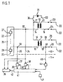
- Figure 1 shows a block diagram of a measuring device which is connected to an ignition system
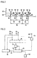
- Figure 2 shows one Time course of ignition pulses in an ignition system
- Figure 3 shows a block diagram of a measuring device.
- FIG. 1 an ignition system 10 is shown, which is connected to a measuring device 11. Ignition system 10 and measuring device 11 are drawn separated from one another by dashed lines.
- the ignition system 10 contains two ignition coils 12, 13, which each have first primary connections 14, 15, second primary connections 16, 17, first secondary connections 18, 19 and second secondary connections 20, 21.
- the secondary connections 18, 19, 20, 21 of the ignition coils 12, 13 are each connected to spark plugs 23, 24, 25, 26 connected to a ground 22.
- the first primary connections 14, 15 of the ignition coils 12, 13 are each connected to a switch 27, 28, which are arranged in an ignition switching device 29.
- the second primary connections 16, 17 of the ignition coil 12, 13 lead to an ignition switch 30, which connects the ignition system 10 to a battery 31 connected to ground 22.
- the two switches 27, 28 in the ignition switching device 29 are also each connected to ground 22.
- the points entered in the outline of the ignition switching device 29 mean that the ignition switching device 29 can contain further such switches in addition to the two switches 27, 28 shown. Likewise, the points in the connecting line of the second primary connections 16, 17 of the ignition coils 12, 13 mean that this line can lead to further ignition coils.
- the measuring lines 34, 35 are connected to an evaluation arrangement 36 and each with comparators 37, 38.
- the comparators 37, 38 each output signals 39, 40 to a signal processing arrangement 41.
- the arrangement 41 in turn outputs an output signal 42 to the evaluation arrangement 36.
- the signal processing arrangement 41 also receives input signals from a cylinder number transmitter 43 and from a reference signal transmitter 44.
- the reference signal generator 44 is connected via a further measuring line 45 and via a further contact 46 to a line which leads to the spark plug 26.
- FIG. 2 shows a signal curve as a function of the time T that occurs in the ignition system 10.
- the voltage U that occurs at the contacts 32, 33 is indicated.
- the signal curve can initially occur either at one contact 33. Furthermore, it is possible to combine the signals at the contacts 32, 33, so that the signal curve shown in FIG. 2 arises from the superimposition of two or more signals.
- the signal is referred to as the primary ignition signal.
- An ignition pulse likewise occurs on the primary side of the ignition coil, the amplitude of which reaches a value which is mainly given by the transmission ratio of the ignition coil between the primary and secondary windings.
- the four successive ignition pulses shown in FIG. 2 have the reference numerals 51, 52, 53, 54.
- the ignition phase 51, 52, 53, 54 is followed in each case by the burning phase 55, while the one on the spark plug 23, 24, 25, 26 There is a gas discharge.
- the burning phase 55 is followed by an opening phase 56 during which the switch 27, 28 is open.
- the closing phase 50 begins, a new ignition process is initiated.
- a first and a second threshold 57, 58 are entered in FIG. 2, the first threshold 57 being exceeded by the first, third and fourth ignition pulses 51, 53, 54 and the second threshold 58 being exceeded by all ignition pulses 51, 52, 53, 54.
- the time intervals between the individual ignition pulses 51, 52, 53, 54 are also entered. An interval begins where the amplitude of the ignition pulses 51, 52, 53, 54 either reaches the first threshold 57 or the second threshold 58 and ends at the corresponding point of the subsequent pulse.
- a rising edge 59 of the ignition pulses 51, 52, 53, 54 is provided as the intersection points of the ignition pulses 51, 52, 53, 54 with the thresholds 57, 58.
- a first time interval 60 lies between the first and the third ignition pulse 53, based on the first threshold 57
- second time interval 61 lies between the third and fourth ignition pulses 53, 54, likewise with respect to the first threshold 57.
- Third, fourth and fifth time intervals 62, 63, 64 each lie between two successive ignition pulses 51, 52; 52, 53; 53, 54, based in each case on the second threshold 58.
- FIG. 1 Another block diagram of the measuring device 11 is shown in FIG. Corresponding parts in Figures 1 and 3 have the same reference numerals.
- the measuring lines 34, 35 are fed to a signal combining arrangement 70, which emits an output signal to a comparator 71, the output signal 72 of which is fed to a signal processing arrangement 73.
- the methods according to the invention are explained in more detail on the basis of the block diagrams shown in FIGS. 1 and 3 in conjunction with the signal curve shown in FIG. 2:
- the ignition pulses 51, 52, 53, 54 occurring in the ignition system 10 are tapped at the contacts 32, 33. Instead of the galvanic connection of the measuring lines 34, 35 shown in FIG. 1 to the first primary connections 14, 15 of the ignition coils 12, 13, a capacitive or an inductive coupling is also possible.
- the ignition pulses 51, 52, 53, 54 can also be tapped at another point in the ignition system 10, for example on the secondary side of the ignition coils 12, 13. Instead of the primary-side ignition signal curve shown in FIG. 2, there is then, for example, a secondary-side ignition signal curve, although the characteristic ignition pulses 51, 52, 53, 54 are present.
- the measuring lines 34, 35 leading to the measuring device 11 are usually initially in a signal conditioning circuit, which is not entered in Figure 1, prepared for further signal processing.
- a signal conditioning circuit can contain a voltage divider, an impedance converter or an amplifier circuit.
- the signals are then fed to the evaluation arrangement 36, which carries out a qualitative or quantitative analysis of the signals.
- Some of these evaluations depend on the time. Such evaluations are, for example, the determination of the ignition times of the individual cylinders in chronological order during an engine cycle.
- a digital signal is used instead of the analog signal shown in FIG. 2, which starts or stops devices for determining times through a defined level or a defined edge.
- the output signal 42 of the signal processing arrangement 42 is such a signal with which the evaluation arrangement 36 carries out the time-related evaluations.
- the signal 42 contains, for example, pulses which are resolved every time an ignition pulse 51, 52, 53, 54 occurs.
- a careful determination of the threshold 57, 58 is necessary, and if the threshold pulses 57, 52, 53, 54 are exceeded, a pulse is triggered in each case.
- the threshold 57, 58 is variable. It is considered equivalent to this measure that the threshold 57, 58 is fixed and that the amplitude of the signal is changed in accordance with the arrangement of the prior art mentioned at the beginning.
- the signals on the measuring lines 34, 35 are fed to the comparators 37, 38, respectively.
- the signal processing arrangement 41 initially sets the threshold 57, 58 to a high value, which is reduced as a function of determined time intervals and / or as a function of counting results.
- the threshold 57, 58 is set to a value at which the number of detected ignition pulses 51, 52, 53, 54 is within an interval which is given by the distance between two successive pulses of the reference cylinder , matches an expected number.
- the prerequisite for this procedure is the detection of ignition pulses from a reference cylinder.
- the spark plug 26 is provided to ignite the reference cylinder.
- the measuring line 45 is therefore connected to the further contact 46 on the line leading to the spark plug 26. Instead of the galvanic connection shown, a capacitive as well as an inductive coupling is possible.
- the further measuring line 45 feeds the tapped signal to the reference signal generator 44, which emits an output signal to the signal processing arrangement 41.
- the reference signal generator contains, for example, a voltage divider, an impedance converter and / or an amplifier and a comparator.
- the reference signal generator 44 is also intended to emit a pulse-like signal, such as the comparators 37, 38, which is produced by comparing the input signal with a threshold.
- a threshold it is much easier to specify a threshold here because the input signal can be clearly identified.
- the reference signal is detected by a trigger gun that detects the spark plug current flowing in the secondary circuit or at least its changes.
- the reference signal generator 44 emits a signal to the signal processing arrangement 41 each time the first ignition pulse 51 occurs, for example. So that the arrangement 41 can determine the ignition pulses occurring within an engine cycle, the number of cylinders must be communicated to it will.
- the cylinder counter 43 is provided, which is controlled, for example, by an input.
- the variable threshold 57, 58 is determined during operation such that the signal processing arrangement 41, starting from the first ignition pulse 51, counts four ignition pulses until the first ignition pulse occurs again, which corresponds to the ignition pulse for the reference cylinders. In the example, a four-cylinder internal combustion engine has been assumed.
- a combination of the method with a further criterion as described above is particularly advantageous.
- a further increase in operational safety is thereby achieved, one method representing a plausibility check of the other method. So it is possible to use the first criterion first and to check the result with the second criterion and vice versa.
- the signal processing arrangement 73 differs from the arrangement 41 shown in FIG. 1 with regard to the specification of the threshold for the comparator 71.
- a uniform threshold is preferably provided for a threshold that changes over time, the threshold being able to be defined either for individual expected ignition pulses or groups of ignition pulses. From previous ignition pulses, the threshold can be specified in advance at a point in time after which the next ignition pulse is expected.
- the methods according to the invention can be implemented in analog circuit technology as well as run in a microprocessor system.
- the detected signals are first subjected to an analog / digital conversion and then the comparison operations and evaluation processes are carried out in the numerical range.
Landscapes
- Engineering & Computer Science (AREA)
- Chemical & Material Sciences (AREA)
- Combustion & Propulsion (AREA)
- Mechanical Engineering (AREA)
- General Engineering & Computer Science (AREA)
- Ignition Installations For Internal Combustion Engines (AREA)
Applications Claiming Priority (3)
| Application Number | Priority Date | Filing Date | Title |
|---|---|---|---|
| DE4136232A DE4136232A1 (de) | 1991-11-02 | 1991-11-02 | Verfahren zum auswerten von zuendimpulsen |
| DE4136232 | 1991-11-02 | ||
| EP92116797A EP0540878B1 (fr) | 1991-11-02 | 1992-10-01 | Dispositif pour l'évaluation d'impulsions d'allumage |
Related Parent Applications (2)
| Application Number | Title | Priority Date | Filing Date |
|---|---|---|---|
| EP92116797.9 Division | 1992-10-01 | ||
| EP92116797A Division EP0540878B1 (fr) | 1991-11-02 | 1992-10-01 | Dispositif pour l'évaluation d'impulsions d'allumage |
Publications (3)
| Publication Number | Publication Date |
|---|---|
| EP0732499A2 true EP0732499A2 (fr) | 1996-09-18 |
| EP0732499A3 EP0732499A3 (fr) | 1997-10-29 |
| EP0732499B1 EP0732499B1 (fr) | 2000-07-26 |
Family
ID=6444029
Family Applications (2)
| Application Number | Title | Priority Date | Filing Date |
|---|---|---|---|
| EP96109664A Expired - Lifetime EP0732499B1 (fr) | 1991-11-02 | 1992-10-01 | Dispositif pour l'évaluation d'impulsions d'allumage |
| EP92116797A Expired - Lifetime EP0540878B1 (fr) | 1991-11-02 | 1992-10-01 | Dispositif pour l'évaluation d'impulsions d'allumage |
Family Applications After (1)
| Application Number | Title | Priority Date | Filing Date |
|---|---|---|---|
| EP92116797A Expired - Lifetime EP0540878B1 (fr) | 1991-11-02 | 1992-10-01 | Dispositif pour l'évaluation d'impulsions d'allumage |
Country Status (3)
| Country | Link |
|---|---|
| EP (2) | EP0732499B1 (fr) |
| DE (3) | DE4136232A1 (fr) |
| ES (2) | ES2150619T3 (fr) |
Families Citing this family (2)
| Publication number | Priority date | Publication date | Assignee | Title |
|---|---|---|---|---|
| DE3925221A1 (de) * | 1989-07-29 | 1991-01-31 | Vdo Schindling | Verfahren und schaltungsanordnung zur ueberwachung von funkenstrecken |
| DE4223713A1 (de) * | 1992-07-18 | 1994-01-20 | Bosch Gmbh Robert | Vorrichtung zum Erfassen eines Signales |
Family Cites Families (13)
| Publication number | Priority date | Publication date | Assignee | Title |
|---|---|---|---|---|
| DE2234957A1 (de) * | 1972-07-15 | 1974-01-31 | Bosch Gmbh Robert | Schaltungsanordnung zur gewinnung von elektrischen triggersignalen |
| DE2343895A1 (de) * | 1973-08-31 | 1975-03-13 | Bosch Gmbh Robert | Verfahren und einrichtung zur ueberpruefung der zuendanlage von brennkraftmaschinen |
| DE2431799B2 (de) * | 1974-07-02 | 1977-06-02 | Gebr. Hofmann Kg Maschinenfabrik, 6100 Darmstadt | Schaltung zur aufbereitung impulsfoermiger messignale eines induktiven gebers, der den zuendstrom in einer zuendanlage eines ottomotors abgreift |
| JPS5810580B2 (ja) * | 1979-05-14 | 1983-02-26 | 自動車機器技術研究組合 | 自動車の点火装置の診断装置 |
| DE3400786A1 (de) * | 1984-01-12 | 1985-07-18 | Robert Bosch Gmbh, 7000 Stuttgart | Zuendungsmessgeraet |
| DE3505440A1 (de) * | 1985-02-16 | 1986-08-21 | Hermann, Horst, 8501 Oberasbach | Verfahren zur laufzustandsanalyse an verbrennungsmotoren mit elektrischer zuendanlage sowie vorrichtung zur durchfuehrung des verfahrens |
| IT1206836B (it) * | 1987-01-09 | 1989-05-11 | Fiat Auto Spa | Procedimento e dispositivo per il rilievo e la segnalazione di anomalie di funzionamento dell impianto di accensione di motori a combustione interna particolarmente per autoveicoli provvisti di marmitta catalitica |
| US4788505A (en) * | 1987-09-11 | 1988-11-29 | Pacific Northwest Electronics | Advance reference cylinder trigger generator |
| US4847562A (en) * | 1987-09-11 | 1989-07-11 | Pacific Northwest Electronics | Ignition coil primary winding signal processing system |
| DE3735234C2 (de) * | 1987-10-17 | 1995-05-11 | Opel Adam Ag | Zündüberwachungseinrichtung zur Erkennung von Zündaussetzern in einer Zündanlage für einen Verbrennungsmotor für ein Kraftfahrzeug |
| DE4010839A1 (de) * | 1990-04-04 | 1991-10-10 | Bosch Gmbh Robert | Vorrichtung zur erzeugung eines triggersignals aus zuendimpulsen einer zuendanlage |
| DE4011521A1 (de) * | 1990-04-10 | 1991-10-17 | Bosch Gmbh Robert | Schaltung und verfahren zum ueberwachen der funktion einer kraftfahrzeug-zuendanlage |
| US5132625A (en) * | 1990-10-01 | 1992-07-21 | Actron Manufacturing Company | Distributorless ignition adapter for diagnostic oscilloscopes |
-
1991
- 1991-11-02 DE DE4136232A patent/DE4136232A1/de not_active Ceased
-
1992
- 1992-10-01 ES ES96109664T patent/ES2150619T3/es not_active Expired - Lifetime
- 1992-10-01 DE DE59209853T patent/DE59209853D1/de not_active Expired - Lifetime
- 1992-10-01 ES ES92116797T patent/ES2128334T3/es not_active Expired - Lifetime
- 1992-10-01 DE DE59209617T patent/DE59209617D1/de not_active Expired - Lifetime
- 1992-10-01 EP EP96109664A patent/EP0732499B1/fr not_active Expired - Lifetime
- 1992-10-01 EP EP92116797A patent/EP0540878B1/fr not_active Expired - Lifetime
Also Published As
| Publication number | Publication date |
|---|---|
| EP0540878A3 (en) | 1994-08-10 |
| DE59209853D1 (de) | 2000-08-31 |
| DE59209617D1 (de) | 1999-02-25 |
| EP0732499B1 (fr) | 2000-07-26 |
| EP0540878B1 (fr) | 1999-01-13 |
| ES2128334T3 (es) | 1999-05-16 |
| ES2150619T3 (es) | 2000-12-01 |
| DE4136232A1 (de) | 1993-05-06 |
| EP0540878A2 (fr) | 1993-05-12 |
| EP0732499A3 (fr) | 1997-10-29 |
Similar Documents
| Publication | Publication Date | Title |
|---|---|---|
| DE3785439T2 (de) | Verfahren und geraet zur feststellung und anzeige von zuendungsanomalien beim betrieb von zuendsystemen von verbrennungsmaschinen, insbesondere fuer mit einem katalysator ausgestattete motorfahrzeuge. | |
| DE4207140C2 (de) | Fehlzündungsdetektorsystem zum Detektieren einer Fehlzündung in einem Verbrennungsmotor | |
| DE19601353C2 (de) | Verbrennungszustandserfassungsvorrichtung für eine Brennkraftmaschine mit innerer Verbrennung | |
| DE1928679C3 (de) | Elektrische Schaltungsanordnung zur Prüfung der Zündanlage von Brennkraftmaschinen | |
| DE3128554C2 (fr) | ||
| DE69720853T2 (de) | Verfahren zur Ermittlung von vorzeitigen Zündungen | |
| DE19514633A1 (de) | Vorrichtung zur Erfassung von Fehlzündungen in einer Brennkraftmaschine | |
| DE4204484A1 (de) | Verbrennungsdetektorvorrichtung fuer eine brennkraftmaschine | |
| EP0470277B1 (fr) | Installation d'allumage pour moteurs à combustion | |
| DE19524499B4 (de) | Zündanlage für eine Brennkraftmaschine | |
| DE60119879T2 (de) | Vorrichtung zur Erkennung von Zündaussetzern bei einer Brennkraftmaschine | |
| EP0455649B1 (fr) | Procede d'attribution de signaux d'allumage a un cylindre de reference | |
| DE3706786C1 (en) | Device for monitoring at least two electrical loads in motor vehicles | |
| DE2040913A1 (de) | Einrichtung zur automatischen Erfassung des zeitlichen Verlaufs der Zuendspannungen in einer Mehrzylinder-Brennkraftmaschine | |
| EP0732499B1 (fr) | Dispositif pour l'évaluation d'impulsions d'allumage | |
| DE3417676C2 (fr) | ||
| DE69116430T2 (de) | Zündanlage für innere Brennkraftmaschinen, insbesondere zur Detektion von Zündfunken-Aussetzern | |
| DE3128027A1 (de) | "vorrichtung zum erkennen des klopfens bei brennkraftmaschinen" | |
| EP0502549B1 (fr) | Dispositif de surveillance de l'étincelle dans une installation d'allumage | |
| DE2431799B2 (de) | Schaltung zur aufbereitung impulsfoermiger messignale eines induktiven gebers, der den zuendstrom in einer zuendanlage eines ottomotors abgreift | |
| EP0705386B1 (fr) | Procede permettant de detecter un groupe d'impulsions d'allumage | |
| EP0707144B1 (fr) | Dispositif de détection des signaux d'allumage | |
| EP0529281B1 (fr) | Procédé de détection d'une mise en contact des lignes de mesure | |
| DE3400786C2 (fr) | ||
| EP1054154B1 (fr) | Dispositif pour la mesure d'un courant d'ions pour moteur à combustion interne |
Legal Events
| Date | Code | Title | Description |
|---|---|---|---|
| PUAI | Public reference made under article 153(3) epc to a published international application that has entered the european phase |
Free format text: ORIGINAL CODE: 0009012 |
|
| AC | Divisional application: reference to earlier application |
Ref document number: 540878 Country of ref document: EP |
|
| AK | Designated contracting states |
Kind code of ref document: A2 Designated state(s): CH DE ES FR GB IT LI SE |
|
| PUAL | Search report despatched |
Free format text: ORIGINAL CODE: 0009013 |
|
| AK | Designated contracting states |
Kind code of ref document: A3 Designated state(s): CH DE ES FR GB IT LI SE |
|
| 17P | Request for examination filed |
Effective date: 19980429 |
|
| 17Q | First examination report despatched |
Effective date: 19990104 |
|
| GRAG | Despatch of communication of intention to grant |
Free format text: ORIGINAL CODE: EPIDOS AGRA |
|
| GRAG | Despatch of communication of intention to grant |
Free format text: ORIGINAL CODE: EPIDOS AGRA |
|
| GRAH | Despatch of communication of intention to grant a patent |
Free format text: ORIGINAL CODE: EPIDOS IGRA |
|
| GRAH | Despatch of communication of intention to grant a patent |
Free format text: ORIGINAL CODE: EPIDOS IGRA |
|
| GRAA | (expected) grant |
Free format text: ORIGINAL CODE: 0009210 |
|
| AC | Divisional application: reference to earlier application |
Ref document number: 540878 Country of ref document: EP |
|
| AK | Designated contracting states |
Kind code of ref document: B1 Designated state(s): CH DE ES FR GB IT LI SE |
|
| REG | Reference to a national code |
Ref country code: CH Ref legal event code: NV Representative=s name: SCINTILLA AG, DIREKTION Ref country code: CH Ref legal event code: EP |
|
| REF | Corresponds to: |
Ref document number: 59209853 Country of ref document: DE Date of ref document: 20000831 |
|
| ITF | It: translation for a ep patent filed | ||
| GBT | Gb: translation of ep patent filed (gb section 77(6)(a)/1977) |
Effective date: 20001004 |
|
| ET | Fr: translation filed | ||
| REG | Reference to a national code |
Ref country code: ES Ref legal event code: FG2A Ref document number: 2150619 Country of ref document: ES Kind code of ref document: T3 |
|
| PLBE | No opposition filed within time limit |
Free format text: ORIGINAL CODE: 0009261 |
|
| STAA | Information on the status of an ep patent application or granted ep patent |
Free format text: STATUS: NO OPPOSITION FILED WITHIN TIME LIMIT |
|
| 26N | No opposition filed | ||
| REG | Reference to a national code |
Ref country code: GB Ref legal event code: IF02 |
|
| PGFP | Annual fee paid to national office [announced via postgrant information from national office to epo] |
Ref country code: FR Payment date: 20041019 Year of fee payment: 13 |
|
| PGFP | Annual fee paid to national office [announced via postgrant information from national office to epo] |
Ref country code: SE Payment date: 20041025 Year of fee payment: 13 Ref country code: CH Payment date: 20041025 Year of fee payment: 13 |
|
| PGFP | Annual fee paid to national office [announced via postgrant information from national office to epo] |
Ref country code: ES Payment date: 20041026 Year of fee payment: 13 |
|
| PG25 | Lapsed in a contracting state [announced via postgrant information from national office to epo] |
Ref country code: SE Free format text: LAPSE BECAUSE OF NON-PAYMENT OF DUE FEES Effective date: 20051002 |
|
| PG25 | Lapsed in a contracting state [announced via postgrant information from national office to epo] |
Ref country code: ES Free format text: LAPSE BECAUSE OF NON-PAYMENT OF DUE FEES Effective date: 20051003 |
|
| PG25 | Lapsed in a contracting state [announced via postgrant information from national office to epo] |
Ref country code: LI Free format text: LAPSE BECAUSE OF NON-PAYMENT OF DUE FEES Effective date: 20051031 Ref country code: CH Free format text: LAPSE BECAUSE OF NON-PAYMENT OF DUE FEES Effective date: 20051031 |
|
| REG | Reference to a national code |
Ref country code: CH Ref legal event code: PL |
|
| EUG | Se: european patent has lapsed | ||
| PG25 | Lapsed in a contracting state [announced via postgrant information from national office to epo] |
Ref country code: FR Free format text: LAPSE BECAUSE OF NON-PAYMENT OF DUE FEES Effective date: 20060630 |
|
| REG | Reference to a national code |
Ref country code: FR Ref legal event code: ST Effective date: 20060630 |
|
| REG | Reference to a national code |
Ref country code: ES Ref legal event code: FD2A Effective date: 20051003 |
|
| PGFP | Annual fee paid to national office [announced via postgrant information from national office to epo] |
Ref country code: DE Payment date: 20091215 Year of fee payment: 18 |
|
| PGFP | Annual fee paid to national office [announced via postgrant information from national office to epo] |
Ref country code: IT Payment date: 20101023 Year of fee payment: 19 Ref country code: GB Payment date: 20101021 Year of fee payment: 19 |
|
| REG | Reference to a national code |
Ref country code: DE Ref legal event code: R119 Ref document number: 59209853 Country of ref document: DE Effective date: 20110502 |
|
| GBPC | Gb: european patent ceased through non-payment of renewal fee |
Effective date: 20111001 |
|
| PG25 | Lapsed in a contracting state [announced via postgrant information from national office to epo] |
Ref country code: IT Free format text: LAPSE BECAUSE OF NON-PAYMENT OF DUE FEES Effective date: 20111001 Ref country code: GB Free format text: LAPSE BECAUSE OF NON-PAYMENT OF DUE FEES Effective date: 20111001 |
|
| PG25 | Lapsed in a contracting state [announced via postgrant information from national office to epo] |
Ref country code: DE Free format text: LAPSE BECAUSE OF NON-PAYMENT OF DUE FEES Effective date: 20110502 |