EP0732503A1 - Spiralverdichter - Google Patents
Spiralverdichter Download PDFInfo
- Publication number
- EP0732503A1 EP0732503A1 EP96103961A EP96103961A EP0732503A1 EP 0732503 A1 EP0732503 A1 EP 0732503A1 EP 96103961 A EP96103961 A EP 96103961A EP 96103961 A EP96103961 A EP 96103961A EP 0732503 A1 EP0732503 A1 EP 0732503A1
- Authority
- EP
- European Patent Office
- Prior art keywords
- elastic body
- type compressor
- bush
- scroll member
- drive
- Prior art date
- Legal status (The legal status is an assumption and is not a legal conclusion. Google has not performed a legal analysis and makes no representation as to the accuracy of the status listed.)
- Granted
Links
- 230000007246 mechanism Effects 0.000 claims abstract description 36
- 238000007906 compression Methods 0.000 claims description 62
- 230000006835 compression Effects 0.000 claims description 55
- 239000000314 lubricant Substances 0.000 claims description 34
- 239000012530 fluid Substances 0.000 claims description 32
- 230000035939 shock Effects 0.000 description 11
- 238000009434 installation Methods 0.000 description 8
- 230000000694 effects Effects 0.000 description 5
- 230000036961 partial effect Effects 0.000 description 5
- 239000003507 refrigerant Substances 0.000 description 5
- 238000007789 sealing Methods 0.000 description 5
- 238000005299 abrasion Methods 0.000 description 4
- 230000002829 reductive effect Effects 0.000 description 4
- 239000000463 material Substances 0.000 description 3
- 230000000644 propagated effect Effects 0.000 description 3
- 230000008901 benefit Effects 0.000 description 2
- 230000008034 disappearance Effects 0.000 description 2
- 238000005461 lubrication Methods 0.000 description 2
- 230000014759 maintenance of location Effects 0.000 description 2
- 239000002184 metal Substances 0.000 description 2
- 238000000034 method Methods 0.000 description 2
- 230000002159 abnormal effect Effects 0.000 description 1
- 230000004913 activation Effects 0.000 description 1
- 238000004378 air conditioning Methods 0.000 description 1
- 230000015572 biosynthetic process Effects 0.000 description 1
- 230000000903 blocking effect Effects 0.000 description 1
- 230000008859 change Effects 0.000 description 1
- 238000002485 combustion reaction Methods 0.000 description 1
- 230000008094 contradictory effect Effects 0.000 description 1
- 230000003247 decreasing effect Effects 0.000 description 1
- 230000002708 enhancing effect Effects 0.000 description 1
- 230000006872 improvement Effects 0.000 description 1
- 239000000203 mixture Substances 0.000 description 1
- 238000007747 plating Methods 0.000 description 1
- 230000002265 prevention Effects 0.000 description 1
- 230000009467 reduction Effects 0.000 description 1
- 230000002441 reversible effect Effects 0.000 description 1
- 125000006850 spacer group Chemical group 0.000 description 1
Images




Classifications
-
- F—MECHANICAL ENGINEERING; LIGHTING; HEATING; WEAPONS; BLASTING
- F04—POSITIVE - DISPLACEMENT MACHINES FOR LIQUIDS; PUMPS FOR LIQUIDS OR ELASTIC FLUIDS
- F04C—ROTARY-PISTON, OR OSCILLATING-PISTON, POSITIVE-DISPLACEMENT MACHINES FOR LIQUIDS; ROTARY-PISTON, OR OSCILLATING-PISTON, POSITIVE-DISPLACEMENT PUMPS
- F04C29/00—Component parts, details or accessories of pumps or pumping installations, not provided for in groups F04C18/00 - F04C28/00
- F04C29/0042—Driving elements, brakes, couplings, transmissions specially adapted for pumps
- F04C29/005—Means for transmitting movement from the prime mover to driven parts of the pump, e.g. clutches, couplings, transmissions
- F04C29/0057—Means for transmitting movement from the prime mover to driven parts of the pump, e.g. clutches, couplings, transmissions for eccentric movement
Definitions
- the present invention relates to a scroll type compressor which is preferable when used as a refrigerant compressor in an air conditioning apparatus for an automobile for example and particularly relates to a scroll type compressor provided with a driven crank mechanism which is improved for preventing noise generated when an actual operation for actually compressing a fluid (refrigerant) is started up or shut down (also referred to as ON/OFF time).
- a scroll type compressor In a scroll type compressor, generally a fixed scroll member fixed and supported in a housing and having a spiral-shaped vane and a movable scroll member having a similar spiral-shaped vane for engaging with this are engaged with each other while shifted in phase in the direction of rotation on an eccentric axis so as to form a plurality of fluid compression pockets having crescent shapes when seen in an axial direction between the two spiral-shaped vanes.
- the movable scroll member is driven by rotation of a drive shaft via a crank mechanism and thereby performs an orbiting movement substantially not accompanied by rotation.
- the fluid compression pockets move from the outer periphery of the scroll member toward the center portion.
- the volume of the fluid compression pockets is reduced during this time. Therefore, the fluid fetched into the fluid compression pockets at the outer periphery is compressed and exhausted from the center portion.
- These driven crank mechanisms have slider portions, one of which is able to slidably move in a radial direction with respect to the other between the drive shaft side and the movable scroll member side driven by this, whereby the magnitude of the eccentricity of the movable scroll member with respect to the center of the fixed scroll member and the eccentricity of the drive shaft are changed and the state of contact in the contact portion forming a sealed portion of the fluid compression pocket between the spiral-shaped vanes of the fixed scroll member and the movable scroll member changes along with the change of the amount of eccentricity.
- one method for reducing the startup shock of a scroll type compressor is to use one and another member provided inside a driven crank mechanism connecting the drive shaft and the movable scroll member, for example a drive key in the substantially radial direction which is formed integrally with the drive shaft and a groove in the substantially radial direction formed in a bush supporting a cylindrical boss portion of the movable scroll member via a bearing, so as to constitute a slider portion and also to use a single elastic member to bias the slider portion such as providing a spring between one end surface of the drive key in the radial direction and the end surface of the groove of the bush corresponding to that end surface and use the biasing force of the same to form a gap at the contact portion between the vane of the fixed scroll member and the vane of the movable scroll member at the time of shutting down or starting up the operation of the compressor.
- a scroll type compressor having a driven crank mechanism has a variable amount of eccentricity of the movable scroll member, so when preventing startup shock by forming a gap at the contact portion between the spiral-shaped vanes at the time when the compressor is shut down, when the operation is restarted next, the anti-compression force of the fluid in the fluid compression pockets increases the amount of eccentricity of the movable scroll member and pushes the vane of the movable scroll member against the vane of the fixed scroll member, so that the gap between them is closed, but at this time, noise is generated since the spiral-shaped vane of the movable scroll member strikes the spiral-shaped vane of the fixed scroll member Moreover, there exists a case where the drive key constituting part of the slider portion will strike the terminal end of the groove of the bush inside the driven crank mechanism and cause noise.
- an object of the present invention is to provide an effective means having a simple configuration which can prevent the generation of noise at the contact portion between the spiral-shaped vanes in both of the cases of startup and shutdown of the scroll type compressor.
- the present invention provides a scroll type compressor as disclosed in the claims.
- the scroll type compressor of the present invention performs the same fundamental operation as that of a conventional scroll type compressor, that is, fetches a fluid by fluid compression pockets formed between a spiral-shaped vane of a fixed scroll member and a spiral-shaped vane of a movable scroll member and compresses the fluid by continuous reduction of the volume of the fluid compression pockets.
- a characteristic feature of the scroll type compressor of the present invention resides in the point of provision of at least one elastic member forming two compression regions between a drive projection and a groove so as to buffer collisions occurring between the two ends of the drive projection constituting part of a slider portion of a driven crank mechanism in the radial direction and the inner surfaces of the two ends of said groove facing the same, collisions between the spiral-shaped vanes of two scroll members, and collisions between the spiral-shaped vanes of the two scroll members which occur at the time of the startup of the scroll type compressor and thereby the prevention of the generation of noise due to the same.
- the drive projection or groove constituting part of the slider portion of the driven crank mechanism slides along the flat surface of the opposing groove or projection by the partial force of the increasing anti-compression force or the like and the terminal ends of the projection and groove collide or the spiral-shaped vane of the movable scroll member collides with the spiral-shaped vane of the fixed scroll member before or after this, thereby forming a sealing portion of the fluid compression pockets, but before this collision and the generation of noise due to this occur, one of the two compression regions caused by the elastic body attached between the drive projection and the groove is compressed, the collision is buffered by the repulsion force of the elastic body, and the occurrence of collisions and noise is prevented.
- the drive projection or groove in the driven crank mechanism slides along the flat surface of the opposing groove or projection due to the disappearance of the anti-compression force, the terminal ends of the projection and groove of the opposing side collide, or the spiral-shaped vane of the movable scroll member collides with the spiral-shaped vane of the fixed scroll member due to rotation, and noise is generated by the same, but in this case, the compression region opposite to that used at the time of the startup among the two compression regions created by the elastic body is compressed preceding the collision, so the shock is buffered by the repulsion force of the compression region of the elastic body and the occurrence of the collision and noise is prevented.
- noise due to the collision of the sliding portion of the driven crank mechanism and the collision of the spiral-shaped vanes of the scroll members which are apt to occur at the time of the startup of the scroll type compressor can be prevented.
- the invention is not restricted to this. It is also possible to prevent noise due to collision at a portion opposite to that at the time of the activation of the sliding portion of the driven crank mechanism which is apt to occur at the time of the shut down of the actual operation. Accordingly, by addition of these effects with each other, it becomes possible to remarkably reduce the noise of the scroll type compressor.
- FIG. 1 shows the overall configuration of a scroll type compressor 1 according to an embodiment of the present invention.
- the configuration of the partial lateral cross-section is shown in Fig. 2.
- This scroll type compressor 1 has a similar configuration to that of the conventional one in most parts.
- a housing 2 comprises three parts integrally fastened with each other by means such as bolts, that is, a center housing 2a, a front housing 2b, and a rear housing 2c.
- a fixed scroll member 3 is formed in an internal portion of the center housing 2 integrally with this, and a drive shaft 5 supported by a bearing 4 is extended in the front housing 2b so as to penetrate through this.
- the drive shaft 5 rotatably supported by the bearing 4 introduces a rotation force propagated from a prime mover such as a not illustrated internal combustion engine (a hydraulic motor or electric motor is also possible) into the scroll type compressor 1.
- a prime mover such as a not illustrated internal combustion engine (a hydraulic motor or electric motor is also possible) into the scroll type compressor 1.
- the driven crank mechanism 6 On the axial end of an enlarged diameter portion 5a of the drive shaft, the driven crank mechanism 6 provided with the characteristic of the present invention is formed. The configuration thereof will be explained in detail later.
- a movable scroll member 7 is connected to the driven crank mechanism 6.
- On back of the movable scroll member 7, there are provided a thrust supporting and rotation preventing mechanism 8 which allows only the orbiting of the movable scroll member 7 and prevents the rotation of the movable scroll member 7 at the driving and, at the same time, supports the thrust in the axial direction acting upon the movable scroll member.
- the fixed scroll member 3 and the movable scroll member 7 are provided with spiral-shaped vanes 3a and 7a having substantially the same shape and have the same length (width) in the axial direction. They supported in combination in a manner so that they are engaged with each other shifted in phase by 180 degrees in the rotation direction relative to each other and in an eccentric state, whereby two or more fluid compression pockets P of crescent shapes when viewed in the axial direction are formed between those vanes for compressing the fluid.
- the movable scroll member 7 comprises a spiral-shaped vane 7a and a disk-like side plate 7b which is integrally attached to the same.
- a boss portion 7c having a large diameter and a hollow cylindrical shape and projecting leftward in the axial direction is formed as an integral body at the center of the back of the side plate 7b.
- the boss portion 7c is rotatably connected via a needle bearing 9 and a driven crank mechanism 6, a detailed configuration of which is shown in Fig. 3 to Fig. 6, to the drive shaft 5 and is supported by this.
- the driven crank mechanism 6 mainly comprise a drive key 10 which is integrally formed so as to project from the eccentric position on one end surface of the diameter enlarged portion 5a of the drive shaft 5 in the axial direction; a short column-shaped bush 11 which supports the boss portion 7c of the movable scroll member 7 so that it can rotate; and an elastic body 12 such as an annular rubber inserted between the drive key 10 and the bush 11 as the characteristic feature of the present invention.
- a balance weight 13 for canceling at least a part of the centrifugal force acting upon the movable scroll member 7 orbiting eccentric with respect to the drive shaft 5 is integrally attached to the bush 11.
- 15 shown in Fig. 3 etc. is a snap ring for stopping the detachment of the bush 11 and fitted with a groove 10d formed in the end portion of the drive key 10.
- Reference numeral 15a is a washer used for auxiliary use.
- a thrust supporting and rotation preventing mechanism 8 in the embodiment shown in Fig. 1 comprises: a plurality of rotation hindering pins 8a attached to an inner surface of the front housing 2b in the axial direction; a plurality of rotation hindering pins 8b attached to the back surface of the side plate 7b of the movable scroll member 7 in the axial direction so as to be engaged with this; a ring 8c having a circular hole into which a pair of rotation hindering pins 8a and 8b are loosely inserted; schematically an annular smooth plate 14 excellent in the abrasion resistance inserted as a spacer to between the inner surface of the front housing 2b and the back surface of the side plate 7b of the movable scroll member 7, etc. It is also possible even if a hard metal plating is applied to the back surface of the side plate 7b of the movable scroll member which comes into sliding contact with the front surface of the
- an exhaust port 3c is opened at the center of the side plate 3b of the fixed scroll member 3 and an exhaust valve 16 made of a thin metal piece having resiliency is attached to the side plate 3b in a cantilever manner so as to close the exhaust port 3c from the outside.
- Reference numeral 17 is a valve stopper preventing excessive opening of the exhaust valve 16.
- 18 is a shaft sealing device which seals the drive shaft 5 and the shaft opening port of the front housing 2b
- 19 is an O-ring sealing the front housing 2b and the center housing 2a
- 20 is a bolt fastening the center housing 2a and the rear housing 2c.
- a space 2e in the rear housing 2c acts as a high pressure chamber into which the compressed fluid is exhausted, that is, an exhaust chamber.
- the drive key 10 formed at the shaft end of the drive shaft 5 is also referred to as a two-surface width portion.
- two planes 10a and 10b parallel to the radial direction are formed.
- the drive key 10 is engaged with the bush 11 so that it can slide with respect to the groove 11a formed in the radial direction or in parallel to the radial direction.
- the length of the groove 11a in the radial direction or the direction parallel to the radial direction becomes longer than that of the drive key 10 by exactly a predetermined value.
- the inner surface of the annular elastic body 12 corresponding to the characteristic feature of the present invention, is fitted over the outside of the columnar portion 10c of the base portion of the drive key 10.
- the outer surface of the elastic body 12 is in contact with the inner surface of the annular step portion 11b formed at the base portion of the groove 11a of the bush 11 (part on left side in Fig. 1 and Fig. 3). Due to this, the bush 11 having the groove 11a can move relatively in the radial direction with respect to the drive key 10 by deformation of at least one part of the annular elastic body 12 under compression.
- the elastic body 12 generates a centripetal force preventing relative sliding between the drive key 10 and the bush 11.
- the scroll type compressor 1 of the illustrated embodiment is constituted in this way, when the drive shaft 5 is driven to rotate by an outside prime mover, as a basic operation of the scroll type compressor, similar to that of the conventional compressor, the bush 11 constituting a part of the driven crank mechanism 6 is rotated while being eccentric with respect to the drive shaft 5, therefore also the movable scroll member 7 engaged via the needle bearing 9 in the boss portion 7c intends to rotate similarly, but since the thrust supporting and rotation preventing mechanism 8 is provided, the rotation of the movable scroll member 7 is hindered and it will only engage in orbital motion with the amount of eccentricity at that time as the radius.
- a crescent fluid compression pocket P formed between the spiral-shaped vane 3a of the fixed scroll member 3 and the spiral-shaped vane 7a of the movable scroll member 7 takes in the fluid such as the refrigerant while opening in the intake space 2f at the outer circumferences of the scroll members 3 and 7, the fluid compression pocket P is closed along with the orbital motion of the movable scroll member 7, and its volume is reduced during a period where the fluid compression pocket P gradually moves toward the center. Accordingly, the fluid in the fluid compression pocket P is compressed.
- the fluid compression pocket P becomes open at the center of the fixed scroll member 3, the refrigerant is exhausted into a space 2e, that is, the exhaust chamber, by pushing and opening the exhaust valve 16 from the exhaust port 3c.
- an elastic body 12 such as annular rubber is interposed between the drive key 10 of the driven crank mechanism 6 and the bush 11, therefore when the scroll type compressor 1 stops, there will no longer be a portion which is strongly compressed while being partially eccentric at the periphery of the elastic body 12, in other words, a partial compression stress acting upon the elastic body 12 will be balanced at the periphery of the drive key 10. Due to this, the bush 11 centripetally slides toward the center of the drive key 10 in the radial direction up to the balanced position. As a result, the fixed scroll member 7 comes to have a predetermined initial eccentricity with respect to the drive shaft 5.
- the anti-compression force due to the compression of the fluid in the fluid compression pocket P acts upon a space between the plane 10a or 10b of the drive key 10 and the plane of the groove 11a of the bush 11 in sliding contact with this, thereby to generate a force in the radial direction that increases the amount of eccentricity of the bush 11 and the movable scroll member 7 as the partial force thereof.
- This force increases the amount of eccentricity of the bush 11 together with the remaining centrifugal force not canceled by the balance weight 13 in the centrifugal force acting upon the movable scroll member 7 and generates a force pushing the movable scroll member 7 against the fixed scroll member 3 and closes the sealed portion of the fluid compression pocket P in the contact portion of the two spiral-shaped vanes 3a and 7a.
- the annular elastic body 12 is interposed between the drive key 10 and the bush 11, and therefore when the vanes contact, first a part of the elastic body 12 will be compressed in the radial direction between the column-like portion 10c of the base portion of the drive key 10 and the annular step portion 11b of the bush 11, whereby the shock of contact is buffered and the generation of noise is prevented.
- the part of the annular elastic body 12 compressed at this time will be referred to as a compression region 12a.
- the function of preventing noise is produced not only at the time of the startup of the scroll type compressor 1, but also at the shutdown. Namely, due to the disappearance of the anti-compression force in the fluid compression pocket P at the time of shutdown, the bush 11 moves in the radial direction with respect to the drive key 10 so as to reduce the amount of eccentricity of the bush 11 and the movable scroll member 7 with respect to the drive shaft 5.
- the spiral-shaped vane 7a again strikes the spiral-shaped vane 3a of the fixed scroll member 3, and this also becomes a cause of generation of noise, but in the illustrated embodiment, in the annular elastic body 12, a part on the opposite side to that of the case of startup is compressed in the radial direction between the column-like portion 10c of the base portion of the drive key 10 and the annular step portion 11b of the bush 11, whereby the shock is buffered and therefore the generation of noise is prevented also in this case.
- the part of the annular elastic body 12 compressed at this time will be referred to as a compression region 12b.
- annular elastic body 12 in the illustrated embodiment two parts located at opposite positions in the radial direction at the time of the startup and at the time of the shutdown of the scroll type compressor 1, that is, the compression regions 12a and 12b, are compressed between the column-like portion 10c of the base portion of the drive key 10 and the annular step portion 11b of the bush 11 and serve to buffer shock due to the collision between the front and rear end portions of the drive key 10 and the end portions of the inner surface of the groove 11a of the bush 11 facing the same or collision between the spiral-shaped vanes 3a and 7a of the two scroll members 3 and 7 and the other parts other than the two compression regions 12a and 12b serve to connect these two compression regions to form one series of elastic bodies 12.
- the two compression regions 12a and 12b by two independent elastic bodies not connected to each other.
- the two compression regions are constituted by two elastic bodies independent from each other, even if these elastic bodies are not provided at a position of the elastic body 12 of the illustrated embodiment, it is also possible to attach the same to the two end portions in the radial direction of the drive key 10 in for example the groove 11a of the bush 11.
- integral formation of the two compression regions by a single elastic body is more advantageous than configuring them by two mutually independent elastic bodies in various points, for example, the number of parts can be decreased by this, the assembly and installation become easy, also the retention of the position of the elastic body after assembly and installation becomes reliable, etc. Therefore, an explanation will be made of a preferred embodiment of the shape of the elastic body where the two compression regions 12a and 12b are constituted by a single elastic body by using Fig. 4 to Fig. 6.
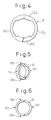
- the annular elastic body 12' shown in Fig. 4 is obtained in place of the elastic body 12 in the embodiment mentioned before, and the whole is made of a material having resiliency such as rubber and has a shape that projects inwardly in the portion of the two compression regions 12'a and 12'b. Accordingly, although the cross-sectional shape is not uniform at the circumference, there is an advantage that the two compression regions 12'a and 12'b of the elastic body and a connecting portion 12'c other than them can be given cross-sectional shapes suited to different purposes. Since the two compression regions 12'a and 12'b are connected by two connecting portions 12'c and constitute an integral annular body, they provide also the advantage of the single elastic body as mentioned before.
- Figure 5 and Fig. 6 show only the annular elastic body 12 in the embodiment shown in Fig. 3 etc.
- Figure 5 is a perspective view of the elastic body 12, and Fig. 6 is similarly a front view.
- the annular elastic body 12 is differentiated into the portions serving as the two compression regions 12a and 12b and the portion serving as the connecting portion 12c connecting them by the position in the rotation direction where it is installed, but is not differentiated into these regions before assembly and installation since it is an annular body having a uniform cross-sectional shape.
- the elastic body 12 can be produced easily and at a low cost as a simple annular body made of a material such as rubber and having a constant cross-sectional shape in the circumferential direction. Moreover, also at the assembly and installation, it is not necessary to perform the positioning in the rotation direction, and therefore the assembly and installation become further easier than the case of the elastic body 12' shown in Fig. 4.
- the elastic body 12 exhibits also an effect of retention of position in the axial direction after the assembly and installation, but there is a possibility that the position will shift in the rotation direction. However, there is no problem due to this, and therefore it may be rather more advantageous in that local fatigue of the material does not occur. Note, it is not as good as the elastic body 12' in the point of setting the cross-sectional shape to the best state for the two compression regions 12a and 12b and the connecting portion 12c.
- the cross-sectional shape of the elastic body which can be used as a general elastic body 21 that is, the integral elastic bodies 12 and 12' or two mutually independent elastic bodies constituting the two compression regions 12a and 12b, for example, as shown in Fig. 7, a shape which is a rectangle in which the length X in the axial direction has a larger dimension than the thickness Y of the radial direction (compression direction) and in addition which has roundish corners at the four corners can be mentioned.
- Figure 8 shows another preferred example of the cross-sectional shape for a general elastic body 21' as well.
- the effect produced by the vertical and lateral dimensional proportions is substantially the same as in the example shown in Fig. 7.
- the two end surfaces in the axial direction are given roundish corners, therefore the assembly and installation of the elastic body 21' become further easier than that in the example of Fig. 7.
- Figure 9 shows a preferred cross-sectional shape for still another general elastic body 21''.
- a projection 21''a is formed on one surface in the radial direction of the elastic body 21''.
- the useful function of the projection 21''a is that the abutting posture of the projection 21''a against the plane of the opposite side against which it abuts, that is, the plane of for example the column-like portion 10c of the base portion of the drive key 10 or the annular step portion 11b of the bush 11 explained in relation to the illustrated embodiment, becomes uniform and variations of the repulsion force characteristics of individual scroll type compressors 1 can be suppressed.
- lubricant oil such as the refrigerator oil can no longer flow along the surface thereof, and therefore there is a possibility that the lubrication of the sliding parts of the driven crank mechanism 6 etc. will become insufficient.
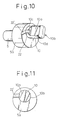
- a lubricant oil groove 22 is formed in the axial direction in the surface in question. This groove is not closed by the general elastic body 21 etc.
- an extended lubricant oil groove 22' is formed in also the side surface of the enlarged diameter portion 5a to facilitate the flow of the lubricant oil into the lubricant oil groove 22.
- a groove like the lubricant oil groove 22 is formed in the annular step portion 11b of the inner surface of the bush 11, but it is not always necessary to form the lubricant oil groove on this side.
- by-pass passages for the lubricant oil such as the lubricant oil grooves 22 and 22' are formed in the surfaces in which the flow of the lubricant oil is blocked by the general elastic bodies 21, 21', and 21'', but in contrast there arises a concern over possible abnormal abrasion of the elastic body 21 or the like at the portion where it comes into contact with the edge portion of the lubricant oil groove 22 or 22' and in the worst case possible breakage.
- a guide surface 24 comprising a smooth hollow is formed in the inner surface of the front housing 2b corresponding to the position 23b of the lubricant oil hole 23, thereby to make the flow of the lubricant oil smooth.
- the value of the centrifugal force acting upon the lubricant oil existing in the lubricant oil hole 23 is mR ⁇ 2 near the position 23b of the lubricant oil hole 23 and 0 near the position 23a where the mass of the unit volume of the mixture of the lubricant oil and the fluid to be compressed (refrigerant) passing in the lubricant oil hole 23 is m.
- the lubricant oil collected in the lower portion of the crank chamber 25 is sucked from the position 23a of the lubricant oil hole 23, and the flow of the lubricant oil to be sent from the position 23a toward the position 23b by the centrifugal force is generated by the rotation of the drive shaft 5.
- the lubricant oil is forcibly circulated, and therefore the main elements of the bearing 4, thrust supporting and rotation preventing mechanism 8, needle bearing 9, etc. are sufficiently lubricated, the lowering of the durability due to the abrasion can be prevented, and thus the reliability is improved.
Landscapes
- Engineering & Computer Science (AREA)
- Mechanical Engineering (AREA)
- General Engineering & Computer Science (AREA)
- Rotary Pumps (AREA)
- Applications Or Details Of Rotary Compressors (AREA)
Applications Claiming Priority (6)
| Application Number | Priority Date | Filing Date | Title |
|---|---|---|---|
| JP5912295 | 1995-03-17 | ||
| JP59122/95 | 1995-03-17 | ||
| JP5912295 | 1995-03-17 | ||
| JP26737795A JP3781460B2 (ja) | 1995-03-17 | 1995-10-16 | スクロール型圧縮機 |
| JP267377/95 | 1995-10-16 | ||
| JP26737795 | 1995-10-16 |
Publications (2)
| Publication Number | Publication Date |
|---|---|
| EP0732503A1 true EP0732503A1 (de) | 1996-09-18 |
| EP0732503B1 EP0732503B1 (de) | 2000-01-05 |
Family
ID=26400162
Family Applications (1)
| Application Number | Title | Priority Date | Filing Date |
|---|---|---|---|
| EP96103961A Expired - Lifetime EP0732503B1 (de) | 1995-03-17 | 1996-03-13 | Spiralverdichter |
Country Status (4)
| Country | Link |
|---|---|
| US (1) | US5681155A (de) |
| EP (1) | EP0732503B1 (de) |
| JP (1) | JP3781460B2 (de) |
| DE (1) | DE69605959T2 (de) |
Cited By (6)
| Publication number | Priority date | Publication date | Assignee | Title |
|---|---|---|---|---|
| CN1082147C (zh) * | 1996-09-20 | 2002-04-03 | 株式会社日立制作所 | 容积型流体机械 |
| EP1113173A3 (de) * | 1999-12-30 | 2002-11-20 | Halla Climate Control Corp. | Integrierter Ölabscheider für Kühlkompressoren |
| WO2006077328A1 (fr) * | 2005-01-21 | 2006-07-27 | V.G.B. (Vulliez Gestion Brevets) | Pompe a vide a cycle de translation circulaire a plusieurs arbres |
| GB2518483A (en) * | 2013-07-31 | 2015-03-25 | Agilent Technologies Inc | Axially compliant orbiting plate scroll and scroll pump comprising the same |
| EP2864635A4 (de) * | 2012-03-23 | 2016-04-13 | Bitzer Kuehlmaschinenbau Gmbh | Spiralverdichter mit schiebeblock |
| CN113494450A (zh) * | 2020-04-07 | 2021-10-12 | 艾默生环境优化技术(苏州)有限公司 | 涡旋压缩机 |
Families Citing this family (24)
| Publication number | Priority date | Publication date | Assignee | Title |
|---|---|---|---|---|
| EP1418337B1 (de) * | 1997-08-29 | 2007-12-19 | Denso Corporation | Spiralverdichter |
| JP4103225B2 (ja) | 1998-06-24 | 2008-06-18 | 株式会社日本自動車部品総合研究所 | 圧縮機 |
| JP2000130363A (ja) * | 1998-10-21 | 2000-05-12 | Denso Corp | スクロール圧縮機 |
| US6126423A (en) * | 1998-11-13 | 2000-10-03 | Ford Global Technologies, Inc. | Preloaded spring mount for crank pin/rotor bearing assembly |
| JP2000220584A (ja) * | 1999-02-02 | 2000-08-08 | Toyota Autom Loom Works Ltd | スクロール型圧縮機 |
| US6328545B1 (en) * | 2000-06-01 | 2001-12-11 | Westinghouse Air Brake Technologies Corporation | Oiless rotary scroll air compressor crankshaft assembly |
| JP2002089462A (ja) | 2000-09-13 | 2002-03-27 | Toyota Industries Corp | スクロール型圧縮機及びスクロール型圧縮機のシール方法 |
| KR100488016B1 (ko) * | 2002-02-28 | 2005-05-06 | 엘지전자 주식회사 | 왕복동식 압축기 |
| KR100507976B1 (ko) * | 2003-07-02 | 2005-08-17 | 삼성전자주식회사 | 용량가변 회전압축기 |
| US20060233654A1 (en) * | 2005-04-11 | 2006-10-19 | Tecumseh Products Company | Compressor with radial compliance mechanism |
| JP2006342793A (ja) * | 2005-05-11 | 2006-12-21 | Denso Corp | 流体機械 |
| EP1983192A4 (de) * | 2006-01-26 | 2016-08-17 | Daikin Ind Ltd | Verfahren zur herstellung einer schiebekomponente eines kompressors und kompressor |
| JP5297181B2 (ja) | 2008-12-24 | 2013-09-25 | 三菱重工業株式会社 | スクロール型圧縮機 |
| JP5506227B2 (ja) * | 2009-03-31 | 2014-05-28 | 三菱重工業株式会社 | スクロール圧縮機 |
| JP5609699B2 (ja) * | 2011-02-15 | 2014-10-22 | 株式会社豊田自動織機 | スクロール型圧縮機 |
| WO2012165431A1 (ja) * | 2011-05-30 | 2012-12-06 | サンデン株式会社 | スクロール型圧縮機 |
| JP5565429B2 (ja) * | 2012-03-29 | 2014-08-06 | 株式会社豊田自動織機 | スクロール圧縮機 |
| JP5880398B2 (ja) * | 2012-11-13 | 2016-03-09 | 株式会社豊田自動織機 | スクロール型圧縮機 |
| CN103851087A (zh) * | 2012-12-06 | 2014-06-11 | 上海日立电器有限公司 | 涡旋压缩机用一体化轴承 |
| JP6149429B2 (ja) * | 2013-03-06 | 2017-06-21 | 株式会社豊田自動織機 | スクロール型圧縮機 |
| JP6394888B2 (ja) * | 2014-11-28 | 2018-09-26 | 株式会社豊田自動織機 | スクロール型圧縮機 |
| WO2018019372A1 (de) * | 2016-07-27 | 2018-02-01 | Bitzer Kühlmaschinenbau Gmbh | Kompressor |
| JP2020051266A (ja) * | 2018-09-25 | 2020-04-02 | 三菱電機株式会社 | スクロール圧縮機 |
| KR102936118B1 (ko) * | 2022-03-22 | 2026-03-09 | 한온시스템 주식회사 | 스크롤 압축기 |
Citations (3)
| Publication number | Priority date | Publication date | Assignee | Title |
|---|---|---|---|---|
| JPH05187366A (ja) * | 1992-01-10 | 1993-07-27 | Mitsubishi Electric Corp | スクロール圧縮機 |
| US5378129A (en) * | 1993-12-06 | 1995-01-03 | Copeland Corporation | Elastic unloader for scroll machines |
| EP0643224A1 (de) * | 1993-09-14 | 1995-03-15 | Nippondenso Co., Ltd. | Spiralverdichter |
Family Cites Families (8)
| Publication number | Priority date | Publication date | Assignee | Title |
|---|---|---|---|---|
| US4314796A (en) * | 1978-09-04 | 1982-02-09 | Sankyo Electric Company Limited | Scroll-type compressor with thrust bearing lubricating and bypass means |
| JPS59103979A (ja) * | 1982-12-03 | 1984-06-15 | Mitsubishi Electric Corp | スクロ−ル圧縮機 |
| JP2730625B2 (ja) * | 1986-05-30 | 1998-03-25 | 松下電器産業株式会社 | スクロール圧縮機 |
| JPH01273890A (ja) * | 1988-04-26 | 1989-11-01 | Matsushita Electric Ind Co Ltd | スクロール型圧縮機 |
| JPH0286976A (ja) * | 1988-09-21 | 1990-03-27 | Diesel Kiki Co Ltd | スクロール流体機械 |
| JP2522213B2 (ja) * | 1988-12-27 | 1996-08-07 | 日本電装株式会社 | 圧縮機 |
| JPH0357893A (ja) * | 1989-07-26 | 1991-03-13 | Mitsubishi Electric Corp | スクロール流体機械 |
| US5076772A (en) * | 1990-06-04 | 1991-12-31 | Carrier Corporation | Slider block radial compliance mechanism with integral deflection bearing |
-
1995
- 1995-10-16 JP JP26737795A patent/JP3781460B2/ja not_active Expired - Lifetime
-
1996
- 1996-03-08 US US08/610,576 patent/US5681155A/en not_active Expired - Lifetime
- 1996-03-13 DE DE69605959T patent/DE69605959T2/de not_active Expired - Lifetime
- 1996-03-13 EP EP96103961A patent/EP0732503B1/de not_active Expired - Lifetime
Patent Citations (4)
| Publication number | Priority date | Publication date | Assignee | Title |
|---|---|---|---|---|
| JPH05187366A (ja) * | 1992-01-10 | 1993-07-27 | Mitsubishi Electric Corp | スクロール圧縮機 |
| US5328342A (en) * | 1992-01-10 | 1994-07-12 | Mitsubishi Denki Kabushiki Kaisha | Scroll compressor with slider contacting an elastic member |
| EP0643224A1 (de) * | 1993-09-14 | 1995-03-15 | Nippondenso Co., Ltd. | Spiralverdichter |
| US5378129A (en) * | 1993-12-06 | 1995-01-03 | Copeland Corporation | Elastic unloader for scroll machines |
Cited By (9)
| Publication number | Priority date | Publication date | Assignee | Title |
|---|---|---|---|---|
| CN1082147C (zh) * | 1996-09-20 | 2002-04-03 | 株式会社日立制作所 | 容积型流体机械 |
| EP1113173A3 (de) * | 1999-12-30 | 2002-11-20 | Halla Climate Control Corp. | Integrierter Ölabscheider für Kühlkompressoren |
| WO2006077328A1 (fr) * | 2005-01-21 | 2006-07-27 | V.G.B. (Vulliez Gestion Brevets) | Pompe a vide a cycle de translation circulaire a plusieurs arbres |
| FR2881189A1 (fr) * | 2005-01-21 | 2006-07-28 | V G B Vulliez Gestion Brevets | Pompe a vide a cycle de translation circulaire a plusieurs arbres |
| EP2864635A4 (de) * | 2012-03-23 | 2016-04-13 | Bitzer Kuehlmaschinenbau Gmbh | Spiralverdichter mit schiebeblock |
| US9920762B2 (en) | 2012-03-23 | 2018-03-20 | Bitzer Kuehlmaschinenbau Gmbh | Scroll compressor with tilting slider block |
| GB2518483A (en) * | 2013-07-31 | 2015-03-25 | Agilent Technologies Inc | Axially compliant orbiting plate scroll and scroll pump comprising the same |
| US9353749B2 (en) | 2013-07-31 | 2016-05-31 | Agilent Technologies, Inc. | Axially compliant orbiting plate scroll and scroll pump comprising the same |
| CN113494450A (zh) * | 2020-04-07 | 2021-10-12 | 艾默生环境优化技术(苏州)有限公司 | 涡旋压缩机 |
Also Published As
| Publication number | Publication date |
|---|---|
| JPH08319981A (ja) | 1996-12-03 |
| DE69605959T2 (de) | 2000-05-18 |
| DE69605959D1 (de) | 2000-02-10 |
| EP0732503B1 (de) | 2000-01-05 |
| JP3781460B2 (ja) | 2006-05-31 |
| US5681155A (en) | 1997-10-28 |
Similar Documents
| Publication | Publication Date | Title |
|---|---|---|
| US5681155A (en) | Scroll type compressor having an elastic body in the driven crank mechanism | |
| CN110905804B (zh) | 涡旋式压缩机 | |
| EP0066457B1 (de) | Mechanismus der Antriebslagerung für eine umlaufende Spirale einer Verdrängermaschine vom Spiraltyp | |
| US5435707A (en) | Scroll-type compressor with an elastically deformable top plate or end plate | |
| JPH07253084A (ja) | スクロール型機械 | |
| US5536152A (en) | Scroll compressor having improved orbital drive mechanism | |
| EP0921316A1 (de) | Spiralverdichter mit Radialführungsstift in Exzenterscheibe | |
| JPH10103243A (ja) | 圧縮機の弁構造 | |
| JP2522213B2 (ja) | 圧縮機 | |
| US20190345941A1 (en) | Scroll compressor | |
| US5427510A (en) | Scroll type compressor having eccentric inclined driving means | |
| JP2000249086A (ja) | スクロール型圧縮機 | |
| JPH08319958A (ja) | スクロール型流体装置 | |
| KR100458799B1 (ko) | 스러스트면을가진스크롤엘레멘트 | |
| EP0480065B1 (de) | Spiralverdichter | |
| US5562436A (en) | Scroll compressor having improved orbital drive mechanism | |
| WO2010073612A1 (ja) | スクロール型圧縮機 | |
| US5362218A (en) | Scroll type compressor with counterweight | |
| JPH0842467A (ja) | スクロール圧縮機 | |
| KR102687327B1 (ko) | 스크롤 압축기 | |
| JP3074980B2 (ja) | スクロール型圧縮機 | |
| US6336798B1 (en) | Rotation preventing mechanism for scroll-type fluid displacement apparatus | |
| JPH09158848A (ja) | スクロール圧縮機 | |
| EP0070617A2 (de) | Einrichtung vom Spiraltyp zum Fördern von Fluid | |
| JP3075328B2 (ja) | 圧縮機 |
Legal Events
| Date | Code | Title | Description |
|---|---|---|---|
| PUAI | Public reference made under article 153(3) epc to a published international application that has entered the european phase |
Free format text: ORIGINAL CODE: 0009012 |
|
| AK | Designated contracting states |
Kind code of ref document: A1 Designated state(s): DE FR GB IT |
|
| 17P | Request for examination filed |
Effective date: 19960926 |
|
| RAP1 | Party data changed (applicant data changed or rights of an application transferred) |
Owner name: KABUSHIKI KAISHA TOYODA JIDOSHOKKI SEISAKUSHO Owner name: DENSO CORPORATION |
|
| 17Q | First examination report despatched |
Effective date: 19970731 |
|
| GRAG | Despatch of communication of intention to grant |
Free format text: ORIGINAL CODE: EPIDOS AGRA |
|
| GRAG | Despatch of communication of intention to grant |
Free format text: ORIGINAL CODE: EPIDOS AGRA |
|
| GRAH | Despatch of communication of intention to grant a patent |
Free format text: ORIGINAL CODE: EPIDOS IGRA |
|
| GRAH | Despatch of communication of intention to grant a patent |
Free format text: ORIGINAL CODE: EPIDOS IGRA |
|
| GRAA | (expected) grant |
Free format text: ORIGINAL CODE: 0009210 |
|
| AK | Designated contracting states |
Kind code of ref document: B1 Designated state(s): DE FR GB IT |
|
| REF | Corresponds to: |
Ref document number: 69605959 Country of ref document: DE Date of ref document: 20000210 |
|
| ITF | It: translation for a ep patent filed | ||
| ET | Fr: translation filed | ||
| PLBE | No opposition filed within time limit |
Free format text: ORIGINAL CODE: 0009261 |
|
| STAA | Information on the status of an ep patent application or granted ep patent |
Free format text: STATUS: NO OPPOSITION FILED WITHIN TIME LIMIT |
|
| 26N | No opposition filed | ||
| REG | Reference to a national code |
Ref country code: GB Ref legal event code: IF02 |
|
| REG | Reference to a national code |
Ref country code: GB Ref legal event code: 732E |
|
| REG | Reference to a national code |
Ref country code: FR Ref legal event code: TP Ref country code: FR Ref legal event code: CD |
|
| PGFP | Annual fee paid to national office [announced via postgrant information from national office to epo] |
Ref country code: FR Payment date: 20130325 Year of fee payment: 18 Ref country code: DE Payment date: 20130306 Year of fee payment: 18 Ref country code: GB Payment date: 20130313 Year of fee payment: 18 |
|
| REG | Reference to a national code |
Ref country code: DE Ref legal event code: R119 Ref document number: 69605959 Country of ref document: DE |
|
| GBPC | Gb: european patent ceased through non-payment of renewal fee |
Effective date: 20140313 |
|
| REG | Reference to a national code |
Ref country code: FR Ref legal event code: ST Effective date: 20141128 |
|
| REG | Reference to a national code |
Ref country code: DE Ref legal event code: R119 Ref document number: 69605959 Country of ref document: DE Effective date: 20141001 |
|
| PG25 | Lapsed in a contracting state [announced via postgrant information from national office to epo] |
Ref country code: GB Free format text: LAPSE BECAUSE OF NON-PAYMENT OF DUE FEES Effective date: 20140313 Ref country code: FR Free format text: LAPSE BECAUSE OF NON-PAYMENT OF DUE FEES Effective date: 20140331 Ref country code: DE Free format text: LAPSE BECAUSE OF NON-PAYMENT OF DUE FEES Effective date: 20141001 |
|
| PGFP | Annual fee paid to national office [announced via postgrant information from national office to epo] |
Ref country code: IT Payment date: 20150327 Year of fee payment: 20 |