EP0732801A2 - Appareil pour mettre en marche un moteur à reluctance commuté - Google Patents
Appareil pour mettre en marche un moteur à reluctance commuté Download PDFInfo
- Publication number
- EP0732801A2 EP0732801A2 EP95307187A EP95307187A EP0732801A2 EP 0732801 A2 EP0732801 A2 EP 0732801A2 EP 95307187 A EP95307187 A EP 95307187A EP 95307187 A EP95307187 A EP 95307187A EP 0732801 A2 EP0732801 A2 EP 0732801A2
- Authority
- EP
- European Patent Office
- Prior art keywords
- phases
- rotor
- switched reluctance
- reluctance motor
- phase
- Prior art date
- Legal status (The legal status is an assumption and is not a legal conclusion. Google has not performed a legal analysis and makes no representation as to the accuracy of the status listed.)
- Granted
Links
Images


Classifications
-
- H—ELECTRICITY
- H02—GENERATION; CONVERSION OR DISTRIBUTION OF ELECTRIC POWER
- H02P—CONTROL OR REGULATION OF ELECTRIC MOTORS, ELECTRIC GENERATORS OR DYNAMO-ELECTRIC CONVERTERS; CONTROLLING TRANSFORMERS, REACTORS OR CHOKE COILS
- H02P1/00—Arrangements for starting electric motors or dynamo-electric converters
- H02P1/16—Arrangements for starting electric motors or dynamo-electric converters for starting dynamo-electric motors or dynamo-electric converters
- H02P1/163—Arrangements for starting electric motors or dynamo-electric converters for starting dynamo-electric motors or dynamo-electric converters for starting an individual reluctance motor
-
- H—ELECTRICITY
- H02—GENERATION; CONVERSION OR DISTRIBUTION OF ELECTRIC POWER
- H02P—CONTROL OR REGULATION OF ELECTRIC MOTORS, ELECTRIC GENERATORS OR DYNAMO-ELECTRIC CONVERTERS; CONTROLLING TRANSFORMERS, REACTORS OR CHOKE COILS
- H02P25/00—Arrangements or methods for the control of AC motors characterised by the kind of AC motor or by structural details
- H02P25/02—Arrangements or methods for the control of AC motors characterised by the kind of AC motor or by structural details characterised by the kind of motor
- H02P25/08—Reluctance motors
- H02P25/092—Converters specially adapted for controlling reluctance motors
- H02P25/0925—Converters specially adapted for controlling reluctance motors wherein the converter comprises only one switch per phase
-
- H—ELECTRICITY
- H02—GENERATION; CONVERSION OR DISTRIBUTION OF ELECTRIC POWER
- H02P—CONTROL OR REGULATION OF ELECTRIC MOTORS, ELECTRIC GENERATORS OR DYNAMO-ELECTRIC CONVERTERS; CONTROLLING TRANSFORMERS, REACTORS OR CHOKE COILS
- H02P6/00—Arrangements for controlling synchronous motors or other dynamo-electric motors using electronic commutation dependent on the rotor position; Electronic commutators therefor
- H02P6/14—Electronic commutators
- H02P6/16—Circuit arrangements for detecting position
- H02P6/18—Circuit arrangements for detecting position without separate position detecting elements
Definitions
- the invention relates to switched reluctance ("SR") motors and particularly to an apparatus for determining which phase of an SR motor to commutate at a given moment.
- SR switched reluctance
- SR motors have multiple poles on both the stator and the rotor. There are windings or coils on the stator poles and each pair of windings on diametrically opposite stator poles is connected in series to form an electrically independent phase of the SR motor. There are no windings or magnets on the rotor.
- the rotor is made of a magnetically permeable material such as, for example, a ferrous alloy.
- the rise time of current in a particular stator phase of an SR motor varies with the inductance of the phase.
- the inductance of a particular phase of an SR motor is a function of the angular position of the rotor poles with respect to the stator poles comprising the phase. Therefore, the position of the rotor poles can be detected by measuring the rise times of the current in each of the respective stator phases.
- V the voltage across the phase
- L the inductance of the phase
- dI/dT the change in current with respect to time.
- the rise time of current in all three phases is tested and correlated to determine which phase has the highest, intermediate and lowest inductance (these are indicative of the exact position of the rotor poles with respect to the stator).
- the order of inductances is matched to a ROM based look-up table to determine which phase should be energized or commutated first.
- the invention provides an electronic circuit for starting a switched reluctance motor.
- the motor has a rotor mounted for rotation about an axis and the rotor includes a plurality of rotor poles.
- the motor also has a stator surrounding the rotor.
- the stator includes at least three stator pole pairs and at least three stator coils or windings wound around the respective stator pole pairs to form at least three electrically independent stator phases.
- the circuit of the invention employs a microprocessor and support circuitry in combination with a field programmable gate array.
- the use of a gate array in combination with a microprocessor reduces the number of components necessary to practice the invention and reduces the space requirements of the circuit.
- the electronic circuit includes pulse means for supplying a seek current to each phase of the motor when the rotor is at rest, timing means for measuring the rise time required for the seek current in each of the phases to reach a predetermined seek current threshold, comparing means for comparing the rise times of the seek currents in the respective phases, and run means connected to the comparing means for sequentially energizing or commutating the phases in response to the comparison of seek times.
- the pulse means sends a low power seek current pulse to each phase of the SR motor.
- the current level in each phase is monitored and is measured against time (employing a clock in combination with a series of counters) and a rise time is established for the current in each phase to reach a predetermined seek current threshold, which is equal to roughly 2% to 3% of the maximum running current.
- the rise times are indicative of the inductances of the respective phases of the SR motor.
- An order of phase inductances (highest to lowest) is established and compared with combinations of phase inductances stored in a Read-Only-Memory (ROM) based look-up table.
- the ROM outputs a control signal to energize a particular phase of the motor.
- a principal advantage of the invention is the use of a microprocessor and field programmable gate array to detect rotor position without the use of a discrete rotor position sensor.
- Another advantage of the invention is the provision of a simple circuit for starting and driving a switched reluctance motor at low speeds.
- Another advantage of the invention is the provision of a circuit that starts a switched reluctance motor and that limits the reverse rotation of the rotor upon starting to a maximum of 2° to 3°.
- FIGURE 1 is a schematic view of a switched reluctance motor showing, in cross-section, the stator and the rotor of the switched reluctance motor.
- FIGURE 2 is a schematic diagram of the electronic circuit for starting the switched reluctance motor, with a simplified illustration of the phase leg of the circuit.
- FIGURE 3 is a graphic chart illustrating the phase inductances relative to the rotor pole positions, the order, from highest to lowest, of phase inductances relative to rotor pole positions, and the phase which is energized first in response to a particular order of phase inductances.
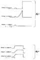
- FIGURE 4 is a graphic chart illustrating the phase currents versus time showing the simultaneous pulses being applied to each of the three windings.
- FIGURE 5 is a graphic chart illustrating the phase currents versus time with the slow ramp up of the selected phase and then the full run current being applied to the next appropriate phase.
- FIGURE 1 of the drawings Shown in FIGURE 1 of the drawings is a schematic view of a switched reluctance motor 10.
- the switched reluctance motor 10 includes a rotor 14 mounted for rotation about an his 18.
- the rotor 14 includes four rotor poles 22, 26, 30, and 34.
- the rotor poles 22, 26, 30, and 34 are evenly spaced about the axis 18 and extend radially outward from the rotor 14 relative to the axis 18.
- the motor 10 also includes a stator 38 surrounding the rotor 14.
- the stator 38 has an inner surface 42 and six stator poles 46, 50, 54, 58, 62 and 66, extending from the inner surface 42 inwardly toward the rotor axis 18.
- the stator poles 46, 50, 54, 58, 62 and 66 are evenly spaced about the inner surface 42 of the stator 38.
- the switched reluctance motor 10 shown in FIGURE 1 is referred to as 6/4 (six stator pole to four rotor pole ratio) switched reluctance motor. While this description will refer to the operation of the invention in terms of a 6/4 SR motor, it should be understood that any switched reluctance motor having any number of stator poles and rotor poles can be controlled with the circuit disclosed herein.
- the SR motor 10 also includes windings or coils 70, 74, 78, 82, 86 and 90, on the stator poles 46, 50, 54, 58, 62 and 66, respectively.
- the windings are made of a conductor of a precise gauge which is wound around the stator pole a precise number of times or turns.
- the gauge of the wire and the number of turns vary depending upon the application. While the description applies equally to any SR motor using any gauge wire or having any number of turns, in the embodiment shown in the drawings, each stator pole has 98 turns and the motor is referred to as a 98 turn 6/4 SR motor.
- stator poles 46, 50, 54, 58, 62 and 66 are connected in series to form three electrically independent phases 1, 2, and 3 of the SR motor 10.
- the windings 70 and 82 on stator poles 46 and 58, respectively form pole pairs which together form Phase 1
- the windings 74 and 86 on stator poles 50 and 62, respectively form pole pairs which together form Phase 2
- the windings 78 and 90 on stator poles 54 and 66 respectively, form pole pairs which together form Phase 3.
- the rotor 14 is made of ferromagnetic material, energizing a particular phase of the motor 10 results in the formation of a magnetic attraction between the windings on the stator pole pairs comprising the energized phase and the rotor poles closest to the stator poles of the energized phase.
- the rotational direction and speed of the rotor 14 can be precisely controlled.
- FIGURE 2 illustrates a schematic diagram of an electronic circuit 94 for starting the SR motor 10 and energizing the SR motor 10 at low rotor speeds.
- the circuit 94 is connected to the motor 10 which is shown schematically as phase winding 1 (only one of the three is shown) connected between a positive supply voltage (+Vs) and a negative supply voltage (-Vs) via a switch or relay 98.
- phase winding 1 (only one of the three is shown) connected between a positive supply voltage (+Vs) and a negative supply voltage (-Vs) via a switch or relay 98.
- This portion of the circuit 94 is duplicated as many times as there are phases on the particular SR motor 10.
- this portion of the circuit 94 is repeated three times, i.e., there are three phase windings connected between the positive and negative supply voltages via three switches or relays 98. Only one of these circuit portions will be shown and described in detail.
- the circuit 94 for controlling the motor 10 includes current sensing means connected to the phase winding 1. While any conventional current sensor is appropriate, the sensing means of the embodiment shown in FIGURE 2 is a current sensor 102 which is mounted adjacent to the phase current pathway. In the preferred embodiment, a current sensor sold by the LEM Company is used. The current sensor outputs a voltage which is proportional to current. Current flowing through the phase 1 generates a corresponding signal in the sensor 102. The current sensor 102 prevents excess current loading in the phase 1.
- the current sensing means also includes a comparator (not shown) connected to the current sensor 102. The comparator compares the analog signal (voltage) from the current sensor to a reference voltage. When the sensor signal exceeds the reference signal, a latch signal is input to the counter 110, which is explained below.
- the circuit 94 also includes a field programmable gate array 104 and a microprocessor 106 connected to the gate array 104. While any appropriate gate array and microprocessor could be used, the circuit 94 uses gate array XC3090-70PC84C manufactured by XILINX, Inc and microprocessor DSP56001RC33 manufactured by Motorola, Inc.
- the gate array 104 is defined and programmed in a manner consistent with this description and in a manner conventional in the art. Conventional programming hardware recommended by the manufacturer of gate array 104 is also used.
- the microprocessor 106 is programmed in a manner consistent with this description and conventional in the art, with conventional programming hardware recommended by the device manufacturer.
- the field programmable gate array 104 includes a bank of counters 110.
- the counters 110 are connected to the current sensor 102 via the comparator (not shown).
- the counters 110 receive the digital output from the comparator (not shown) and measure the amount of time required for the current in the phase winding to reach a predetermined current threshold level, i.e., the seek current rise time.
- the counters 110 are set to zero when the seek current pulse is started.
- other timing devices such as an analog capacitor, could be used instead of the counters 110.
- the microprocessor 106 includes comparing means connected to the counters 110.
- the comparing means compares the seek current rise times from the phase windings and establishes a priority sequence determined by which of the phases 1, 2, or 3, has the lowest seek current rise time, which has the intermediate seek current rise time and which has the highest seek current rise time.
- the comparing means includes a comparator 114 connected to a read-only-memory (ROM) based memory array 118.
- the microprocessor 106 also includes energizing means connected to the comparator 114.
- the energizing means is a run signal generator 122 which generates commutation or run control signals to energize a selected phase 1, 2, or 3, based upon the order of priority of the seek current rise times.
- the microprocessor 106 also includes pulse means connected to the counters 110.
- the pulse means is a pulse signal generator 126 which generates seek pulse control signals.
- the microprocessor 106 also includes switch operating means connected to counters 110, pulse signal generator 126, run signal generator 122 and phase switches 98.
- the switch operating means is a switch controller 130.
- the switch controller 130 receives as inputs the pulse control signals and commutation control signals from the pulse signal generator 126 and run signal generator 122, respectively, and activates the phase switch 98 in response thereto to generate either a seek current pulse or a commutation current in the phase winding 1. In other embodiments, these functions could be accomplished by logic devices instead of the microprocessor 106.
- the pulse signal generator 126 of the microprocessor 106 sends control signals to the switch controller 130 which operates the switches 98 of the respective phases, 1, 2 and 3, in such a way as to energize the phases with seek current pulses (see Fig. 4).
- the seek current pulses are preferably low power and do not generate a sufficiently strong magnetic field in the phases, 1, 2 and 3, to result in rotation of the rotor 14.
- the current in the phase windings, 1, 2, and 3, resulting from the seek current pulses is monitored by the current sensor 102 and is input to the counters 110 of the field programmable gate array.
- the counters 110 monitor the phase current to calculate the seek current rise times of the seek current in the phases.
- the rise time of the current in a particular phase will vary with the inductance of the phase and the inductance of the phase is directly related to the proximity of the rotor poles 22, 26, 30, and 34, to the stator poles 46 and 58, 50 and 62, or 54 and 66, comprising the phases 1, 2 or 3, respectively.
- the seek current rise times of the current in the phases 1, 2 and 3 are transmitted from the counters 110 to the comparator 114.
- the comparator 114 determines which phase 1, 2 or 3 has the highest, the middle, and the lowest phase inductance.
- the ROM-based memory array 118 receives as an input the order of phase inductances and generates as an output a signal corresponding to a particular phase that is the first phase to be fired or energized with the high power run current.
- FIGURE 3 is a chart which illustrates the variation in phase inductances with respect to position of the rotor poles 22, 26, 30, and 34, and the results generated by the ROM-based memory array 118 given a particular order of phase inductances.
- phase 1 will have the highest inductance
- phase 3 will have the middle level inductance
- phase 2 will have the lowest inductance.
- FIGURE 4 is an illustration of possible seek pulse currents versus time.
- phase 3 will be the phase that is energized with the run current first.
- current is applied to phase 3
- Phase 3 was energized because energizing phase 1 would not result in rotor movement (or perhaps would result in a slight reverse, i.e., counter-clockwise movement) since the rotor poles 22 and 30 are already aligned (or are nearly aligned) with the stator poles comprising phase 1.
- energizing phase 2 would result in reverse (counter-clockwise) rotation of the rotor 14 with respect to the stator 38 because an attractive magnetic force would exist between stator poles 50 and 62 and the closest rotor poles 26 and 34.
Landscapes
- Engineering & Computer Science (AREA)
- Power Engineering (AREA)
- Control Of Electric Motors In General (AREA)
Applications Claiming Priority (2)
| Application Number | Priority Date | Filing Date | Title |
|---|---|---|---|
| US08/404,471 US5497064A (en) | 1995-03-14 | 1995-03-14 | Apparatus for starting a switched reluctance motor |
| US404471 | 1995-03-14 |
Publications (3)
| Publication Number | Publication Date |
|---|---|
| EP0732801A2 true EP0732801A2 (fr) | 1996-09-18 |
| EP0732801A3 EP0732801A3 (fr) | 1996-10-09 |
| EP0732801B1 EP0732801B1 (fr) | 1999-01-07 |
Family
ID=23599737
Family Applications (1)
| Application Number | Title | Priority Date | Filing Date |
|---|---|---|---|
| EP95307187A Expired - Lifetime EP0732801B1 (fr) | 1995-03-14 | 1995-10-11 | Appareil pour mettre en marche un moteur à reluctance commuté |
Country Status (6)
| Country | Link |
|---|---|
| US (1) | US5497064A (fr) |
| EP (1) | EP0732801B1 (fr) |
| CA (1) | CA2159781C (fr) |
| DE (1) | DE69507125T2 (fr) |
| IE (1) | IE76128B1 (fr) |
| MX (1) | MX9504595A (fr) |
Cited By (2)
| Publication number | Priority date | Publication date | Assignee | Title |
|---|---|---|---|---|
| DE10156243A1 (de) * | 2001-11-15 | 2003-06-05 | Bosch Gmbh Robert | Elektronisch kommutierter Motor |
| EP1615333A1 (fr) * | 2004-07-06 | 2006-01-11 | Newage International Limited | Détermination de la position du rotor d'une machine electrique |
Families Citing this family (18)
| Publication number | Priority date | Publication date | Assignee | Title |
|---|---|---|---|---|
| US5712539A (en) * | 1995-06-07 | 1998-01-27 | Exabyte Corporation | Digital acoustic noise reduction in electric motors driven by switching power amplifiers |
| US5783940A (en) * | 1996-12-23 | 1998-07-21 | Dana Corporation | Encoder circuit for determining the position of a rotor of a multiphase motor |
| US6091222A (en) | 1997-06-30 | 2000-07-18 | Stmicroelectronics, Inc. | Statistical phase detection and go start-up algorithm |
| US5838129A (en) * | 1997-08-13 | 1998-11-17 | Luh; Yih-Ping | Driving method for multiple-pole motors with optimum driving waveform |
| US6107772A (en) * | 1997-09-26 | 2000-08-22 | Dana Corporation | Sensorless switched reluctance motor control |
| GB2329770B (en) * | 1997-09-26 | 2002-02-20 | Dana Corp | Sensorless switched reluctance motor control |
| GB2367197B (en) * | 1997-09-26 | 2002-05-15 | Dana Corp | Sensorless switched reluctance motor control |
| IT1307378B1 (it) * | 1999-08-06 | 2001-11-06 | Askoll Holding Srl | Dispositivo elettronico di alimentazione di un motore sincrono conrotore a magneti permanenti a due coppie di poli. |
| US6246193B1 (en) | 1999-08-26 | 2001-06-12 | Tridelta Industries, Inc. | Encoderless rotor position detection method and apparatus |
| GB0100552D0 (en) | 2001-01-09 | 2001-02-21 | Switched Reluctance Drives Ltd | A method and system for determining rotor position in a switched reluctance machine |
| US6653811B2 (en) | 2001-08-08 | 2003-11-25 | A. O. Smith Corporation | Switched reluctance motor and method and apparatus for aligning the rotor thereof |
| US20030042864A1 (en) * | 2001-08-31 | 2003-03-06 | Delphi Technologies, Inc. | Switched-reluctance motor control |
| DE10162380A1 (de) * | 2001-12-19 | 2003-07-03 | Bosch Gmbh Robert | Verfahren zum Starten eines bürstenlosen Gleichstrommotors |
| EP1678818A1 (fr) * | 2003-09-30 | 2006-07-12 | Emerson Electric Co. | Detection de position pour machine a reluctance commutee |
| US7598683B1 (en) | 2007-07-31 | 2009-10-06 | Lsi Industries, Inc. | Control of light intensity using pulses of a fixed duration and frequency |
| US8903577B2 (en) | 2009-10-30 | 2014-12-02 | Lsi Industries, Inc. | Traction system for electrically powered vehicles |
| US8604709B2 (en) | 2007-07-31 | 2013-12-10 | Lsi Industries, Inc. | Methods and systems for controlling electrical power to DC loads |
| US10135377B2 (en) * | 2016-06-14 | 2018-11-20 | Arm Ltd. | Method and apparatus for operating an electric motor |
Family Cites Families (23)
| Publication number | Priority date | Publication date | Assignee | Title |
|---|---|---|---|---|
| DE2353594C2 (de) * | 1973-10-25 | 1975-10-09 | Siemens Ag, 1000 Berlin Und 8000 Muenchen | Verfahren und Anordnung zur Ermittlung des Läuferwinkels einer Synchronmaschine |
| IT1034371B (it) * | 1974-05-02 | 1979-09-10 | Ibm | Sistema di controllo per un motore a passi |
| GB1591346A (en) * | 1977-03-30 | 1981-06-17 | Chloride Group Ltd | Reluctance electric motor drive systems |
| GB8307047D0 (en) * | 1983-03-15 | 1983-04-20 | Hill R J | Stepping motors and drive circuits |
| US4670698A (en) * | 1983-12-02 | 1987-06-02 | Imec Corporation | Adaptive induction motor controller |
| US4876491A (en) * | 1986-07-01 | 1989-10-24 | Conner Peripherals, Inc. | Method and apparatus for brushless DC motor speed control |
| SE455034B (sv) * | 1986-10-10 | 1988-06-13 | Ems Electronic Motor Systems | Drivkrets for en reluktansmotor |
| SE454928B (sv) * | 1986-10-10 | 1988-06-06 | Ems Electronic Motor Systems | Drivanordning for en reluktansmotor |
| US4746850A (en) * | 1987-02-12 | 1988-05-24 | Westinghouse Electric Corp. | Start-up system for a synchronous motor drive |
| US4739240A (en) * | 1987-04-29 | 1988-04-19 | General Electric Company | Commutator for switched reluctance drive |
| US4772839A (en) * | 1987-10-27 | 1988-09-20 | General Electric Company | Rotor position estimator for switched reluctance motor |
| US4992710A (en) * | 1989-09-27 | 1991-02-12 | Seagate Technology, Inc. | Position detection for a brushless DC motor with sample time optimization |
| US5001405A (en) * | 1989-09-27 | 1991-03-19 | Seagate Technology, Inc. | Position detection for a brushless DC motor |
| US5051680A (en) * | 1989-12-08 | 1991-09-24 | Sundstrand Corporation | Simple starting sequence for variable reluctance motors without rotor position sensor |
| AU633738B2 (en) * | 1990-06-20 | 1993-02-04 | Matsushita Electric Industrial Co., Ltd. | Brushless DC motor |
| US5028852A (en) * | 1990-06-21 | 1991-07-02 | Seagate Technology, Inc. | Position detection for a brushless DC motor without hall effect devices using a time differential method |
| US5117165A (en) * | 1990-06-29 | 1992-05-26 | Seagate Technology, Inc. | Closed-loop control of a brushless DC motor from standstill to medium speed |
| US5015939A (en) * | 1990-08-10 | 1991-05-14 | Synektron Corporation | Control circuit for switched reluctance motor |
| US5017845A (en) * | 1990-10-05 | 1991-05-21 | Sgs-Thomson Microelectronics, Inc. | Brushless direct current motor starting and operating apparatus and method |
| US5097190A (en) * | 1991-02-11 | 1992-03-17 | General Electric Company | Rotor position estimator for a switched reluctance machine |
| US5268627A (en) * | 1992-02-11 | 1993-12-07 | Goldstar Co., Ltd. | Start assisting device for high speed reluctance motor |
| US5291115A (en) * | 1992-09-25 | 1994-03-01 | The Texas A&M University System | Method and apparatus for sensing the rotor position of a switched reluctance motor without a shaft position sensor |
| US5363032A (en) * | 1993-05-12 | 1994-11-08 | Sundstrand Corporation | Sensorless start of synchronous machine |
-
1995
- 1995-03-14 US US08/404,471 patent/US5497064A/en not_active Expired - Lifetime
- 1995-09-29 IE IE950764A patent/IE76128B1/en not_active IP Right Cessation
- 1995-10-03 CA CA002159781A patent/CA2159781C/fr not_active Expired - Fee Related
- 1995-10-11 EP EP95307187A patent/EP0732801B1/fr not_active Expired - Lifetime
- 1995-10-11 DE DE69507125T patent/DE69507125T2/de not_active Expired - Fee Related
- 1995-10-31 MX MX9504595A patent/MX9504595A/es unknown
Non-Patent Citations (1)
| Title |
|---|
| None |
Cited By (4)
| Publication number | Priority date | Publication date | Assignee | Title |
|---|---|---|---|---|
| US6822355B2 (en) | 2000-11-05 | 2004-11-23 | Robert Bosch Gmbh | Electronically-commutated motor |
| DE10156243A1 (de) * | 2001-11-15 | 2003-06-05 | Bosch Gmbh Robert | Elektronisch kommutierter Motor |
| EP1615333A1 (fr) * | 2004-07-06 | 2006-01-11 | Newage International Limited | Détermination de la position du rotor d'une machine electrique |
| US7233123B2 (en) | 2004-07-06 | 2007-06-19 | Cummins Generator Technologies Limited | Electrical machine rotor position identification |
Also Published As
| Publication number | Publication date |
|---|---|
| CA2159781A1 (fr) | 1996-09-15 |
| EP0732801A3 (fr) | 1996-10-09 |
| CA2159781C (fr) | 1999-04-06 |
| US5497064A (en) | 1996-03-05 |
| DE69507125D1 (de) | 1999-02-18 |
| IE76128B1 (en) | 1997-10-08 |
| IE950764A1 (en) | 1996-09-18 |
| EP0732801B1 (fr) | 1999-01-07 |
| DE69507125T2 (de) | 1999-07-22 |
| MX9504595A (es) | 1997-05-31 |
Similar Documents
| Publication | Publication Date | Title |
|---|---|---|
| US5497064A (en) | Apparatus for starting a switched reluctance motor | |
| US5001405A (en) | Position detection for a brushless DC motor | |
| EP0732800B1 (fr) | Moteur à réluctance variable muni d'une détection de la position du rotor | |
| US4992710A (en) | Position detection for a brushless DC motor with sample time optimization | |
| JP2635237B2 (ja) | ホール効果デバイスなしに時間差方法を用いたブラシレス直流モータ用位置検出装置 | |
| US5254914A (en) | Position detection for a brushless DC motor without Hall effect devices using a mutual inductance detection method | |
| US5783940A (en) | Encoder circuit for determining the position of a rotor of a multiphase motor | |
| EP0753933A1 (fr) | Procede de demarrage d'un moteur electrique synchrone a aimants permanents a l'aide d'un detecteur de position angulaire et dispositif de commande de ce moteur | |
| US6153956A (en) | Switched reluctance position sensing | |
| US5537019A (en) | Switched reluctance motor providing rotor position detection at high speeds without a separate rotor shaft position sensor | |
| JPH03183394A (ja) | デジタルフィルタリングシステムを使用してロータ用位置センサなしに多相ブラシュレスモータを制御する方法 | |
| EP0072597B1 (fr) | Moteur à courant continu sans balai à auto-démarrage | |
| US5838122A (en) | Motor initialization method and apparatus | |
| US20020047351A1 (en) | Method of starting brushless DC motor on the basis of induced voltage in armature coil for detection of position of rotor | |
| EP0507835B1 (fr) | Methode et dispositif pour la mise en marche d'une machine electrique a reluctance variable | |
| KR100572164B1 (ko) | 정류제어기 | |
| KR20010030759A (ko) | 무 브러시 다상 직류 모터의 회전각도 검출 장치 | |
| US20040108826A1 (en) | Method for characterizing a rotating electromagnetic machine | |
| JPS61177198A (ja) | 永久磁化した回転子を備えたモータ駆動装置 | |
| JPH0331722A (ja) | 指示装置の指針の絶対位置の検出方法及び指示装置 | |
| JP3654003B2 (ja) | センサレスモータの回転子位置検出装置 | |
| KR100282366B1 (ko) | 센서리스 비엘디씨(bldc) 모터의 구동방법 | |
| CA1082302A (fr) | Commutateur electronique pour moteur a courant continu, et methode de commutation sans capteurs de position | |
| JPH04368489A (ja) | ブラシレスモータの回転子位置検出方法 | |
| JPS62131787A (ja) | 無整流子電動機の起動装置 |
Legal Events
| Date | Code | Title | Description |
|---|---|---|---|
| PUAI | Public reference made under article 153(3) epc to a published international application that has entered the european phase |
Free format text: ORIGINAL CODE: 0009012 |
|
| PUAL | Search report despatched |
Free format text: ORIGINAL CODE: 0009013 |
|
| AK | Designated contracting states |
Kind code of ref document: A2 Designated state(s): DE FR GB IT |
|
| AK | Designated contracting states |
Kind code of ref document: A3 Designated state(s): DE FR GB IT |
|
| 17P | Request for examination filed |
Effective date: 19960925 |
|
| 17Q | First examination report despatched |
Effective date: 19970626 |
|
| GRAG | Despatch of communication of intention to grant |
Free format text: ORIGINAL CODE: EPIDOS AGRA |
|
| GRAG | Despatch of communication of intention to grant |
Free format text: ORIGINAL CODE: EPIDOS AGRA |
|
| GRAH | Despatch of communication of intention to grant a patent |
Free format text: ORIGINAL CODE: EPIDOS IGRA |
|
| GRAH | Despatch of communication of intention to grant a patent |
Free format text: ORIGINAL CODE: EPIDOS IGRA |
|
| GRAA | (expected) grant |
Free format text: ORIGINAL CODE: 0009210 |
|
| AK | Designated contracting states |
Kind code of ref document: B1 Designated state(s): DE FR GB IT |
|
| ITF | It: translation for a ep patent filed | ||
| REF | Corresponds to: |
Ref document number: 69507125 Country of ref document: DE Date of ref document: 19990218 |
|
| ET | Fr: translation filed | ||
| PLBE | No opposition filed within time limit |
Free format text: ORIGINAL CODE: 0009261 |
|
| STAA | Information on the status of an ep patent application or granted ep patent |
Free format text: STATUS: NO OPPOSITION FILED WITHIN TIME LIMIT |
|
| 26N | No opposition filed | ||
| REG | Reference to a national code |
Ref country code: GB Ref legal event code: IF02 |
|
| PGFP | Annual fee paid to national office [announced via postgrant information from national office to epo] |
Ref country code: GB Payment date: 20051005 Year of fee payment: 11 |
|
| PGFP | Annual fee paid to national office [announced via postgrant information from national office to epo] |
Ref country code: FR Payment date: 20051017 Year of fee payment: 11 |
|
| PGFP | Annual fee paid to national office [announced via postgrant information from national office to epo] |
Ref country code: DE Payment date: 20051130 Year of fee payment: 11 |
|
| PGFP | Annual fee paid to national office [announced via postgrant information from national office to epo] |
Ref country code: IT Payment date: 20061031 Year of fee payment: 12 |
|
| PG25 | Lapsed in a contracting state [announced via postgrant information from national office to epo] |
Ref country code: DE Free format text: LAPSE BECAUSE OF NON-PAYMENT OF DUE FEES Effective date: 20070501 |
|
| GBPC | Gb: european patent ceased through non-payment of renewal fee |
Effective date: 20061011 |
|
| REG | Reference to a national code |
Ref country code: FR Ref legal event code: ST Effective date: 20070629 |
|
| PG25 | Lapsed in a contracting state [announced via postgrant information from national office to epo] |
Ref country code: GB Free format text: LAPSE BECAUSE OF NON-PAYMENT OF DUE FEES Effective date: 20061011 |
|
| PG25 | Lapsed in a contracting state [announced via postgrant information from national office to epo] |
Ref country code: FR Free format text: LAPSE BECAUSE OF NON-PAYMENT OF DUE FEES Effective date: 20061031 |
|
| PG25 | Lapsed in a contracting state [announced via postgrant information from national office to epo] |
Ref country code: IT Free format text: LAPSE BECAUSE OF NON-PAYMENT OF DUE FEES Effective date: 20071011 |