EP0732899B1 - Technique automatique permettant de localiser des reperes de cliches a fixation externe dans des images en volume de la tete - Google Patents
Technique automatique permettant de localiser des reperes de cliches a fixation externe dans des images en volume de la tete Download PDFInfo
- Publication number
- EP0732899B1 EP0732899B1 EP95904833A EP95904833A EP0732899B1 EP 0732899 B1 EP0732899 B1 EP 0732899B1 EP 95904833 A EP95904833 A EP 95904833A EP 95904833 A EP95904833 A EP 95904833A EP 0732899 B1 EP0732899 B1 EP 0732899B1
- Authority
- EP
- European Patent Office
- Prior art keywords
- voxels
- candidate
- centroid
- image
- voxel
- Prior art date
- Legal status (The legal status is an assumption and is not a legal conclusion. Google has not performed a legal analysis and makes no representation as to the accuracy of the status listed.)
- Expired - Lifetime
Links
Images



Classifications
-
- A—HUMAN NECESSITIES
- A61—MEDICAL OR VETERINARY SCIENCE; HYGIENE
- A61B—DIAGNOSIS; SURGERY; IDENTIFICATION
- A61B6/00—Apparatus or devices for radiation diagnosis; Apparatus or devices for radiation diagnosis combined with radiation therapy equipment
- A61B6/12—Arrangements for detecting or locating foreign bodies
-
- A—HUMAN NECESSITIES
- A61—MEDICAL OR VETERINARY SCIENCE; HYGIENE
- A61B—DIAGNOSIS; SURGERY; IDENTIFICATION
- A61B6/00—Apparatus or devices for radiation diagnosis; Apparatus or devices for radiation diagnosis combined with radiation therapy equipment
- A61B6/58—Testing, adjusting or calibrating thereof
- A61B6/582—Calibration
- A61B6/583—Calibration using calibration phantoms
-
- A—HUMAN NECESSITIES
- A61—MEDICAL OR VETERINARY SCIENCE; HYGIENE
- A61B—DIAGNOSIS; SURGERY; IDENTIFICATION
- A61B90/00—Instruments, implements or accessories specially adapted for surgery or diagnosis and not covered by any of the groups A61B1/00 - A61B50/00, e.g. for luxation treatment or for protecting wound edges
- A61B90/10—Instruments, implements or accessories specially adapted for surgery or diagnosis and not covered by any of the groups A61B1/00 - A61B50/00, e.g. for luxation treatment or for protecting wound edges for stereotaxic surgery, e.g. frame-based stereotaxis
-
- A—HUMAN NECESSITIES
- A61—MEDICAL OR VETERINARY SCIENCE; HYGIENE
- A61B—DIAGNOSIS; SURGERY; IDENTIFICATION
- A61B90/00—Instruments, implements or accessories specially adapted for surgery or diagnosis and not covered by any of the groups A61B1/00 - A61B50/00, e.g. for luxation treatment or for protecting wound edges
- A61B90/39—Markers, e.g. radio-opaque or breast lesions markers
-
- G—PHYSICS
- G01—MEASURING; TESTING
- G01R—MEASURING ELECTRIC VARIABLES; MEASURING MAGNETIC VARIABLES
- G01R33/00—Arrangements or instruments for measuring magnetic variables
- G01R33/20—Arrangements or instruments for measuring magnetic variables involving magnetic resonance
- G01R33/44—Arrangements or instruments for measuring magnetic variables involving magnetic resonance using nuclear magnetic resonance [NMR]
- G01R33/48—NMR imaging systems
- G01R33/58—Calibration of imaging systems, e.g. using test probes, Phantoms; Calibration objects or fiducial markers such as active or passive RF coils surrounding an MR active material
-
- G—PHYSICS
- G06—COMPUTING OR CALCULATING; COUNTING
- G06T—IMAGE DATA PROCESSING OR GENERATION, IN GENERAL
- G06T7/00—Image analysis
- G06T7/0002—Inspection of images, e.g. flaw detection
- G06T7/0012—Biomedical image inspection
-
- G—PHYSICS
- G06—COMPUTING OR CALCULATING; COUNTING
- G06T—IMAGE DATA PROCESSING OR GENERATION, IN GENERAL
- G06T7/00—Image analysis
- G06T7/10—Segmentation; Edge detection
- G06T7/11—Region-based segmentation
-
- G—PHYSICS
- G06—COMPUTING OR CALCULATING; COUNTING
- G06T—IMAGE DATA PROCESSING OR GENERATION, IN GENERAL
- G06T7/00—Image analysis
- G06T7/30—Determination of transform parameters for the alignment of images, i.e. image registration
- G06T7/33—Determination of transform parameters for the alignment of images, i.e. image registration using feature-based methods
-
- G—PHYSICS
- G06—COMPUTING OR CALCULATING; COUNTING
- G06T—IMAGE DATA PROCESSING OR GENERATION, IN GENERAL
- G06T7/00—Image analysis
- G06T7/60—Analysis of geometric attributes
- G06T7/66—Analysis of geometric attributes of image moments or centre of gravity
-
- G—PHYSICS
- G06—COMPUTING OR CALCULATING; COUNTING
- G06T—IMAGE DATA PROCESSING OR GENERATION, IN GENERAL
- G06T7/00—Image analysis
- G06T7/70—Determining position or orientation of objects or cameras
-
- G—PHYSICS
- G06—COMPUTING OR CALCULATING; COUNTING
- G06V—IMAGE OR VIDEO RECOGNITION OR UNDERSTANDING
- G06V10/00—Arrangements for image or video recognition or understanding
- G06V10/20—Image preprocessing
- G06V10/25—Determination of region of interest [ROI] or a volume of interest [VOI]
-
- A—HUMAN NECESSITIES
- A61—MEDICAL OR VETERINARY SCIENCE; HYGIENE
- A61B—DIAGNOSIS; SURGERY; IDENTIFICATION
- A61B90/00—Instruments, implements or accessories specially adapted for surgery or diagnosis and not covered by any of the groups A61B1/00 - A61B50/00, e.g. for luxation treatment or for protecting wound edges
- A61B90/36—Image-producing devices or illumination devices not otherwise provided for
- A61B2090/363—Use of fiducial points
-
- A—HUMAN NECESSITIES
- A61—MEDICAL OR VETERINARY SCIENCE; HYGIENE
- A61B—DIAGNOSIS; SURGERY; IDENTIFICATION
- A61B90/00—Instruments, implements or accessories specially adapted for surgery or diagnosis and not covered by any of the groups A61B1/00 - A61B50/00, e.g. for luxation treatment or for protecting wound edges
- A61B90/39—Markers, e.g. radio-opaque or breast lesions markers
- A61B2090/3904—Markers, e.g. radio-opaque or breast lesions markers specially adapted for marking specified tissue
- A61B2090/3916—Bone tissue
-
- A—HUMAN NECESSITIES
- A61—MEDICAL OR VETERINARY SCIENCE; HYGIENE
- A61B—DIAGNOSIS; SURGERY; IDENTIFICATION
- A61B90/00—Instruments, implements or accessories specially adapted for surgery or diagnosis and not covered by any of the groups A61B1/00 - A61B50/00, e.g. for luxation treatment or for protecting wound edges
- A61B90/39—Markers, e.g. radio-opaque or breast lesions markers
- A61B2090/3954—Markers, e.g. radio-opaque or breast lesions markers magnetic, e.g. NMR or MRI
-
- G—PHYSICS
- G06—COMPUTING OR CALCULATING; COUNTING
- G06T—IMAGE DATA PROCESSING OR GENERATION, IN GENERAL
- G06T2207/00—Indexing scheme for image analysis or image enhancement
- G06T2207/10—Image acquisition modality
- G06T2207/10072—Tomographic images
- G06T2207/10081—Computed x-ray tomography [CT]
-
- G—PHYSICS
- G06—COMPUTING OR CALCULATING; COUNTING
- G06T—IMAGE DATA PROCESSING OR GENERATION, IN GENERAL
- G06T2207/00—Indexing scheme for image analysis or image enhancement
- G06T2207/30—Subject of image; Context of image processing
- G06T2207/30004—Biomedical image processing
- G06T2207/30016—Brain
-
- G—PHYSICS
- G06—COMPUTING OR CALCULATING; COUNTING
- G06T—IMAGE DATA PROCESSING OR GENERATION, IN GENERAL
- G06T2207/00—Indexing scheme for image analysis or image enhancement
- G06T2207/30—Subject of image; Context of image processing
- G06T2207/30204—Marker
Definitions
- the present invention relates to a method of finding the image positions of three or more "fiducial markers", which are small objects that show up as small bright spots in images such as, for example, computed tomography (CT) and magnetic resonance (MR) images.
- CT computed tomography
- MR magnetic resonance
- volume images are sets of contiguous slices that span a volume of space. They are acquired by placing the patient into a CT scanner or an MR scanner. One or both of these imaging modalities or any other such imaging modality may be used for a given patient for a given surgery.
- Imaging modalities provide different types of information that can be combined to aid diagnosis and surgery.
- Bone for example, is seen best on x-ray computed tomography (CT) images, while soft-tissue structures are best seen by magnetic resonance imaging (MRI).
- CT computed tomography
- MRI magnetic resonance imaging
- the registration of MR images of the head with CT images is of growing importance for diagnosis and for surgical planning.
- registration is defined herein as the determination of a one-to-one mapping between the coordinates in one space and those of another, such that points in the two spaces that correspond to the same anatomic point are mapped to each other.
- U.S. Patent Number 4,945,914, U.S. Patent Number 4,991,579, U.S. Patent Number 5,142,930, and U.S. Patent Number 5,230,338 disclose a method for utilizing fiducial markers to establish a coordinate system that facilitates the registration of image spaces and physical spaces across time.
- these patents disclose using temporary or permanent markers that are imageable in the image space produced by a scanner.
- the markers may be attached to the skull via small posts that pierce the scalp and screw into the bone.
- the markers may also be attached by first drilling a hole and then inserting via a self-tapping thread a base into the hole, to which a temporary marker is subsequently attached.
- the markers are referred to as "implanted” markers.
- the markers are referred to as "external” markers, since the part of the marker that produces the bright spot in the image is outside the head.
- the problem of the invention is to provide a further developed and more automated technique for localizing markers in images such as MR and CT volume images.
- this problem is solved by a method for automatically localizing candidate fiducial marker voxels in an image volume according to claim 1, and further by a method for automatically localizing a predetermined number M of fiducial markers in at least one image volume according to claim 13, the fiducial markers being located according to the method of one of claims 1-12.
- the present invention uses a computerized program of operation to fully and automatically locate and localize attached markers in an image volume.
- the image volume is first searched for "seed points", which are candidate voxels that lie within candidate (i.e., potential) markers.
- seed points are candidate voxels that lie within candidate (i.e., potential) markers.
- the region around each candidate voxel (in the original image) is examined to discard false positives from the set of candidate voxels and to determine their centroids more precisely.
- the present invention relates to an automatic technique for finding the centroids of fiducial markers attached to the head in, for example, magnetic resonance (MR) or X-ray computed tomography (CT) volume images, or images of any other imaging modality.
- MR magnetic resonance
- CT X-ray computed tomography
- a marker's centroid is referred to as its "fiducial point”.
- These fiducial points are used, for example, to register MR images with CT images.
- the fiducial markers found using the technique of the present invention may be of any size or shape. However, in a preferred embodiment of the present invention, the fiducial markers are cylindrical fiducial markers.
- the localization technique according to the present invention is fast, automatic, and knowledge-based, and includes two major portions.
- the first part of the method according to the present invention searches the entire image volume for candidate voxels that lie within candidate markers. It is preferred that the dimensions of the marker (e.g., the inside height h and diameter d of a cylindrical fiducial marker) and the three dimensions of the voxels that make up the image are known, that the intensity of the marker is higher than its surroundings, and that its image consists of one connected component.
- noise reduction via median filtering is applied if the image is an MR image, and the volume is subsampled to reduce subsequent computation.
- a binary image is then formed in which voxels whose intensities are similar to air are set to background. For MR, in order to remove spurious detail from within the head, any background pixels recursively not connected within the slice to the edge of the image are set to foreground.
- a morphological opening which is a nonlinear operation on binary images that causes changes in the shape of the foreground objects, is performed on the brighter components using an element slightly larger than a marker to remove small objects (including markers).
- the morphological opening is followed by a morphological dilation using a smallest possible element that consists of, for example, one voxel.
- Morphological dilation includes complementing the image by setting all foreground information to background and all background information to foreground, rotating the image 180 degrees, performing a morphological erosion, and complementing the resulting image.
- a morphological erosion includes placing a structuring element successively at all possible positions within an image, noting the center pixel of the element when the entire element lies within the foreground, and generating a new image in which each noted position is set to foreground and other positions are set to background.
- an erosion may be performed with an element approximately equal in size to a marker followed by a dilation with an element slightly bigger than the erosion element.
- a three dimensional connected-components labeling is executed on the objects that were removed by the morphological opening. Finally, the centroid of each connected component is determined. Each such centroid serves as a candidate voxel.
- the second part of the method according to the present invention examines the region around each candidate voxel (in the original image) to discard false positives from the first part of the method and to determine their centroids more precisely.
- the determination of the threshold is accomplished through a knowledge-based search as follows.
- S(t) is defined as the set of voxels in this region whose intensity i is greater than the threshold t and which are connected recursively (in 3-D) to the starting point
- V(t) is defined as the volume of the set of voxels S(t)
- V h is the maximum volume
- V l is the minimum volume that are allowed for a marker image.
- the fiducial points localized in the image volume are ranked according to the average intensity of the marker voxels from brightest to darkest.
- the n brightest marker voxels, where n is the number of markers known to be present in the volume, are declared to be fiducial points.
- the number of false positives is less than or equal to the number of false negatives.
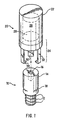
- FIG. 1 illustrates a temporary fiducial marker assembly which may be used in implementing an embodiment of the present invention.
- the temporary fiducial marker assembly illustrated in FIG. 1 includes a base 10 and an imaging marker 20.
- the base 10 has a threaded portion 12 at a first end.
- the threads 12 enable a surgeon to securely attach the base 10 into the skull or other desired portion of bone tissue of a patient.
- Other connecting structure is provided to securely and releasibly link the imaging marker 20 with the base 10.
- the end of the base 10 opposite the threaded portion 12 terminates in a socket head 14 which contains a socket-like recess 16. (It is anticipated that the base would be implanted into bone with the aid of an insertion tool that twists the base into the bone or into a hole provided in the bone.
- the recess is non-circular so as to better transmit the torque provided by such an insertion tool.
- a plurality of grooves 18 i.e. , three grooves around the circumference of the base portion 10.
- the socket 14 and the grooves 18 provide for the secure and releasable attachment of the imaging marker portion 20 with base portion 10.
- the imaging marker portion 20 of the temporary fiducial marker assembly may consist of two principal portions, a cylinder 22 and a cap 24.
- the cylinder 22 contains a cavity 26 (shown by dotted lines in FIG. 1) for receiving a mixture of imaging agents whose composition is determined by the imaging modalities to be employed. While in this version, the vessel containing the imaging agents is preferably cylindrical to simplify the process by which the centroid of the corresponding volume of imaging agent is determined, other shapes (such as a box or sphere) could be employed as well.
- the cylinder 22 is closed at one end and open at the other end to allow for the introduction of the imaging agents. In one version of the device, a cap 24 is used to seal off the open end of the cylinder 22 once the imaging agents have been added to the cylinder.
- the cap may be cemented or welded into place.
- the cap may be provided with a plug portion 28 that protrudes into and thereby helps seal off the cavity 26 of the cylinder 22 against leakage of the imaging agents.
- Other conventional filling and sealing techniques such as blow-molding, ultrasonic welding, or heat sealing, may be used.
- a cap may be provided with a protruding boss 30 and a plurality (e.g. , three) of snap arms 32, which terminate with inwardly projecting portions 34.
- the shape and dimensions of the boss 30 are in direct correspondence with the shape and size of the socket 16 provided in the base 10 to properly and securely center the imaging marker on the base.
- the snap arms 32 cooperate with the grooves 12 of the base 10 to detachably secure the imaging marker onto the base. While this example shows the use of snap arms, other fastener structures may be provided for attaching the marker to the base (e.g. , screw threads, clasps, hooks, etc.).
- the dimensions of the temporary fiducial marker assembly will be somewhat dependent on the state of the art of imaging. The greater the sensitivity of the scanner employed, the lesser the quantity of imaging material necessary to provide a suitable image, which in turn makes it possible to reduce the corresponding size of the marker that must be employed to contain the imaging material.
- the fiducial marker assembly including a base portion approximately 12mm in length and 2mm-3mm in diameter is sufficiently large to provide for the secure placement of the base into the bone beneath the skin. When the clinician prepares the patient for imaging, the base portion is exposed and an imaging marker approximately 6mm in length is attached to the base; the marker itself may protrude from the scalp and be exposed to air while a scan is performed on the patient.
- the base and the imaging marker housing are constructed of a bio-compatible organic polymer, such as polyether imide.
- fiducial marker which may be used in implementing the present invention
- the present invention is not limited to such a fiducial marker.
- the fiducial marker used in implementing the present invention need not necessarily be a cylindrical fiducial marker.
- Any fiducial marker may be used in implementing the present invention which is imageable in an image space produced by a scanner such as, for example, a magnetic resonance (MR) or computer tomography (CT) scanner.
- MR magnetic resonance
- CT computer tomography
- a three-dimensional internal coordinate system must be set up which is fixed within a human anatomy.
- the internal coordinate system is established within the anatomy by fixing three or more fiducial implants (i.e. , fiducial markers) to portions of the anatomy.
- the fiducial markers are fixed to points which will not change their spacial relationship to one another over a relatively long period of time, such as a few months or more.
- fiducial implants 40a, 40b and 40c are implanted in three separate, spaced locations within the skull 42 of a patient.
- a plane is formed which contains these fiducial markers 40a, 40b and 40c. Once a plane is defined, a three-dimensional coordinate system is defined. Any point within the body will be within the internal coordinate system.
- fiducial implants any three points that are affixed with respect to the region of interest can comprise the three points used to define the internal coordinate system.
- fiducial implants 40a, 40b and 40c that are identifiable and measurable by different imaging systems, such as CT imagers and MR imagers are preferred.
- the fiducial markers 40a, 40b and 40c may be relatively small and unobtrusive so that no discomfort or self consciousness will be experienced by the patient even though the patient may carry the implants for a relatively long period of time.
- a number M of markers are attached to the patient's head before images of the head are acquired (M is equal to 3 in FIG. 2A and FIG. 2B).
- the markers are left in place during the imaging and are not removed until after the completion of the surgical procedure that follows the imaging.
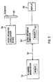
- FIG. 3 illustrates an imaging system which may be used in implementing an embodiment of the present invention. Additional details of such an imaging system are included in U.S. Patent Application Serial No. 08/162,986 filed on December 8, 1993 (abandoned, continuation application filed under Serial No. 08/459,549, issued as US Patent No.5,730,130).
- the images are loaded into the memory of a computer 52 illustrated in FIG. 3, which is referred to as the "planning workstation” and a method is executed by the planning workstation computer 52 to find the position of each of the markers within each of the images.
- the term "planning workstation” relates to the fact that the computer 52 provides additional programs that the surgeon may use to plan the surgical approach to be used on the patient. Because the volume image is three dimensional, the specification of a position requires three coordinates, typically referred to as x, y, and z. At this point, the method of the present invention is implemented to provide image space localization of the markers in the image space.
- the marker positions which we call the "positions in image space” or "image space positions" are transferred from the planning workstation 52 to a computer 54 located in the operating room, which is referred to as the "intra-operative computer".
- This transfer of the marker positions may be accomplished by means of a diskette, optical disk or tape, etc. which is written by the planning workstation and read by the intra-operative computer, or by means of a network connection 56 between the planning workstation and the intra-operative computer.
- N volume images are acquired, there will be M x N positions transferred from the planning workstation 52 to the intra-operative computer 54, one for each marker and each volume image, or 3 x M x N coordinates, since three coordinates are required for each position.
- some or all of the N volume images of the patient may be transferred from the planning workstation 52 to the intra-operative computer 54.
- the physical positions of the markers are measured. These physical positions are referred to as the "positions in physical space” or “physical space positions”.
- the measurement of a physical position is referred to as "physical space localization”.
- Physical space localization is accomplished with a precision instrument such as an "intra-operative localization device” (or ILD) 58 that is connected to the intra-operative computer 54.
- ILD 58 employs a hand-held wand (or pointer) 60 with which the surgeon touches each marker.
- the ILD is able to determine the position of the tip of the pointer 60 at any time.
- the surgeon When the surgeon has positioned the wand 60 so that it is touching a marker, the surgeon presses a button that causes the intra-operative computer 54 to write that position into its memory 62.
- the process of measuring the physical positions of the markers is completed by touching each of the M markers with the wand 60 and recording its position in the memory 62 of the intra-operative computer 54.
- each of the markers may be established, for example, by providing a divot (not illustrated) formed in the top of the cylinder 12 of the imaging marker portion 10 of the fiducial marker assembly.
- the tip of the pointer 60 of the ILD 58 may then be accommodated within the divot so that an exact position of the marker is established.
- two or more separate sets of coordinates are stored in the intra-operative computer: one set of 3 x M physical space coordinates and N sets of 3 x M image space coordinates, where M is the number of markers and N is the number of images stored in the planning workstation computer 52.
- Two sets of coordinates will almost never be the same, because the orientation of the head relative to the image scanners will almost always differ from each other and from the ILD.
- a computer implemented method can be used to determine how to transform the head image including the one set of image space coordinates so that it is aligned with the physical orientation of the head.
- it is possible to align any of the N images with any other of the N images by comparing the two sets of image space coordinates in the two images to determine how to transform one head image so that it is aligned with the other head image.
- registration The determination of the transformation necessary for alignment is referred to as "registration".
- another computer implemented method can be used to calculate the position in image space of the ILD, no matter where the ILD is located in physical space. If, for example, the surgeon places the tip of the ILD somewhere within the brain, the image space coordinates of that physical location in the brain can be determined. Once the position of a point in image space is known, the intra-operative computer 54 can determine the slice of the volume image in which that point lies. The slice may then be displayed on a monitor 64 that is visible to the surgeon. Additionally, a cursor may be placed on that slice in the image displayed on the monitor at the position of the ILD.
- the effect is that the surgeon sees the image position on the monitor that corresponds to the physical position of the pointer of the ILD.
- This process of determining the ILD position in image space and displaying the correct slice with the correctly positioned cursor can be done so quickly (ten or more times per second) that the surgeon perceives the cursor on the image displayed on the monitor as moving through image space as the ILD pointer 60 moves through physical space in the operating room.
- the result of the overall sequence of processes including image space localization, physical space localization, registration, transformation, and display is a navigation system that enhances the surgeon's ability to perform surgery by allowing a display of a physical position in image space on a real-time basis.
- the method according to the present invention may be implemented independently on each volume image.
- the method might first be applied to the CT image to determine the 3 x M image space coordinates for the M markers in that image. Then, the method would be applied to one of the MR images to determine the 3 x M image space coordinates for that image. Finally, the method would be applied to the second MR image to determine 3 x M coordinates for that image.
- Each of these three processes would be performed independently.
- the order in which the images are processed is not critical in practicing the present invention. The method according to the present invention will be described below as being applied to one volume image.
- a volume image consists of a set (typically 15 to 100) of rectangular arrays of integers. Each integer represents the intensity of the object averaged over a small three-dimensional rectangle called a "voxel.” All voxels within a volume image preferably have the same size and shape, an image slice consisting of one rectangular array of voxels.
- the rectangular array is typically a 128 by 128, 256 by 256, or 512 by 512 square, but other dimensions are possible.
- each integer is mapped into a brightness level from black through gray to white which appears on a tiny, square, called a "pixel" on a computer display screen. The effect of viewing the complete two dimensional array of pixels is that one cross sectional slice is seen on the computer display screen 64.
- the volume is thus viewed on the display screen one slice at a time.
- the x and y coordinates may be used to specify positions within a slice, while the z coordinate may be used to measure positions in a direction perpendicular to the slice.
- the method according to the present invention finds markers whose images are of a higher intensity than their surroundings. It is also tailored to find markers of a given size and shape. All of the marker may be visible in the image, or it may consist of both imageable and non-imageable parts. In one version the imageable part is a liquid, and the liquid is contained in a non-imageable container. It is the imageable part that is localized by the method according to the present invention, and the size and shape of this imageable part is important to the method. Henceforth, the term "marker” or "fiducial marker” refers to only the imageable portion of the fiducial marker assembly.
- Three pieces of geometrical information specify the size and shape of the marker adequately for the purposes of the present invention: (1) the radius of the largest sphere that can be inscribed within the marker, (2) the longest length of the marker ( i.e. , the greatest straight-line distance between any pair of points on the marker), and (3) the volume V m of the marker.
- a cylindrical marker as illustrated in FIG. 1 provides a useful example of these values, with the diameter of the circular face of the cylinder having a value d and its height having a value h.
- the radius of the largest inscribable sphere equals the smaller of d/2 or h/2
- the longest length of the marker is d 2 + h 2
- the volume V m is ⁇ d 2 h/4.
- Similar values can easily be determined for markers of different geometrical shapes or sizes other than cylindrical fiducial markers, such as, for example, spherical or cubic fiducial markers.
- the method illustrated in FIG. 4 finds "candidate voxels". Each candidate voxel lies within a bright region that might be the image of a marker. Minimal requirements are imposed by the method of FIG. 4 with the result that there are typically many more than M candidate points identified. If for example, M is four, the method of FIG. 4 might identify 100 candidates.
- the method of FIG. 5 selects from the candidates identified in the FIG. 4 method M candidate points that are most likely to lie within actual markers and determines a centroid for each marker.
- the method of FIG. 4 is designed so that it is unlikely to miss a true marker and the method of FIG. 5 is designed so that it is unlikely to accept a false marker.
- the first portion of the method receives the following as inputs:
- the first part of the method produces as an output a set of candidate voxels in response to the inputs.
- the second portion of the method receives the following as inputs:
- the second part of the method produces as an output a list of M "fiducial points.”
- Each fiducial point is a three dimensional position consisting of three coordinates x f , y f , z f , that are likely to be the centroid of a marker.
- the list is ordered with the first member of the list being most likely to be a marker centroid and the last being the least likely.
- the method illustrated in FIG. 4 operates on the entire volume image.
- step 102 of the method of FIG. 4 if the image is an MR image, a two dimensional, three-by-three median filter is applied within each slice.
- a set of nine voxels in that slice is considered.
- the set of nine voxels includes the voxel under consideration and its "eight-connected neighbors".
- the eight-connected neighbors of a voxel under consideration lie in the same slice as the voxel and consist, for example, of the four voxels that each share a common side with the voxel and the four voxels that share only a common corner with the voxel.
- the intensities of these nine voxels are ranked.
- the intensity that ranks fifth of these nine voxels is considered the median intensity of the set of nine voxels.
- a new image provided as a result of the filtering includes a voxel at the position of the voxel under consideration which is assigned an intensity equal to the median intensity. This process is described, for example, at pages 191 and 192 of Digital Image Processing by Rafael C. Gonzalez and Richard E. Woods, Addison-Wesley Publishing Co., New York, 1992.
- step 104 a new smaller image is formed by subsampling.
- Subsampling produces a new image by, for example, the following procedure:
- An intensity threshold is determined in step 106.
- the threshold preferably has a value that maximizes the between-group variance.
- the between-group variance is defined at, for example, page 22 of Computer and Robot Vision, Volume I, by Robert M. Haralick and Linda G. Shapiro, Addison-Wesley Publishing Co., New York, 1992.
- q 1 (t) is defined as the fraction of voxels that are classified as background and q 2 (t) is defined as the fraction of voxels that are classified as foreground
- u is defined as the mean intensity of the entire image
- u 1 (t) is defined as the mean intensity of the background voxels
- u 2 (t) is defined as the mean intensity of the foreground voxels
- the between-group variance is defined as: q 1 (t) [u 1 (t) - u] 2 + q 2 (t) [u 2 (t) - u] 2
- the threshold is preferably computed as the mean of two independently determined thresholds. The first of these independent thresholds is the threshold that maximizes the between-group variance. The second is the threshold that minimizes the Kullback information value.
- the Kullback information value is defined at, for example, page 25 of Computer and Robot Vision, Volume I, by Haralick and Shapiro.
- v 1 (t) is defined as the variance of the intensities of the background voxels and v 2 (t) is defined as the variance of the intensities of the foreground voxels
- the Kullback information value is defined as: (1 + log(2 ⁇ ))/2 - q 1 (t) log(q 1 (t)) - q 2 (t) log(q 2 (t)) + [q 1 (t) log(v 1 (t)) + q 2 (t) log(v 2 (t))]/2
- q 1 (t), q 2 (t), v 1 (t), and v 2 (t) are functions of the threshold value t, it is possible to vary the Kullback information value by varying the threshold value t.
- a binary image of foreground and background voxels is produced in step 108 based on the threshold determined in step 106.
- a voxel is a foreground voxel if its intensity is greater than or equal to the threshold intensity. Otherwise it is a background voxel.
- Foreground voxels are typically voxels that are part of the image of the patient's head and the markers.
- spurious detail tends to appear in the binary image produced by the previous step 108.
- the spurious detail is composed of apparent holes in the head caused by regions that produce a weak signal, such as in the areas of cerebrospinal fluid, the skull and sinuses.
- these holes in the binary image are filled in step 110.
- each slice is considered individually.
- a foreground component is a two-dimensionally connected set of foreground voxels. The holes are background regions completely enclosed within a slice by a single foreground component.
- These holes are found by identifying all sets of two-dimensionally connected background voxels that are not connected two-dimensionally to a background voxel in their slice that lies at one of the four corners of the image. Each such set is defined to be a hole that should be filled. The filling is accomplished by setting the voxels in each such set to a foreground voxel value.
- Two successive binary, two-dimensional, morphological operations are performed on each slice in step 112.
- the operations taken together have the effect of removing small components and small protrusions on large components.
- the operations are designed to be most likely to remove components and protrusions whose cross sections are smaller than or equal to the largest cross section of a marker.
- the operations are opening and dilation in that order.
- the structuring element is a square.
- the number of voxels on a side of the element is determined as follows: First the largest length of the marker is divided by v x . Then, that number is rounded up to the nearest integer. The resulting integer is the desired number of voxels on a side of the opening element.
- the dilation the element is a single voxel.
- Morphological operations are nonlinear operations on binary images that cause changes in the shape of the foreground objects. These operations are discussed in Chapters 1 and 2 of An Introduction to Morphological Image Processing by Edward R. Dougherty, SPIE Optical Engineering Press, Bellingham, Washington, 1992.
- the new shape of an object is determined by the manner in which a "structuring element" of a given shape fits within the object.
- the basic fundamental morphological operation is erosion.
- the determination of the new image involves the following two steps: First, the structuring element is placed successively at all possible positions within the image. The position of the center pixel of the element is noted whenever the entire element lies within the foreground. Second, a new image is generated in which each noted position is set to foreground. All other position are set to background.
- Dilation can be defined in terms of erosion. It consists of the following steps: First, the image is complemented, meaning that foreground voxels are set to background and background voxels are set to foreground. Second, the structuring element is rotated 180 degrees (this step has no effect on a square element). Third, erosion is effected. Fourth, the resulting image is complemented.
- opening Another morphological operation mentioned above is called opening. It consists of an erosion, followed by a dilation, each performed with the same structuring element.
- step 114 For each slice the binary image that was input to the previous step 112 and the binary image that was output by the previous step 112 are compared in step 114.
- a new binary image slice is produced in step 116 in which those voxels that were foreground voxels in the input image and were background voxels in the output image are set to the foreground value. The remaining voxels are set to a background value.
- the result is a binary image consisting only of the small components and protrusions that were removed in the previous step 112.
- the foreground is partitioned into three-dimensionally connected components in step 118 for the entire volume image.
- the definition of connectedness can be varied. It is noted that including the eight two-dimensionally eight-connected neighbors within the slice plus the two voxels at the same x and y positions on the neighboring slices works well for both CT and MR images.
- step 120 components in the image that are sufficiently similar in volume to a marker are selected.
- the component is selected as a possible marker component if and only if the volume V c of the component falls within a range [aV m , bV m ], where the values of a and b depend on the characteristics of the imager (e.g., a CT or MR imager) and V m is the marker volume.
- the intensity-weighted centroid of each selected component is found in step 122.
- the sums are taken over all voxels in the component.
- the voxels which contain the points x c , y c , z c are identified in step 124.
- the voxels identified in step 124 are the candidate voxels provided by the method of FIG. 4.
- the second part of the present invention is illustrated in FIG. 5 and operates on a small region of the original image around each candidate voxel.
- the method of FIG. 5 takes the steps described below for each candidate voxel identified in the method of FIG. 4.
- Step 152 of FIG. 5 generates a sphere centered on the candidate voxel having a radius R equivalent to the largest length of a marker being localized.
- R d 2 + h 2 .
- Step 154 determines whether a suitable threshold exists for the candidate. This determination can be made by checking each intensity value in the available range of intensities. Alternatively, a more efficient search strategy can be adopted such as a binary search strategy. In either case a suitable threshold is defined as follows: for a given threshold the set of foreground voxels that are three-dimensionally connected to the candidate voxel are identified. The threshold is suitable if the size and shape of this foreground component is sufficiently similar to that of a marker. There are two rules that determine whether the size and shape of the foreground component are sufficiently similar:
- S(t) is defined as the set of voxels in this region whose intensity i is greater than the threshold t and which are connected recursively (in 3D) to the starting point
- V(t) is defined as the volume of the set of voxels S(t)
- V h is the maximum volume
- V l is the minimum volume that are allowed for a marker image.
- step 154 determines that no such threshold exists, the candidate point is discarded in step 156. If there are two or more suitable thresholds,the smallest one is chosen as the threshold value.
- step 152 The voxel that contains the centroid x f , y f , z f is eventually fed back to step 152 as a candidate marker. If this second centroid differs from the first, it is fed back to step 152 and a third centroid is produced. This is accomplished as follows. If a determination is made in step 162 that the same centroid has not been produced twice in succession by the iteration, step 164 determines whether or not this is the third iteration for this candidate voxel. If the third iteration has occurred for the candidate voxel, the candidate is discarded in step 166. Otherwise the final centroid and its associated average intensity is recorded in step 168. The steps of FIG. 5 are then repeated for each of the other candidate voxels identified by the method illustrated in FIG. 4.
- FIG. 6 is a flowchart illustrating an embodiment of the localization method according to the present invention.
- Candidate voxels which may be included in candidate fiducial markers are determined in step 172, which may be performed according to the steps illustrated in FIG. 4.
- a region around each of the candidate voxels may be examined in step 174 to determine which of the candidate voxels identified in step 172 most likely correspond to the fiducial markers to be localized.
- Step 174 may be accomplished, for example, by performing the method illustrated in FIG. 5 for each of the candidate voxels determined in step 172.
- the centroids x f , y f , z f of the most likely candidate voxels determined in step 174 are ranked in step 176 according to the average intensity of their components.
- step 178 the M points with the highest intensities are declared to be fiducial points, which are output in order by rank. A candidate with a higher intensity is considered to be a more likely fiducial point.
- the M most likely candidates are declared as the fiducial points, where M is the number of fiducial markers being localized. However, a different number of most likely candidates may be declared in step 178.
Landscapes
- Engineering & Computer Science (AREA)
- Health & Medical Sciences (AREA)
- Physics & Mathematics (AREA)
- Life Sciences & Earth Sciences (AREA)
- Medical Informatics (AREA)
- General Physics & Mathematics (AREA)
- Theoretical Computer Science (AREA)
- Surgery (AREA)
- Nuclear Medicine, Radiotherapy & Molecular Imaging (AREA)
- General Health & Medical Sciences (AREA)
- Public Health (AREA)
- Veterinary Medicine (AREA)
- Heart & Thoracic Surgery (AREA)
- Molecular Biology (AREA)
- Computer Vision & Pattern Recognition (AREA)
- Animal Behavior & Ethology (AREA)
- Pathology (AREA)
- Biomedical Technology (AREA)
- High Energy & Nuclear Physics (AREA)
- Radiology & Medical Imaging (AREA)
- Optics & Photonics (AREA)
- Biophysics (AREA)
- Multimedia (AREA)
- Oral & Maxillofacial Surgery (AREA)
- Condensed Matter Physics & Semiconductors (AREA)
- Geometry (AREA)
- Quality & Reliability (AREA)
- Magnetic Resonance Imaging Apparatus (AREA)
- Apparatus For Radiation Diagnosis (AREA)
Claims (31)
- Un procédé permettant de localiser automatiquement des voxels de repères de clichés candidats dans un volume d'image, les repères de clichés candidats ayant une taille prédéterminée, le procédé comprenant l'étape de formation d'une image binaire de composants d'arrière-plan et d'avant-plan se basant sur ledit volume d'image ;
le procédé étant caractérisé par les étapes de :ouverture morphologique des composants d'avant-plan de l'image binaire en utilisant un élément légèrement plus grand que la taille prédéterminée et dilatation morphologique des composants d'avant-plan en utilisant un élément comprenant un seul voxel ; etlocalisation d'un centroïde d'un composant de l'image binaire sur lequel la dite étape d'ouverture et de dilatation morphologiques a été exécutée. - Le procédé de la revendication 1, comprenant en outre une étape de :revue du centroïde localisé, en examinant un volume sphérique centré sur le centroïde qui se trouve dans un rayon R égal à la plus grande dimension d'un repère de cliché représentatif.
- Le procédé de la revendication 1, comprenant en outre une étape de :revue du centroïde localisé, en examinant un volume sphérique centré sur ce centroïde qui se trouve dans un rayon R égal à la racine carrée de la somme des carrés de la hauteur et du diamètre d'un repère de cliché cylindrique représentatif.
- Le procédé de la revendication 2, comprenant en outre une étape de :établissement d'un seuil de luminosité t dépendant de la géométrie du repère de cliché employé.
- Le procédé de la revendication 4, comprenant en outre les étapes de :recherche du plus petit seuil de luminosité t tel qu'aucun voxel dont l'intensité est supérieure au seuil de luminosité t ne se trouve éloigné de plus de R du point d'intérêt, et élimination du point d'intérêt si la somme des volumes de ces voxels est inférieure à un premier paramètre.
- Le procédé de la revendication 5, comprenant en outre une étape d'augmentation du seuil de luminosité t jusqu'à ce que le volume V des voxels soit inférieur ou égal à un second paramètre.
- Le procédé de la revendication 6, comprenant en outre une étape de localisation d'un centre des voxels de repères de clichés candidats identifiés.
- Le procédé selon l'une quelconque des revendications 1 ou 4 à 7, dans lequel l'étape d'ouverture morphologique des composants d'avant-plan est exécutée pour éliminer les petits objets, tandis que l'étape de dilatation morphologique des composants d'avant-plan est sautée, et que l'étape de localisation est exécutée comme localisant un centroïde de chacun des petits objets éliminés.
- Le procédé de la revendication 8, comprenant en outre une étape de :revue du centroïde localisé correspondant aux petits objets, en examinant un volume sphérique centré sur le centroïde qui se trouve dans un rayon R égal à la plus grande dimension d'un repère de cliché représentatif.
- Le procédé de la revendication 8, comprenant en outre une étape de :revue du centroïde localisé correspondant aux petits objets, en examinant un volume sphérique centré sur ce centroïde qui se trouve dans un rayon R égal à la racine carrée de la somme des carrés de la longueur et du diamètre d'un repère de cliché cylindrique représentatif.
- Le procédé selon l'une quelconque des revendications 1 à 7, comprenant en outre les étapes de :détermination desquels parmi les voxels de repères de clichés candidats correspondent le plus probablement au repère de cliché à localiser ;classement des voxels de repères de clichés candidats les plus probables suivant une intensité moyenne de leurs composants ; etdéclaration des voxels de repères de clichés candidats les plus probables ordonnés ayant les intensités les plus élevées comme étant des points de cliché.
- Le procédé selon la revendication 11, dans lequel l'étape de détermination desquels parmi les voxels de repères de clichés candidats déterminés correspondent le plus probablement au repère de cliché à localiser comprend, pour chaque voxel de repère de cliché candidat déterminé, les étapes de :génération d'une sphère centrée sur le voxel de repère de cliché candidat déterminé, la sphère ayant un rayon équivalant à une longueur la plus grande d'un repère de cliché en cours de localisation ; détermination si, oui ou non, un seuil convenable existe pour le voxel de repère de cliché candidat déterminé ;élimination du voxel de repère de cliché candidat déterminé, si la valeur de seuil convenable n'existe pas ;détermination d'un composant tridimensionnel pondéré en intensité d'un composant d'avant-plan du voxel de repère de cliché candidat, si la valeur de seuil convenable existe effectivement ;calcul d'une intensité moyenne des voxels dans le composant d'avant-plan ;retour à l'étape de génération de la sphère, si un même centroïde n'est pas produit deux fois consécutivement et s'il ne s'agit pas d'une troisième itération pour un même voxel candidat ;élimination du voxel candidat, s'il s'agit d'une troisième itération pour le même voxel candidat ; et enregistrement du centroïde comme étant un centroïde final et enregistrement de son intensité moyenne calculée, si le même centroïde est produit deux fois consécutivement.
- Un procédé permettant de localiser automatiquement un nombre prédéterminé de repères de clichés dans au moins un volume d'image donné, comprenant les étapes de :recherche, dans ledit au moins volume d'image donné, des voxels qui peuvent se trouver dans des repères candidats et détermination des voxels candidats qui peuvent être inclus dans les voxels du dit au moins volume d'image donné correspondant à des repères de clichés ; etexamen d'une région dans ledit au moins volume d'image donné autour de chacun des voxels candidats ;et détermination desquels parmi les dits voxels candidats correspondent le plus probablement à une partie des dits repères de clichés dans ledit au moins volume d'image donné, les repères de clichés étant localisés selon le procédé de l'une des revendications 1 à 12.
- Le procédé de la revendication 13, dans lequel M = 4.
- Le procédé de la revendication 13, dans lequel la dite étape d'examen détermine lesquels M parmi les dits voxels candidats correspondent le plus probablement à une partie des dits repères de clichés dans ledit au moins volume d'image donné.
- Le procédé de la revendication 13, comprenant une étape de détermination d'un centroïde pour chacun des dits voxels candidats qui ont été déterminés correspondre le plus probablement à une partie des dits repères de clichés dans ledit au moins volume d'image donné.
- Le procédé de la revendication 16, comprenant en outre une étape de classement des centroïdes suivant une intensité moyenne de leurs composants.
- Le procédé de la revendication 13, dans lequel la dite étape de recherche, dans le volume d'image, des voxels qui se trouvent dans les repères candidats et détermination des voxels candidats qui peuvent être inclus dans des voxels du dit au moins volume d'image donné correspondant aux dits repères de clichés comprend les étapes de :application d'un filtre médian dans chacune parmi plusieurs tranches du dit au moins volume d'image donné ;formation d'un nouveau volume d'image plus petit pour chaque tranche, par sous-échantillonnage ;détermination d'une valeur de seuil d'intensité ;production d'une image binaire à partir de cette nouvelle image plus petite de voxels d'avant-plan et d'arrière-plan en réponse à la dite valeur de seuil d'intensité ;remplissage de tous les trous éventuels dans l'image binaire ;élimination de petits composants et de petites saillies sur de grands composants apparaissant dans l'image binaire ;sélection de composants dans l'image binaire éliminée qui sont les plus similaires à un repère de cliché, ledit nombre de composants étant supérieur au dit nombre prédéterminé M ; etfourniture des dits composants sélectionnés comme étant les voxels candidats.
- Le procédé de la revendication 18, dans lequel la dite étape d'application d'un filtre médian n'est exécutée que si le volume d'image est un volume d'image par résonance magnétique.
- Le procédé de la revendication 18, dans lequel la dite étape de remplissage de tous les trous éventuels dans l'image binaire n'est exécutée que si le volume d'image est un volume d'image par résonance magnétique.
- Le procédé de la revendication 18, dans lequel la dite étape d'élimination des petits composants et des petites saillies sur de grands composants apparaissant dans l'image binaire comprend l'exécution d'opérations morphologiques sur l'image binaire.
- Le procédé de la revendication 18, dans lequel les dites opérations morphologiques comprennent au moins deux parmi ouverture morphologique, dilatation morphologique et érosion morphologique.
- Le procédé de la revendication 13, dans lequel la dite étape d'examen d'une région dans le volume d'image autour de chacun des voxels candidats et de détermination desquels parmi les dits voxels candidats correspondent le plus probablement à une partie des dits repères de cliché dans ledit volume d'image comprend, pour chacun des dits voxels candidats, les étapes de :détermination si, oui ou non, une taille et une forme d'un jeu de voxels d'avant-plan connectés au dit voxel candidat sont similaires à un composant d'avant-plan d'un repère,élimination du voxel candidat si la taille et la forme ne sont pas déterminées comme étant similaires ; détermination d'un centroïde du jeu de voxels d'avant-plan ;répétition des dites étapes de détermination jusqu'à ce qu'un même centroïde ait été déterminé deux fois consécutivement ;élimination du voxel candidat si les étapes de détermination sont mises en oeuvre un nombre prédéterminé de fois ; etsi un même centroïde a été déterminé deux fois consécutivement, enregistrement du dit même centroïde comme étant un centroïde final et enregistrement d'une intensité correspondante du dit centroïde final.
- Le procédé de la revendication 23, dans lequel ledit nombre prédéterminé de fois est trois.
- Le procédé de la revendication 23, comprenant en outre une étape de classement des centroïdes finals enregistrés pour chacun des dits voxels candidats suivant leurs intensités enregistrées correspondantes.
- Le procédé de la revendication 18, dans lequel la dite étape d'examen d'une région dans le volume d'image autour de chacun des voxels candidats et de détermination desquels parmi les dits voxels candidats correspondent le plus probablement à une partie des dits repères de cliché dans ledit volume d'image comprend, pour chacun des dits voxels candidats, les étapes de :détermination si, oui ou non, une taille et une forme d'un jeu de voxels d'avant-plan connectés au dit voxel candidat sont similaires à un composant d'avant-plan d'un repère ;élimination du voxel candidat si la taille et la forme ne sont pas déterminées comme étant similaires ; détermination d'un centroïde du jeu de voxels d'avant-plan ;répétition des dites étapes de détermination jusqu'à ce qu'un même centroïde ait été déterminé deux fois consécutivement ;élimination du voxel candidat si les étapes de détermination sont mises en oeuvre un nombre prédéterminé de fois ; etsi un même centroïde a été déterminé deux fois consécutivement, enregistrement du dit même centroïde comme étant un centroïde final et enregistrement d'une intensité correspondante du dit centroïde final.
- Le procédé de la revendication 26, dans lequel ledit nombre prédéterminé de fois est trois.
- Le procédé de la revendication 25, comprenant en outre une étape de classement des centroïdes finals enregistrés pour chacun des dits voxels candidats suivant leurs intensités enregistrées correspondantes.
- Le procédé de la revendication 13, dans lequel les dits repères de cliché sont implantés dans une partie de l'anatomie humaine.
- Le procédé de la revendication 29, dans lequel la dite partie de l'anatomie humaine est une tête humaine.
- Le procédé de la revendication 13, dans lequel ledit volume d'image comprend au moins un volume d'image tomographique et un volume d'image par résonance magnétique.
Applications Claiming Priority (5)
| Application Number | Priority Date | Filing Date | Title |
|---|---|---|---|
| US16493393A | 1993-12-10 | 1993-12-10 | |
| US164933 | 1993-12-10 | ||
| US19672594A | 1994-02-15 | 1994-02-15 | |
| US196725 | 1994-02-15 | ||
| PCT/US1994/014059 WO1995015729A1 (fr) | 1993-12-10 | 1994-12-08 | Technique automatique permettant de localiser des reperes de cliches a fixation externe dans des images en volume de la tete |
Publications (3)
| Publication Number | Publication Date |
|---|---|
| EP0732899A1 EP0732899A1 (fr) | 1996-09-25 |
| EP0732899A4 EP0732899A4 (fr) | 1997-12-29 |
| EP0732899B1 true EP0732899B1 (fr) | 2002-10-16 |
Family
ID=26860981
Family Applications (1)
| Application Number | Title | Priority Date | Filing Date |
|---|---|---|---|
| EP95904833A Expired - Lifetime EP0732899B1 (fr) | 1993-12-10 | 1994-12-08 | Technique automatique permettant de localiser des reperes de cliches a fixation externe dans des images en volume de la tete |
Country Status (4)
| Country | Link |
|---|---|
| EP (1) | EP0732899B1 (fr) |
| CA (1) | CA2177140A1 (fr) |
| DE (1) | DE69431566T2 (fr) |
| WO (1) | WO1995015729A1 (fr) |
Cited By (1)
| Publication number | Priority date | Publication date | Assignee | Title |
|---|---|---|---|---|
| EP2504689A4 (fr) * | 2009-11-25 | 2016-06-22 | Dental Imaging Technologies Corp | Procédé de suivi de repères radiographiques dans des images de projection ct en série |
Families Citing this family (12)
| Publication number | Priority date | Publication date | Assignee | Title |
|---|---|---|---|---|
| AU742207B2 (en) * | 1998-06-22 | 2001-12-20 | Ao Technology Ag | Fiducial matching by means of fiducial screws |
| DK1175592T3 (da) | 1999-05-03 | 2003-10-06 | Synthes Ag | Positionsregistreringsanordning med hjælpemidler til fastlæggelse af tyngdekraftvektorens retning |
| EP1925256A1 (fr) | 2006-11-24 | 2008-05-28 | BrainLAB AG | Procédé et dispositif destinés à l'enregistrement d'une structure anatomique à l'aide de marques |
| US9826942B2 (en) | 2009-11-25 | 2017-11-28 | Dental Imaging Technologies Corporation | Correcting and reconstructing x-ray images using patient motion vectors extracted from marker positions in x-ray images |
| US9498182B2 (en) | 2012-05-22 | 2016-11-22 | Covidien Lp | Systems and methods for planning and navigation |
| US9439622B2 (en) | 2012-05-22 | 2016-09-13 | Covidien Lp | Surgical navigation system |
| US8750568B2 (en) * | 2012-05-22 | 2014-06-10 | Covidien Lp | System and method for conformal ablation planning |
| US9439623B2 (en) | 2012-05-22 | 2016-09-13 | Covidien Lp | Surgical planning system and navigation system |
| US9439627B2 (en) | 2012-05-22 | 2016-09-13 | Covidien Lp | Planning system and navigation system for an ablation procedure |
| CN112566581B (zh) | 2018-08-10 | 2024-03-19 | 柯惠有限合伙公司 | 用于消融可视化的系统 |
| EP4037595A1 (fr) | 2019-10-06 | 2022-08-10 | Universität Bern | Système et procédé de calcul de transformations de système de coordonnées |
| CN116236278B (zh) * | 2023-05-08 | 2023-07-18 | 江苏省人民医院(南京医科大学第一附属医院) | 一种骨隧道建立系统 |
Family Cites Families (3)
| Publication number | Priority date | Publication date | Assignee | Title |
|---|---|---|---|---|
| US4948955A (en) * | 1988-12-22 | 1990-08-14 | The Boeing Company | Barcode location determination |
| US5205289A (en) * | 1988-12-23 | 1993-04-27 | Medical Instrumentation And Diagnostics Corporation | Three-dimensional computer graphics simulation and computerized numerical optimization for dose delivery and treatment planning |
| US5575794A (en) * | 1993-02-12 | 1996-11-19 | Walus; Richard L. | Tool for implanting a fiducial marker |
-
1994
- 1994-12-08 EP EP95904833A patent/EP0732899B1/fr not_active Expired - Lifetime
- 1994-12-08 WO PCT/US1994/014059 patent/WO1995015729A1/fr not_active Ceased
- 1994-12-08 CA CA002177140A patent/CA2177140A1/fr not_active Abandoned
- 1994-12-08 DE DE69431566T patent/DE69431566T2/de not_active Expired - Lifetime
Cited By (1)
| Publication number | Priority date | Publication date | Assignee | Title |
|---|---|---|---|---|
| EP2504689A4 (fr) * | 2009-11-25 | 2016-06-22 | Dental Imaging Technologies Corp | Procédé de suivi de repères radiographiques dans des images de projection ct en série |
Also Published As
| Publication number | Publication date |
|---|---|
| EP0732899A4 (fr) | 1997-12-29 |
| CA2177140A1 (fr) | 1995-06-15 |
| EP0732899A1 (fr) | 1996-09-25 |
| DE69431566T2 (de) | 2003-02-20 |
| DE69431566D1 (de) | 2002-11-21 |
| WO1995015729A1 (fr) | 1995-06-15 |
Similar Documents
| Publication | Publication Date | Title |
|---|---|---|
| US5769789A (en) | Automatic technique for localizing externally attached fiducial markers in volume images of the head | |
| Fitzpatrick et al. | Image registration | |
| Grimson et al. | An automatic registration method for frameless stereotaxy, image guided surgery, and enhanced reality visualization | |
| Wang et al. | An automatic technique for finding and localizing externally attached markers in CT and MR volume images of the head | |
| Brummer | Hough transform detection of the longitudinal fissure in tomographic head images | |
| US7006677B2 (en) | Semi-automatic segmentation algorithm for pet oncology images | |
| US5961454A (en) | Fusion of anatomical data sets into stereotactic coordinates | |
| Fitzpatrick et al. | Visual assessment of the accuracy of retrospective registration of MR and CT images of the brain | |
| EP0927403B1 (fr) | Procede et appareil de correlation d'un corps avec son image | |
| Van Herk et al. | Automatic three‐dimensional correlation of CT‐CT, CT‐MRI, and CT‐SPECT using chamfer matching | |
| Jiang et al. | New approach to 3-D registration of multimodality medical images by surface matching | |
| US7889895B2 (en) | Method and apparatus for identifying pathology in brain images | |
| West et al. | Comparison and evaluation of retrospective intermodality image registration techniques | |
| US7106891B2 (en) | System and method for determining convergence of image set registration | |
| EP0732899B1 (fr) | Technique automatique permettant de localiser des reperes de cliches a fixation externe dans des images en volume de la tete | |
| Hill et al. | Correcting scaling errors in tomographic images using a nine degree of freedom registration algorithm | |
| Chen et al. | Image analysis of PET data with the aid of CT and MR images | |
| Hemler et al. | Registration error quantification of a surface‐based multimodality image fusion system | |
| Zuk et al. | A comparison of manual and automatic methods for registering scans of the head | |
| Wang et al. | Automatic technique for localizing externally attached markers in MR and CT volume images of the head | |
| WO1993018470A1 (fr) | Identification de caracteristiques anatomiques a partir de donnees | |
| Hawkes et al. | Coregistration of structural and functional images | |
| Hillman et al. | A fuzzy logic approach to identifying brain structures in MRI using expert anatomic knowledge | |
| WO2017198518A1 (fr) | Dispositif de traitement de données d'image | |
| Kuhn | Aim project a2003: Computer vision in radiology (covira) |
Legal Events
| Date | Code | Title | Description |
|---|---|---|---|
| PUAI | Public reference made under article 153(3) epc to a published international application that has entered the european phase |
Free format text: ORIGINAL CODE: 0009012 |
|
| 17P | Request for examination filed |
Effective date: 19960607 |
|
| AK | Designated contracting states |
Kind code of ref document: A1 Designated state(s): DE FR GB IT SE |
|
| A4 | Supplementary search report drawn up and despatched |
Effective date: 19971107 |
|
| AK | Designated contracting states |
Kind code of ref document: A4 Designated state(s): DE FR GB IT SE |
|
| DA4 | Supplementary search report drawn up and despatched (deleted) | ||
| RAP1 | Party data changed (applicant data changed or rights of an application transferred) |
Owner name: ALLEN, GEORGE S. |
|
| RA4 | Supplementary search report drawn up and despatched (corrected) |
Effective date: 19980811 |
|
| 17Q | First examination report despatched |
Effective date: 20010109 |
|
| GRAG | Despatch of communication of intention to grant |
Free format text: ORIGINAL CODE: EPIDOS AGRA |
|
| GRAG | Despatch of communication of intention to grant |
Free format text: ORIGINAL CODE: EPIDOS AGRA |
|
| GRAH | Despatch of communication of intention to grant a patent |
Free format text: ORIGINAL CODE: EPIDOS IGRA |
|
| GRAH | Despatch of communication of intention to grant a patent |
Free format text: ORIGINAL CODE: EPIDOS IGRA |
|
| GRAA | (expected) grant |
Free format text: ORIGINAL CODE: 0009210 |
|
| AK | Designated contracting states |
Kind code of ref document: B1 Designated state(s): DE FR GB IT SE |
|
| REG | Reference to a national code |
Ref country code: GB Ref legal event code: FG4D |
|
| REF | Corresponds to: |
Ref document number: 69431566 Country of ref document: DE Date of ref document: 20021121 |
|
| ET | Fr: translation filed | ||
| PLBE | No opposition filed within time limit |
Free format text: ORIGINAL CODE: 0009261 |
|
| STAA | Information on the status of an ep patent application or granted ep patent |
Free format text: STATUS: NO OPPOSITION FILED WITHIN TIME LIMIT |
|
| 26N | No opposition filed |
Effective date: 20030717 |
|
| PGFP | Annual fee paid to national office [announced via postgrant information from national office to epo] |
Ref country code: GB Payment date: 20091229 Year of fee payment: 16 Ref country code: FR Payment date: 20100106 Year of fee payment: 16 |
|
| PGFP | Annual fee paid to national office [announced via postgrant information from national office to epo] |
Ref country code: IT Payment date: 20091230 Year of fee payment: 16 |
|
| PGFP | Annual fee paid to national office [announced via postgrant information from national office to epo] |
Ref country code: DE Payment date: 20091230 Year of fee payment: 16 |
|
| PGFP | Annual fee paid to national office [announced via postgrant information from national office to epo] |
Ref country code: SE Payment date: 20091230 Year of fee payment: 16 |
|
| GBPC | Gb: european patent ceased through non-payment of renewal fee |
Effective date: 20101208 |
|
| REG | Reference to a national code |
Ref country code: FR Ref legal event code: ST Effective date: 20110831 |
|
| REG | Reference to a national code |
Ref country code: SE Ref legal event code: EUG |
|
| PG25 | Lapsed in a contracting state [announced via postgrant information from national office to epo] |
Ref country code: SE Free format text: LAPSE BECAUSE OF NON-PAYMENT OF DUE FEES Effective date: 20101209 |
|
| PG25 | Lapsed in a contracting state [announced via postgrant information from national office to epo] |
Ref country code: FR Free format text: LAPSE BECAUSE OF NON-PAYMENT OF DUE FEES Effective date: 20110103 |
|
| REG | Reference to a national code |
Ref country code: DE Ref legal event code: R119 Ref document number: 69431566 Country of ref document: DE Effective date: 20110701 |
|
| PG25 | Lapsed in a contracting state [announced via postgrant information from national office to epo] |
Ref country code: DE Free format text: LAPSE BECAUSE OF NON-PAYMENT OF DUE FEES Effective date: 20110701 Ref country code: GB Free format text: LAPSE BECAUSE OF NON-PAYMENT OF DUE FEES Effective date: 20101208 |
|
| PG25 | Lapsed in a contracting state [announced via postgrant information from national office to epo] |
Ref country code: IT Free format text: LAPSE BECAUSE OF NON-PAYMENT OF DUE FEES Effective date: 20101208 |