EP0733092B1 - Verbesserte vorrichtung und verfahren zur zersetzung mittels eines metallschmelzbades - Google Patents
Verbesserte vorrichtung und verfahren zur zersetzung mittels eines metallschmelzbades Download PDFInfo
- Publication number
- EP0733092B1 EP0733092B1 EP95903138A EP95903138A EP0733092B1 EP 0733092 B1 EP0733092 B1 EP 0733092B1 EP 95903138 A EP95903138 A EP 95903138A EP 95903138 A EP95903138 A EP 95903138A EP 0733092 B1 EP0733092 B1 EP 0733092B1
- Authority
- EP
- European Patent Office
- Prior art keywords
- feed
- zone
- bath
- vessel
- carbon
- Prior art date
- Legal status (The legal status is an assumption and is not a legal conclusion. Google has not performed a legal analysis and makes no representation as to the accuracy of the status listed.)
- Expired - Lifetime
Links
- 229910052751 metal Inorganic materials 0.000 title claims abstract description 29
- 239000002184 metal Substances 0.000 title claims abstract description 29
- 238000000034 method Methods 0.000 title claims description 33
- 238000000354 decomposition reaction Methods 0.000 title description 3
- 239000001257 hydrogen Substances 0.000 claims abstract description 20
- 229910052739 hydrogen Inorganic materials 0.000 claims abstract description 20
- UFHFLCQGNIYNRP-UHFFFAOYSA-N Hydrogen Chemical compound [H][H] UFHFLCQGNIYNRP-UHFFFAOYSA-N 0.000 claims abstract description 18
- QVGXLLKOCUKJST-UHFFFAOYSA-N atomic oxygen Chemical compound [O] QVGXLLKOCUKJST-UHFFFAOYSA-N 0.000 claims abstract description 14
- 239000001301 oxygen Substances 0.000 claims abstract description 14
- 229910052760 oxygen Inorganic materials 0.000 claims abstract description 14
- 239000000463 material Substances 0.000 claims description 47
- 230000001590 oxidative effect Effects 0.000 claims description 31
- OKTJSMMVPCPJKN-UHFFFAOYSA-N Carbon Chemical compound [C] OKTJSMMVPCPJKN-UHFFFAOYSA-N 0.000 claims description 23
- 229910052799 carbon Inorganic materials 0.000 claims description 23
- 239000007788 liquid Substances 0.000 claims description 21
- 239000007789 gas Substances 0.000 claims description 15
- 239000002826 coolant Substances 0.000 claims description 10
- 229910002091 carbon monoxide Inorganic materials 0.000 claims description 9
- UGFAIRIUMAVXCW-UHFFFAOYSA-N Carbon monoxide Chemical compound [O+]#[C-] UGFAIRIUMAVXCW-UHFFFAOYSA-N 0.000 claims description 8
- XEEYBQQBJWHFJM-UHFFFAOYSA-N Iron Chemical compound [Fe] XEEYBQQBJWHFJM-UHFFFAOYSA-N 0.000 claims description 8
- 229930195733 hydrocarbon Natural products 0.000 claims description 7
- 150000002430 hydrocarbons Chemical class 0.000 claims description 7
- 238000004939 coking Methods 0.000 claims description 5
- 229910052742 iron Inorganic materials 0.000 claims description 4
- 238000002156 mixing Methods 0.000 claims description 4
- 239000004215 Carbon black (E152) Substances 0.000 claims description 3
- 238000001816 cooling Methods 0.000 claims description 3
- 150000002431 hydrogen Chemical class 0.000 claims description 2
- 238000004064 recycling Methods 0.000 claims 2
- 238000007599 discharging Methods 0.000 claims 1
- 239000012768 molten material Substances 0.000 claims 1
- 238000003786 synthesis reaction Methods 0.000 abstract description 9
- 230000015572 biosynthetic process Effects 0.000 abstract description 8
- 238000007254 oxidation reaction Methods 0.000 abstract description 5
- 238000006243 chemical reaction Methods 0.000 abstract description 4
- 230000003647 oxidation Effects 0.000 abstract description 4
- 239000011449 brick Substances 0.000 abstract description 2
- CURLTUGMZLYLDI-UHFFFAOYSA-N Carbon dioxide Chemical compound O=C=O CURLTUGMZLYLDI-UHFFFAOYSA-N 0.000 description 18
- OKKJLVBELUTLKV-UHFFFAOYSA-N Methanol Chemical compound OC OKKJLVBELUTLKV-UHFFFAOYSA-N 0.000 description 15
- 229910002092 carbon dioxide Inorganic materials 0.000 description 15
- YMWUJEATGCHHMB-UHFFFAOYSA-N Dichloromethane Chemical compound ClCCl YMWUJEATGCHHMB-UHFFFAOYSA-N 0.000 description 12
- VNWKTOKETHGBQD-UHFFFAOYSA-N methane Chemical compound C VNWKTOKETHGBQD-UHFFFAOYSA-N 0.000 description 11
- 239000000047 product Substances 0.000 description 9
- 239000000203 mixture Substances 0.000 description 6
- QTBSBXVTEAMEQO-UHFFFAOYSA-N Acetic acid Chemical compound CC(O)=O QTBSBXVTEAMEQO-UHFFFAOYSA-N 0.000 description 5
- 229910000831 Steel Inorganic materials 0.000 description 5
- 239000010959 steel Substances 0.000 description 5
- XKRFYHLGVUSROY-UHFFFAOYSA-N Argon Chemical compound [Ar] XKRFYHLGVUSROY-UHFFFAOYSA-N 0.000 description 4
- BZLVMXJERCGZMT-UHFFFAOYSA-N Methyl tert-butyl ether Chemical compound COC(C)(C)C BZLVMXJERCGZMT-UHFFFAOYSA-N 0.000 description 4
- 239000003245 coal Substances 0.000 description 4
- 239000010813 municipal solid waste Substances 0.000 description 4
- 239000002893 slag Substances 0.000 description 4
- WFDIJRYMOXRFFG-UHFFFAOYSA-N Acetic anhydride Chemical compound CC(=O)OC(C)=O WFDIJRYMOXRFFG-UHFFFAOYSA-N 0.000 description 3
- 239000001569 carbon dioxide Substances 0.000 description 3
- 238000013461 design Methods 0.000 description 3
- 239000000446 fuel Substances 0.000 description 3
- -1 hydrogen- Chemical class 0.000 description 3
- 238000004519 manufacturing process Methods 0.000 description 3
- 239000007800 oxidant agent Substances 0.000 description 3
- 239000011819 refractory material Substances 0.000 description 3
- IJGRMHOSHXDMSA-UHFFFAOYSA-N Atomic nitrogen Chemical compound N#N IJGRMHOSHXDMSA-UHFFFAOYSA-N 0.000 description 2
- 238000010744 Boudouard reaction Methods 0.000 description 2
- LFQSCWFLJHTTHZ-UHFFFAOYSA-N Ethanol Chemical compound CCO LFQSCWFLJHTTHZ-UHFFFAOYSA-N 0.000 description 2
- LYCAIKOWRPUZTN-UHFFFAOYSA-N Ethylene glycol Chemical compound OCCO LYCAIKOWRPUZTN-UHFFFAOYSA-N 0.000 description 2
- PXHVJJICTQNCMI-UHFFFAOYSA-N Nickel Chemical compound [Ni] PXHVJJICTQNCMI-UHFFFAOYSA-N 0.000 description 2
- ATUOYWHBWRKTHZ-UHFFFAOYSA-N Propane Chemical compound CCC ATUOYWHBWRKTHZ-UHFFFAOYSA-N 0.000 description 2
- NINIDFKCEFEMDL-UHFFFAOYSA-N Sulfur Chemical compound [S] NINIDFKCEFEMDL-UHFFFAOYSA-N 0.000 description 2
- PNEYBMLMFCGWSK-UHFFFAOYSA-N aluminium oxide Inorganic materials [O-2].[O-2].[O-2].[Al+3].[Al+3] PNEYBMLMFCGWSK-UHFFFAOYSA-N 0.000 description 2
- 229910052786 argon Inorganic materials 0.000 description 2
- 230000005587 bubbling Effects 0.000 description 2
- 239000000356 contaminant Substances 0.000 description 2
- 238000010586 diagram Methods 0.000 description 2
- 239000002283 diesel fuel Substances 0.000 description 2
- 239000012530 fluid Substances 0.000 description 2
- 239000003350 kerosene Substances 0.000 description 2
- 239000000395 magnesium oxide Substances 0.000 description 2
- CPLXHLVBOLITMK-UHFFFAOYSA-N magnesium oxide Inorganic materials [Mg]=O CPLXHLVBOLITMK-UHFFFAOYSA-N 0.000 description 2
- AXZKOIWUVFPNLO-UHFFFAOYSA-N magnesium;oxygen(2-) Chemical compound [O-2].[Mg+2] AXZKOIWUVFPNLO-UHFFFAOYSA-N 0.000 description 2
- 239000003921 oil Substances 0.000 description 2
- TWNQGVIAIRXVLR-UHFFFAOYSA-N oxo(oxoalumanyloxy)alumane Chemical compound O=[Al]O[Al]=O TWNQGVIAIRXVLR-UHFFFAOYSA-N 0.000 description 2
- 239000012071 phase Substances 0.000 description 2
- 239000003870 refractory metal Substances 0.000 description 2
- 239000002904 solvent Substances 0.000 description 2
- 239000007858 starting material Substances 0.000 description 2
- 238000009628 steelmaking Methods 0.000 description 2
- 229910052717 sulfur Inorganic materials 0.000 description 2
- 239000011593 sulfur Substances 0.000 description 2
- GUVRBAGPIYLISA-UHFFFAOYSA-N tantalum atom Chemical compound [Ta] GUVRBAGPIYLISA-UHFFFAOYSA-N 0.000 description 2
- 230000008016 vaporization Effects 0.000 description 2
- AOPDRZXCEAKHHW-UHFFFAOYSA-N 1-pentoxypentane Chemical compound CCCCCOCCCCC AOPDRZXCEAKHHW-UHFFFAOYSA-N 0.000 description 1
- 229910052582 BN Inorganic materials 0.000 description 1
- PZNSFCLAULLKQX-UHFFFAOYSA-N Boron nitride Chemical compound N#B PZNSFCLAULLKQX-UHFFFAOYSA-N 0.000 description 1
- UXVMQQNJUSDDNG-UHFFFAOYSA-L Calcium chloride Chemical compound [Cl-].[Cl-].[Ca+2] UXVMQQNJUSDDNG-UHFFFAOYSA-L 0.000 description 1
- ZAMOUSCENKQFHK-UHFFFAOYSA-N Chlorine atom Chemical compound [Cl] ZAMOUSCENKQFHK-UHFFFAOYSA-N 0.000 description 1
- VYZAMTAEIAYCRO-UHFFFAOYSA-N Chromium Chemical compound [Cr] VYZAMTAEIAYCRO-UHFFFAOYSA-N 0.000 description 1
- RYGMFSIKBFXOCR-UHFFFAOYSA-N Copper Chemical compound [Cu] RYGMFSIKBFXOCR-UHFFFAOYSA-N 0.000 description 1
- 229910052581 Si3N4 Inorganic materials 0.000 description 1
- 229910001362 Ta alloys Inorganic materials 0.000 description 1
- XTXRWKRVRITETP-UHFFFAOYSA-N Vinyl acetate Chemical compound CC(=O)OC=C XTXRWKRVRITETP-UHFFFAOYSA-N 0.000 description 1
- HCHKCACWOHOZIP-UHFFFAOYSA-N Zinc Chemical compound [Zn] HCHKCACWOHOZIP-UHFFFAOYSA-N 0.000 description 1
- 238000010521 absorption reaction Methods 0.000 description 1
- 239000002253 acid Substances 0.000 description 1
- 150000007513 acids Chemical class 0.000 description 1
- 150000001252 acrylic acid derivatives Chemical class 0.000 description 1
- 150000001336 alkenes Chemical class 0.000 description 1
- 238000013459 approach Methods 0.000 description 1
- 125000003118 aryl group Chemical group 0.000 description 1
- 239000006227 byproduct Substances 0.000 description 1
- 239000001110 calcium chloride Substances 0.000 description 1
- 229910001628 calcium chloride Inorganic materials 0.000 description 1
- AXCZMVOFGPJBDE-UHFFFAOYSA-L calcium dihydroxide Chemical compound [OH-].[OH-].[Ca+2] AXCZMVOFGPJBDE-UHFFFAOYSA-L 0.000 description 1
- 239000000920 calcium hydroxide Substances 0.000 description 1
- 229910001861 calcium hydroxide Inorganic materials 0.000 description 1
- 235000011116 calcium hydroxide Nutrition 0.000 description 1
- 238000001311 chemical methods and process Methods 0.000 description 1
- 239000007795 chemical reaction product Substances 0.000 description 1
- 239000000460 chlorine Substances 0.000 description 1
- 229910052801 chlorine Inorganic materials 0.000 description 1
- 229910052804 chromium Inorganic materials 0.000 description 1
- 239000011651 chromium Substances 0.000 description 1
- 239000000571 coke Substances 0.000 description 1
- 238000004891 communication Methods 0.000 description 1
- 150000001875 compounds Chemical class 0.000 description 1
- 230000006835 compression Effects 0.000 description 1
- 238000007906 compression Methods 0.000 description 1
- 238000010276 construction Methods 0.000 description 1
- 229910052802 copper Inorganic materials 0.000 description 1
- 239000010949 copper Substances 0.000 description 1
- 230000001419 dependent effect Effects 0.000 description 1
- 230000009429 distress Effects 0.000 description 1
- 238000009826 distribution Methods 0.000 description 1
- 230000002708 enhancing effect Effects 0.000 description 1
- 239000000284 extract Substances 0.000 description 1
- 239000000835 fiber Substances 0.000 description 1
- 239000010794 food waste Substances 0.000 description 1
- 239000002737 fuel gas Substances 0.000 description 1
- 239000003502 gasoline Substances 0.000 description 1
- 230000005484 gravity Effects 0.000 description 1
- 238000011905 homologation Methods 0.000 description 1
- WGCNASOHLSPBMP-UHFFFAOYSA-N hydroxyacetaldehyde Natural products OCC=O WGCNASOHLSPBMP-UHFFFAOYSA-N 0.000 description 1
- 238000009413 insulation Methods 0.000 description 1
- 239000012774 insulation material Substances 0.000 description 1
- 229910001338 liquidmetal Inorganic materials 0.000 description 1
- WPBNNNQJVZRUHP-UHFFFAOYSA-L manganese(2+);methyl n-[[2-(methoxycarbonylcarbamothioylamino)phenyl]carbamothioyl]carbamate;n-[2-(sulfidocarbothioylamino)ethyl]carbamodithioate Chemical compound [Mn+2].[S-]C(=S)NCCNC([S-])=S.COC(=O)NC(=S)NC1=CC=CC=C1NC(=S)NC(=O)OC WPBNNNQJVZRUHP-UHFFFAOYSA-L 0.000 description 1
- 239000000155 melt Substances 0.000 description 1
- 238000002844 melting Methods 0.000 description 1
- 238000012986 modification Methods 0.000 description 1
- 239000003345 natural gas Substances 0.000 description 1
- 229910052759 nickel Inorganic materials 0.000 description 1
- 229910052757 nitrogen Inorganic materials 0.000 description 1
- 230000003287 optical effect Effects 0.000 description 1
- 235000013348 organic food Nutrition 0.000 description 1
- 239000010893 paper waste Substances 0.000 description 1
- 239000003208 petroleum Substances 0.000 description 1
- 239000003209 petroleum derivative Substances 0.000 description 1
- 239000000843 powder Substances 0.000 description 1
- 239000001294 propane Substances 0.000 description 1
- 230000005855 radiation Effects 0.000 description 1
- 239000000376 reactant Substances 0.000 description 1
- 239000011214 refractory ceramic Substances 0.000 description 1
- HQVNEWCFYHHQES-UHFFFAOYSA-N silicon nitride Chemical compound N12[Si]34N5[Si]62N3[Si]51N64 HQVNEWCFYHHQES-UHFFFAOYSA-N 0.000 description 1
- 238000004513 sizing Methods 0.000 description 1
- 239000002002 slurry Substances 0.000 description 1
- 229910052566 spinel group Inorganic materials 0.000 description 1
- 238000004544 sputter deposition Methods 0.000 description 1
- 229910000601 superalloy Inorganic materials 0.000 description 1
- 229910052715 tantalum Inorganic materials 0.000 description 1
- 231100000331 toxic Toxicity 0.000 description 1
- 230000002588 toxic effect Effects 0.000 description 1
- WFKWXMTUELFFGS-UHFFFAOYSA-N tungsten Chemical compound [W] WFKWXMTUELFFGS-UHFFFAOYSA-N 0.000 description 1
- 229910052721 tungsten Inorganic materials 0.000 description 1
- 239000010937 tungsten Substances 0.000 description 1
- 238000009834 vaporization Methods 0.000 description 1
- XLYOFNOQVPJJNP-UHFFFAOYSA-N water Substances O XLYOFNOQVPJJNP-UHFFFAOYSA-N 0.000 description 1
- 239000001993 wax Substances 0.000 description 1
- 229910052725 zinc Inorganic materials 0.000 description 1
- 239000011701 zinc Substances 0.000 description 1
Images


Classifications
-
- C—CHEMISTRY; METALLURGY
- C10—PETROLEUM, GAS OR COKE INDUSTRIES; TECHNICAL GASES CONTAINING CARBON MONOXIDE; FUELS; LUBRICANTS; PEAT
- C10J—PRODUCTION OF PRODUCER GAS, WATER-GAS, SYNTHESIS GAS FROM SOLID CARBONACEOUS MATERIAL, OR MIXTURES CONTAINING THESE GASES; CARBURETTING AIR OR OTHER GASES
- C10J3/00—Production of combustible gases containing carbon monoxide from solid carbonaceous fuels
- C10J3/57—Gasification using molten salts or metals
-
- C—CHEMISTRY; METALLURGY
- C10—PETROLEUM, GAS OR COKE INDUSTRIES; TECHNICAL GASES CONTAINING CARBON MONOXIDE; FUELS; LUBRICANTS; PEAT
- C10K—PURIFYING OR MODIFYING THE CHEMICAL COMPOSITION OF COMBUSTIBLE GASES CONTAINING CARBON MONOXIDE
- C10K3/00—Modifying the chemical composition of combustible gases containing carbon monoxide to produce an improved fuel, e.g. one of different calorific value, which may be free from carbon monoxide
- C10K3/02—Modifying the chemical composition of combustible gases containing carbon monoxide to produce an improved fuel, e.g. one of different calorific value, which may be free from carbon monoxide by catalytic treatment
- C10K3/04—Modifying the chemical composition of combustible gases containing carbon monoxide to produce an improved fuel, e.g. one of different calorific value, which may be free from carbon monoxide by catalytic treatment reducing the carbon monoxide content, e.g. water-gas shift [WGS]
-
- B—PERFORMING OPERATIONS; TRANSPORTING
- B01—PHYSICAL OR CHEMICAL PROCESSES OR APPARATUS IN GENERAL
- B01J—CHEMICAL OR PHYSICAL PROCESSES, e.g. CATALYSIS OR COLLOID CHEMISTRY; THEIR RELEVANT APPARATUS
- B01J2219/00—Chemical, physical or physico-chemical processes in general; Their relevant apparatus
- B01J2219/18—Details relating to the spatial orientation of the reactor
- B01J2219/182—Details relating to the spatial orientation of the reactor horizontal
-
- C—CHEMISTRY; METALLURGY
- C10—PETROLEUM, GAS OR COKE INDUSTRIES; TECHNICAL GASES CONTAINING CARBON MONOXIDE; FUELS; LUBRICANTS; PEAT
- C10J—PRODUCTION OF PRODUCER GAS, WATER-GAS, SYNTHESIS GAS FROM SOLID CARBONACEOUS MATERIAL, OR MIXTURES CONTAINING THESE GASES; CARBURETTING AIR OR OTHER GASES
- C10J2200/00—Details of gasification apparatus
- C10J2200/09—Mechanical details of gasifiers not otherwise provided for, e.g. sealing means
-
- C—CHEMISTRY; METALLURGY
- C10—PETROLEUM, GAS OR COKE INDUSTRIES; TECHNICAL GASES CONTAINING CARBON MONOXIDE; FUELS; LUBRICANTS; PEAT
- C10J—PRODUCTION OF PRODUCER GAS, WATER-GAS, SYNTHESIS GAS FROM SOLID CARBONACEOUS MATERIAL, OR MIXTURES CONTAINING THESE GASES; CARBURETTING AIR OR OTHER GASES
- C10J2200/00—Details of gasification apparatus
- C10J2200/15—Details of feeding means
- C10J2200/152—Nozzles or lances for introducing gas, liquids or suspensions
-
- C—CHEMISTRY; METALLURGY
- C10—PETROLEUM, GAS OR COKE INDUSTRIES; TECHNICAL GASES CONTAINING CARBON MONOXIDE; FUELS; LUBRICANTS; PEAT
- C10J—PRODUCTION OF PRODUCER GAS, WATER-GAS, SYNTHESIS GAS FROM SOLID CARBONACEOUS MATERIAL, OR MIXTURES CONTAINING THESE GASES; CARBURETTING AIR OR OTHER GASES
- C10J2300/00—Details of gasification processes
- C10J2300/09—Details of the feed, e.g. feeding of spent catalyst, inert gas or halogens
- C10J2300/0953—Gasifying agents
- C10J2300/0959—Oxygen
-
- C—CHEMISTRY; METALLURGY
- C10—PETROLEUM, GAS OR COKE INDUSTRIES; TECHNICAL GASES CONTAINING CARBON MONOXIDE; FUELS; LUBRICANTS; PEAT
- C10J—PRODUCTION OF PRODUCER GAS, WATER-GAS, SYNTHESIS GAS FROM SOLID CARBONACEOUS MATERIAL, OR MIXTURES CONTAINING THESE GASES; CARBURETTING AIR OR OTHER GASES
- C10J2300/00—Details of gasification processes
- C10J2300/16—Integration of gasification processes with another plant or parts within the plant
- C10J2300/164—Integration of gasification processes with another plant or parts within the plant with conversion of synthesis gas
- C10J2300/1656—Conversion of synthesis gas to chemicals
- C10J2300/1659—Conversion of synthesis gas to chemicals to liquid hydrocarbons
-
- Y—GENERAL TAGGING OF NEW TECHNOLOGICAL DEVELOPMENTS; GENERAL TAGGING OF CROSS-SECTIONAL TECHNOLOGIES SPANNING OVER SEVERAL SECTIONS OF THE IPC; TECHNICAL SUBJECTS COVERED BY FORMER USPC CROSS-REFERENCE ART COLLECTIONS [XRACs] AND DIGESTS
- Y02—TECHNOLOGIES OR APPLICATIONS FOR MITIGATION OR ADAPTATION AGAINST CLIMATE CHANGE
- Y02P—CLIMATE CHANGE MITIGATION TECHNOLOGIES IN THE PRODUCTION OR PROCESSING OF GOODS
- Y02P20/00—Technologies relating to chemical industry
- Y02P20/141—Feedstock
- Y02P20/143—Feedstock the feedstock being recycled material, e.g. plastics
Definitions
- the present invention relates to the general field of molten baths for the disassociation of material containing carbon, and preferably hydrogen as well.
- a mass of carbonaceous fuel e.g., coal
- a high temperature liquid e.g., molten iron
- WO 92/01492 to Nagel teaches two immiscible zones (layers) of different molten metal temperatures.
- Tyrer U.S. 1,803,221 teaches production of hydrogen from methane in a two-zone unit, but provides no means for flow by convection between the two zones and does not suggest the baffle separators used in the apparatus of the present invention.
- Axelsson U.S. 4,511,372 does his whole process in a single vessel at high pressure, primarily to suppress dust.
- the lance of the present invention can be distinguished from the conventional tuyeres commonly used in steel making, in that the tuyeres are submerged beneath the molten steel and do not pass through any substantial portion of the molten steel. Further, the tuyeres are generally used for introducing oxygen, argon, and other gases, whereas the present lances are particularly used for introducing feed materials which contain hydrocarbons which can cause substantial coking. Therefore, it is a particular objective of the present invention to substantially reduce the amount of coking formed within the conduit or lance of the invention. This reduces the plugging difficulty which is often encountered with lances operating at these high temperatures, particularly when the lances are injecting liquids comprising hydrocarbons.
- a vessel having top and bottom walls a feed zone and an oxidizing zone and containing a molten bath to levels 116, 118 respectively for the decomposition of carbon- (and preferably hydrogen-) containing materials is improved by providing upwardly extending submerged baffle means 114 above the bottom wall abutting the feed zone and defining one wall of a recycle zone (chimney) 108 communicating between liquid in the oxidizing zone and in the feed zone.
- the apparatus also comprises horizontal extending baffle means 115 above the bottom wall.
- the horizontally extending submerged baffle means 115 is integral with a lower portion of the downwardly extending baffle means 114 and arranged so as to define the lower end of a generally L-shaped recycle zone 108 , much as a hearth is arranged beneath a chimney.
- the apparatus further comprises vapor zone separator or baffle means 112 ; the vapor zone separator means separates the vapor space above the liquid baths so that the vapor space of the feed zone is separated from the vapor space of the oxidizing zone.
- This vapor zone separator means 112 abuts the oxidizing zone and extends downward into the liquid of the oxidizing zone to define the other wall of said chimney of the recycle zone 108 , but not sufficiently far so as to contact the horizontal extending baffle means 115 .
- the vessel includes a top wall 100A and a bottom wall 100B and is preferably lined with brick or castable refractories and may be pre-stressed to maintain the refractories in compression even when the vessel is pressurized and hot.
- Downwardly extending baffle means 114 and horizontal extending baffle means 115 can be made of refractory materials or even of tungsten, tantalum, or other high-melting refractory metal which may be coated with refractory ceramics.
- Vapor zone separator means 112 will preferably be of the same material as downwardly extending baffle means 114 , and will preferably be hermetically attached to the top wall of closed vessel 100 .
- Oxidizer feed means 107 can be any suitable tuyere design, well-known in the steel-making industry.
- Feed inlet 105 can operate by gravity or pump (high pressure pump if the vessel operates under pressure).
- the preferred CO and H 2 products are useful for the conventional Fischer-Tropsch synthesis taught e.g., in Chemical Process Industries by R. Norris Schreve, McGraw-Hill, 1967, p. 775.
- iron is most preferred for specialized applications
- copper, zinc, especially chromium, manganese, or nickel, or other meltable metal in which carbon is somewhat soluble, may be used alone or in mixture.
- Natural gas (CH 4 ), liquified petroleum gas (LPG), propane, petroleum naphtha, light or heavy distillate, vacuum and other resids, solvent de-asphalted pitch (SDA), aromatic extracts, FCC slurry oil; trash garbage, tires, coal and virtually any other hydrocarbon-containing material.
- LPG liquified petroleum gas
- SDA solvent de-asphalted pitch
- aromatic extracts FCC slurry oil
- trash garbage tires, coal and virtually any other hydrocarbon-containing material.
- Products are CO, CO 2 , H 2 plus sulfur and other contaminants in feed which may be outputted in slag which can be periodically drained off.
- sulfur is preferably outputted as gas in the hydrogen stream and is then treated conventionally by the Claus process and the SCOT (Shell Claus Offgas Treatment) unit.
- Temperature is preferably 1,150° to 1,600°, more preferably 1,250° to 1,500°, and most preferably 1,300° to 1,450°C in the feed zone, and usually preferably 50° to 150°C higher in the oxidation zone.
- the present invention is useful for the production of a wide variety of end-products, including all those which can be produced by the well-known Fischer-Tropsch process, e.g., naphthas, diesel fuel, jet fuel (kerosene), as particularly commercialized by Sasol in South Africa.
- the Mobil Oil "M-Gas" process (U.S. 3,998,899, etc.) may be employed.
- the invention will be particularly valuable for the flexible production of reformulated fuels as mandated or as desirable for protection of the environment, e.g., methanol, methyl tertbutyl ether (MTBE) and tert amyl ether (TAME), etc.
- the invention functions entirely from distress or low-valued hydrocarbons, air (for oxidation), and water (to supply hydrogen and additional oxygen). It is particularly noteworthy that the invention can utilize the exothermic carbon oxidation reaction so that it can function without need for external energy input. Additionally, the endothermic Boudouard reaction (CO 2 + C ⁇ 2CO) can be used to control temperature within the two reaction zones, and particularly to control the differentials so as to adjust convection circulation of materials between the zones as desired.
- Syngas uses, per Kirk-Othmer, CO/H 2 without any other reactants as building blocks, e.g., glycol synthesis, modified Fischer-Tropsch syntheses to olefins or waxes, and acetic acid synthesis; those involving
- CO/H 2 and employed to make additional use of compounds derived from synthesis gas, e.g., homologation of methanol to ethanol; those that use a deravative based on CO/H 2 , e.g., methanol, as a starting material for a further reaction sequence, e.g., Mobil's MTG (methanol to gasoline) process or the vinyl acetate process; and energy-efficient processes, e.g., those that make syngas for use in combined-cycle plants; and those that use the carbon monoxide for subsequent syntheses, e.g., of acetic anhydride, acrylates, Koch acids, etc.
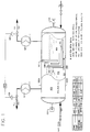
- Figure 1 is a schematic diagram of a section view of the closed vessel 100 showing the feed zone 104 and the oxidizing zone 106 separated by the chimney/hearth-like recycle zone 108 defined by downwardly extending baffle means 114 /horizontal extending baffle means 115 and vapor zone separator means 112 , along with the vessel 100 .
- Figure 1 shows the other elements suitable for operation in combination with the lance of the invention, but does not show the lance itself.
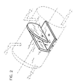
- Figure 2 is a detail of Figure 1 showing the baffles 135 and 136.
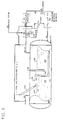
- Figure 3 is a schematic diagram showing the optional water-gas shift reactor 60 , Fisher-Tropsch reactor 64, the optional Boudouard reactor 80 which occurs in the molten bath oxidizing zone 106 , and the removal of carbon dioxide by means of the Benfield or Pressure Swing Absorption processes.
- Figure 3 shows schematically the other elements suitable for working in conjunction with the lance of the present invention, but does not show the lance itself.
- Figure 4 shows a preferred lance, with the lance in place as element 205 impinging on the surface of the liquid so as to depress it and actually pierce it, forming bubbles.
- Figure 5 is a schematic of a more preferred lance.
- Figure 5A is a cross sectional area at section AA of the lance
- Figure 5B is a cross-sectional detail of the lance tip.
- Figure 6 is a schematic of a slanted lance which may be above the molten surface or can preferably extend into the molten bath.
- the main vessel (a refractory-lined steel vessel 100 ) encloses and partially defines feed zone 104 , oxidizing zone 106 , lower circulation zone 113 , and L-shaped recycle zone 108 .
- Feed zone 104 receives feed through feed inlet 105 .
- Oxygen enters through oxidizer feed means 107 into oxidizing zone 106 .
- Oxidizing zone 106 and recycle zone 108 are controlled by pressure control means 120 which acts on control valve 128 and control valve 129 to throttle H2 outlet 130 and CO outlet 132 differentially as desired.
- Cooler 127 and cooler 126 protect control valve 128 and control valve 129 by cooling the products.
- Level controllers 133 and level controller 134 control the level in the feed and in the oxidizing zone, respectively, and feed signals to pressure control means 120 to maintain those levels.
- the feed 105 will preferably be directed downwardly with sufficient force to pierce the surface (or penetrate through a portion of the depth) of the molten metal bath 104, more preferably with sufficient force to cause bubbling and mixing of the feed with the liquid metal bath, and most preferably will extend below the molten surface.
- Figure 4 shows a preferred lance and shows the lance in place as element 205 impinging on the surface of the liquid so as to depress it and actually pierce it, forming bubbles.
- Figure 5 is a schematic of a more preferred lance.
- Figure 5A is a cross sectional area at section AA of the lance
- Figure 6B is a cross-sectional detail of the lance tip.
- FIG. 2 is a detail of the baffles.
- Baffle 135 and baffle 136 are shown in more detail in Figure 2.
- baffle 135 has both a horizontal and a vertical projection
- baffle 136 is primarily vertical in its projection and is sealed hermetically to the edges of refractory-lined steel vessel 100 to effectively separate the gas spaces above the feed zone and the oxidizing zone.
- baffle 135 and baffle 136 define lower circulation zone 113 , recycle zone 108 , and additionally separate the two gas phases as mentioned above.
- the recycle zone 108 is particularly formed by a hearth-like substantially horizontal projection of baffle 135 and the vertical projection of baffle 135 acts with baffle 136 to form a chimney-like vertical section to the recycle zone 108.
- This configuration is an important feature of the apparatus because it provides the necessary circulation which moves the carbon first through lower circulation zone 113 from the feed zone to the oxidizing zone 106 after feed zone 104, thence through recycle zone 108 after the carbon has been largely removed in the oxidizing zone closed vessel 100.
- the apparatus of Figure 1 has a temperature of approximately 1300°C in feed zone 104 , 1400°C in oxidizing zone 106 , and emits hydrogen and CO at approximately those temperatures, respectively.
- Pressure within closed vessel 100 is preferably from 0 to 50 bars, more preferably from 0.1 to 40 bars, and most preferably from 1 to 25 bars above atmospheric, though higher pressures, even as high as 100 bars can be utilized with special construction if desired for special circumstances.
- the feed will generally be fed from a source at ambient temperature, or in any case at much lower temperature than the temperature of the molten bath. Generally, keeping the feed material as cool as possible as it approaches the high temperature of the bath will be desirable to avoid coking within the feed lance. This will generally be accomplished by maintaining a velocity within the conduit in the range of from about 1-10 meters per second, and sizing the conduit so the residence time of said feed material in said conduit is from about 0.1-10 seconds. In general, this will keep the temperature in the conduit through which the feed material is flowing below about 315°C (about 600°F), more preferably below about 200°C (below about 400°F).
- Feed zone 104 preferably contains about 0 to 4.3%, more preferably about 1 to 4%, and most preferably 3% carbon.
- the carbon content in oxidizing zone 106 is an amount less than in feed zone 104 determined by the circulation rate of the molten metal and the feed rate of carbon to the feed zone.
- the vessel is a conventional refractory-lined design of steel suitable for the temperature and other surface conditions.
- the oxygen source is preferably 99.9% oxygen distilled from an oxygen plant operating on air (not shown) but may be air where the additional nitrogen is tolerable.
- lance 205 is shown entering through the upper portion of vessel 100 and is directed downwardly toward, or preferably extending below the liquid surface of molten bath 104, ending in communication with nozzle 206 which forms a jet 210 of fluid directed downwardly toward the surface of molten bath 100 so as to depress the surface.
- Preferred embodiments would be feed materials flowing through conduit 205 will have sufficient velocity to actually penetrate below the surface of bath 104 to a depth of 3-100 cm (1-36 inches) below the nozzle tip and cause bubbling, and to reduce coke formation in the conduit.
- the conduit 205 is jacketed with a jacket 212, preferably coaxially (concentric) with the conduit 205. Still more preferably, the conduit (lance) 205 can be surrounded by insulation shown in Figure 5A as surrounding the jacket to reduce quantities of coolant required to maintain the temperature in the conduit below a minimum temperature to avoid decomposition and/or vaporization in the conduit.
- Preferred insulation materials are magnesium oxide or aluminum oxide (alumina) powder or fibers, spinels (mixtures of magnesium oxide and aluminum oxide); preferred materials for the conduit itself are refractory metals, e.g. tantalum, and superalloys such as InconelTM 625; and preferred materials for the jacket are silicon nitride, alumina, and boron nitride; preferred coolant materials to flow through the annular space 215 include argon, steam, and methane.
- preferred materials for the conduit itself are refractory metals, e.g. tantalum, and superalloys such as InconelTM 625
- preferred materials for the jacket are silicon nitride, alumina, and boron nitride
- preferred coolant materials to flow through the annular space 215 include argon, steam, and methane.
- the coolant material itself is ejected axially around the feed material being ejected from nozzle 206 through openings 218, so that the coolant substantially surrounds the feed material exiting from the nozzle and directed toward the surface of the molten bath.
- conduit need not be entirely vertical, it may be slanted or bent or curved so as to provide a horizontal component to the jet 210 impinging on (or below) the surface of the molten bath, as shown in Figure 6.
- This horizontal component can be valuable in enhancing the circulation of the molten metal from the oxidizing zone to the oxidizing zone by flowing under baffle 135.
- Figure 6 shows a slanted conduit and jacket assembly (similar to that shown in detail in Figures 5, 5A, and 5B), but slanted so as to direct some of its force in a horizontal direction and cause fluid from molten bath 104 to more quickly circulate under baffle 135 .
- the conduit can also be slanted toward one side of the molten bath so as to cause circulation along one wall of the molten bath, and the baffle 135 can provide a larger lower opening at the point struck by flow from the lance, to further enhance circulation.
- the feed material is liquid
- the process further comprises controlling the pressure drop across the nozzle to at least about 1370 K Pa (200psi), and maintaining the liquid velocity at about 50 meters (150 feet) per second.
- Further preferred embodiments comprise injecting the feed materials through a substantially downwardly directed conduit passing through a wall of the vessel containing the molten bath and communicating with a nozzle beneath the surface of the bath, and to cause mixing of the materials with the bath beneath the surface.
- the conduit can be insulated or cooled to reduce the increase in temperature of the feed materials so said feed materials flow through said conduit and said nozzle to reduce the coking of the hydrocarbon content of the feed materials.
- An optional preferred embodiment is to recycle a portion of carbon dioxide made by oxidizing a portion of the product CO to CO 2 , back to the metal bath by injecting at a point where the molten metal contains substantial quantities of dissolved carbon, so that the dissolved carbon reacts with the CO 2 to form approximately two moles of CO for each mole of CO 2 thereby cooling the bath.
- the feed rate is 22.3 tonnes/hour of SDA bottoms.
- the molten iron circulation is 9,000 tonnes/hour through recycle zone 108 and 1.75 tonnes/hour of hydrogen are emitted through H 2 outlet 130 and 43.8 tonnes/hour of CO are emitted through CO outlet 132 .
- the results for this and other Examples are shown in Table A.
- Example I The procedure of Example I is followed except that methane is added to the feed for heat balance.
- the ratio of hydrogen to carbon monoxide in the product gas is approximately 1:1 on a molar basis.
- Example I The procedure of Example I is followed, except that steam is added to the feed for heat balance.
- the ratio of hydrogen to carbon monoxide in the product gas is approximately 1:1 on a molar basis.
- Example I The procedures of Example I are followed except that the feed is coal and the approximate molar ratio of carbon monoxide to hydrogen is 3:1 and except that 20,000 Kg/hour (44,000 pounds/hour) of steam are injected through oxidizer feed means 107 along with 10,000 Kg/hour (22,500 pounds/hour) of oxygen.
- Example I The procedures of Example I are followed except that the feed is mixed non-metallic trash (largely waste paper) and garbage (largely organic food residue), which is dried by using heat from the process, and the molar ratio of carbon monoxide to hydrogen is approximately 1:1.
- Example II The procedure of Example I is followed except that the feed is methylene chloride, which has been contaminated and has no commercial value but represents a substantial disposal problem. Carbon monoxide and hydrogen are produced in a molar ratio of approximately 1:1.5. To neutralize the chlorine and avoid toxic emissions, .91Kg (2 pounds) of slaked lime CaO per pound of methylene chloride is added near the top surface of feed zone liquid level 116 and oxidizing zone liquid level 118 , and 1.14Kg (2.5 pounds) of slag per pound of methylene chloride is permitted to flow outward through an outlet (not shown) which skims the surface of feed zone liquid level 116 and oxidizing zone liquid level 118. The slag comprises largely CaCl 2 .
- Example I is continued and some of the carbon monoxide produced is mixed with steam 66 reacted to produce CO 2 + H 2 in water-gas shift reactor 60 .
- the carbon dioxide is separated from hydrogen in CO 2 removal closed vessel 102. This hydrogen and hydrogen from H 2 outlet 130 are mixed with the remaining CO.
- the syngas 62 is reacted in Fisher-Tropsch reactor 64 to produce Fisher-Tropsch liquids 68 .
- the Fischer-Tropsch liquids comprise naphtha, kerosene, and diesel fuel.
- the CO 2 by-product from water-gas shift reactor 60 is fed to zone 106 ; it reacts with carbon dissolved in the molten metal to form two moles of CO for each mole of CO 2 fed to zone 106.
- compositions, methods, or embodiments discussed are intended to be only illustrative of the invention disclosed by this specification. Variations of these compositions, methods, or embodiments are readily apparent to a person of skill in the art based upon the teachings of this specification and are therefore intended to be included as part of the inventions disclosed herein.
Landscapes
- Chemical & Material Sciences (AREA)
- Engineering & Computer Science (AREA)
- Combustion & Propulsion (AREA)
- Oil, Petroleum & Natural Gas (AREA)
- Organic Chemistry (AREA)
- Chemical Kinetics & Catalysis (AREA)
- General Chemical & Material Sciences (AREA)
- Manufacture And Refinement Of Metals (AREA)
- Treatment Of Steel In Its Molten State (AREA)
- Coating With Molten Metal (AREA)
- Processing Of Solid Wastes (AREA)
- Vertical, Hearth, Or Arc Furnaces (AREA)
- Waste-Gas Treatment And Other Accessory Devices For Furnaces (AREA)
Claims (11)
- Verfahren zur Zersetzung von kohlenstoff- und wasserstoffhaltigem Feedmaterial in einem Metallschmelzbad, das folgendes umfaßt: das Einspritzen des kohlenstoff- und wasserstoffhaltigen Feedmaterials durch eine Lanze in das Schmelzbad, das Lösen von Kohlenstoff in dem Metallbad, und das Einblasen von Sauerstoff unter Erzeugung eines Kohlenmonoxidstroms, der CO aus dem gelösten Kohlenstoff umfaßt; wobei der Schritt des Einspritzens des Feedmaterials in das Bad, das im wesentlichen abwärts gerichtete Einspritzen des Feedmaterials durch eine Lanze umfaßt, die ein unteres Ende aufweist, das sich in das Bad erstreckt, unter ausreichendem Druck, um die Vermischung des Feedmaterials in der Metallschmelze unterhalb der Badoberfläche zu bewirken, wobei das Feedmaterial durch eine Düse in der Lanze eingespritzt wird, die sich unterhalb der Badoberfläche befindet, wobei die Düse mit einer Leitung ausgestattet ist, die im wesentlichen ummantelt ist, und wobei das Verfahren des weiteren das Durchflößen eines Kühlmediums durch den Mantel umfaßt, so daß die Leitung im wesentlichen gekühlt wird und daß das darin fließende Material die Verkohlung jeglichen Kohlenwasserstoffgehalts des Feedmaterials innerhalb der Lanze verhindert.
- Verfahren gemäß Anspruch 1, wobei der Schritt des Durchflößens des Kühlmediums durch den Mantel ferner das Entladen des Kühlmediums aus dem Mantel umfaßt, so daß ein aus der Düse austretender Feedmaterialstrahl im wesentlichen umgeben wird.
- Verfahren nach Anspruch 1 oder 2, wobei der Schritt des Durchflößens des Kühlmediums das Steuern der Geschwindigkeit des Kühlmediums umfaßt, um die Überschreitung der Temperatur von 315°C (600°F) in dem vorzugsweise ringförmigen Mantel zu verhindern.
- Verfahren gemäß irgendeinem der obigen Ansprüche, das ferner den Schritt der Steuerung der Geschwindigkeit des aus der Düse austretenden Feedmaterials auf 30-300 Meter pro Sekunde (100-1000 Fuß pro Sekunde) umfaßt.
- Verfahren gemäß irgendeinem der obigen Ansprüche, wobei sich das Feedmaterial beim Austritt aus der Düse in der Gasphase befindet, und wobei das Verfahren ferner die Steuerung des aus der Düse austretenden Feedmaterials auf einen ausreichenden Wert umfaßt, so daß sich innerhalb des Schmelzbades Blasen des sich in der Gasphase befindlichen Feedmaterials ausbilden.
- Verfahren gemäß irgendeinem der obigen Ansprüche, wobei das Feedmaterial flüssig ist, und wobei das Verfahren ferner die Steuerung des Druckabfalls durch die Düse auf wenigstens 1370 kPa (200 psi) umfaßt.
- Verfahren gemäß irgendeinem der obigen Ansprüche, wobei das Metallschmelzbad Eisen umfaßt und wobei das Feedmaterial Kohlenwasserstoffe umfaßt.
- Verfahren gemäß irgendeinem der obigen Ansprüche, wobei die Lanze im wesentlichen abwärts ,gerichtet ist und durch eine Wandung eines Gefäßes tritt, das das Schmelzbad enthält.
- Verfahren nach Anspruch 1, das zusätzlich folgendes umfaßt: a) die Oxidation eines Anteils des CO zu CO2, und b) die Rückführung des CO2 zum Bad, indem wenigstens ein Anteil des CO2 zu einem Zeitpunkt in die Metallschmelze eingeblasen wird, zu dem die Metallschmelze wesentliche Mengen an gelöstem Kohlenstoff enthält, wobei der gelöste Kohlenstoff mit dem CO2 so reagiert, daß sich ungefähr 2 Mol CO für jedes Mol CO2 ausbilden, wobei die Temperatur des Bades gekühlt wird.
- Metallschmelzbadvorrichtung zur Zersetzung von kohlenstoff- und wasserstoffhaltigem Feed und zur Erzeugung von Wasserstoff, wobei die Vorrichtung folgendes umfaßt: ein gasundurchlässiges Gefäß mit einer oberen Wandung und einer unteren Wandung; ein Mittel zum Zuführen des kohlenstoff- und wasserstoffhaltigen Feeds zu dem Gefäß; ein Metallschmelzbad am Boden des Gefäßes, wobei das Metallschmelzbad von der oberen Wandung beabstanded ist; ein Mittel, einschließlich des Gefäßes, um eine Feedzone innerhalb des Gefäßes zur Aufnahme des Feeds und zur Lösung des Kohlenstoffs und eine Oxidationszone zur Aufnahme des sauerstoffhaltigen Materials innerhalb des Gefäßes auszubilden; eine Gasphase in jeder Zone oberhalb dem Pegel des Metallschmelzbades und zwischen dem Metallschmelzbad und der oberen Wandung des Gefäßes, wobei das die Feedzone und die Oxidationszone bildende Mittel folgendes umfaßt:a. ein erstes im Gefäß angebrachtes Prallblechmittel, das eine Gasphase aus der Feedzonevon einer Gasphase aus der Oxidationszone abtrennt, wobei sich das erste Prallblechmittel im wesentlichen gasdicht von der oberen Wandung des Gefäßes abwärts erstreckt und eine untere Kante aufweist, die in das Metallschmelzbad eindringt, sich jedoch nicht durch dieses hindurch erstreckt, so daß die Gasphasen der Feedzone und der Oxidationszone getrennt ausgebildet werden; "b. ein zweites im Gefäß angebrachtes Prallblechmittel, das von dem ersten Prallblechmittel beabstanded ist und sich innerhalb des Bades befindet, das einen abwärts gerichteten Fortsatz aufweist und eine obere Kante auf einem Pegel umfaßt, der höher als die untere Kante des ersten Prallblechmittels ist, das einen integralen horizontalen Fortsatz aufweist, der sich im wesentlichen horizontal von einem unteren Ende des abwärts gerichteten Fortsatzes erstreckt und eine solche Länge aufweist, daß er sich unterhalb und über die untere Kante des ersten Prallblechmittels hinaus erstreckt, wodurch der integrale horizontale Fortsatz zusammen mit der unteren Wandung des gasdichten Gefäßes eine untere Umwälzzone für das Schmelzbad von der Feedzone bis hin zur Oxidationszone bildet, wobei das erste Prallblechmittel und der abwärts gerichtete Fortsatz des zweiten Prallblechmittels teilweise die Feedzone und die Oxidationszone bildet, wobei der abwärts gerichtete Fortsatz und der integrale horizontale Fortsatz des zweiten Prallblechmittels und des ersten Prallblechmittels eine allgemein L-förmige Rückführungszone bilden, wodurch das Schmelzmaterial aus der Feedzone, das den Kohlenstoff aus dem Feed enthält, unter dem horizontalen Fortsatz des zweiten Prallblechmittels hindurch in die Oxidationszone hinein zirkulieren kann, und wobei Flüssigkeit aus der Oxidationszone, die nach Kontakt mit Sauerstoff an Kohlenstoff verarmt ist, über den horizontalen Fortsatz des zweiten Prallblechmittels unter der unteren Kante des ersten Prallblechmittels zurückzufließen und zwischen dem abwärtsgerichteten Fortsatz des zweiten Prallblechmittels und dem ersten Prallblechmittel und über die obere Kante des abwärts gerichteten Fortsatzes des zweiten Prallblechmittels, in einer fortwährenden Umwälzungsschleife in die Feedzone zurück aufzusteigen vermag; undc. wobei das Mittel zur Zuführung des kohlenstoff- und wasserstoffhaltigen Feeds zu dem Gefäß eine im wesentlichen abwärts gerichtete Lanze umfaßt, die eine Leitung aufweist, die durch einen oberen Teil des gasdichten Gefäßes, das das Schmelzbad enthält, hindurchtritt, wobei die Leitung mit einer Düse in Verbindung steht, die so angeordnet ist, daß ein Strahl des Feedmaterials in das Bad gelangt und die Vermischung des Feedmaterials mit dem Bad bewirkt, und wobei die Leitung Ummantelungsmittel umfaßt, durch die die Leitung mittels eines Kühlmittels gekühlt wird, das durch das Ummantelungsmittel fließt, um den Temperaturanstieg des Materials zu vermindern, wenn es durch die Leitung und die Düse zum Schmelzbad fließt.
- Vorrichtung nach Anspruch 10, die zusätzlich Mittel zur Steuerung der Geschwindigkeit des Feedmaterials, das die Leitung verläßt, auf 30-300 Meter pro Sekunde (100-1000 Fuß pro Sekunde) aufweist.
Applications Claiming Priority (3)
| Application Number | Priority Date | Filing Date | Title |
|---|---|---|---|
| US16346893A | 1993-12-07 | 1993-12-07 | |
| US163468 | 1993-12-07 | ||
| PCT/US1994/013421 WO1995016010A1 (en) | 1993-12-07 | 1994-11-16 | Improved molten metal decomposition apparatus and process |
Publications (2)
| Publication Number | Publication Date |
|---|---|
| EP0733092A1 EP0733092A1 (de) | 1996-09-25 |
| EP0733092B1 true EP0733092B1 (de) | 1997-08-06 |
Family
ID=22590143
Family Applications (1)
| Application Number | Title | Priority Date | Filing Date |
|---|---|---|---|
| EP95903138A Expired - Lifetime EP0733092B1 (de) | 1993-12-07 | 1994-11-16 | Verbesserte vorrichtung und verfahren zur zersetzung mittels eines metallschmelzbades |
Country Status (6)
| Country | Link |
|---|---|
| EP (1) | EP0733092B1 (de) |
| AT (1) | ATE156511T1 (de) |
| AU (1) | AU1211195A (de) |
| CA (1) | CA2176966C (de) |
| DE (1) | DE69404861T2 (de) |
| WO (1) | WO1995016010A1 (de) |
Families Citing this family (3)
| Publication number | Priority date | Publication date | Assignee | Title |
|---|---|---|---|---|
| EP0954511A1 (de) * | 1996-11-22 | 1999-11-10 | Ashland Inc. | Reaktor und verfahren mit geschmolzenem metall |
| HU227714B1 (en) | 2000-02-29 | 2012-01-30 | Mitsubishi Heavy Ind Ltd | Biomass gasifying furnace and system for methanol synthesis using gas produced by gasifying biomass |
| DE102005053526A1 (de) * | 2005-11-08 | 2007-05-10 | Müller, Horst | Vorrichtung zur Erzeugung von Brenngas |
Family Cites Families (6)
| Publication number | Priority date | Publication date | Assignee | Title |
|---|---|---|---|---|
| AU7299674A (en) * | 1973-09-12 | 1976-03-11 | Uss Eng & Consult | Gasification of coal |
| US4017271A (en) * | 1975-06-19 | 1977-04-12 | Rockwell International Corporation | Process for production of synthesis gas |
| JPS55149388A (en) * | 1979-05-10 | 1980-11-20 | Sumitomo Metal Ind Ltd | Gasification of solid carbonaceous substance by ion bath |
| DE3131293C2 (de) * | 1980-12-01 | 1987-04-23 | Sumitomo Metal Industries, Ltd., Osaka | Verfahren zur Vergasung von festem, teilchenförmigem, kohlenstoffhaltigem Brennstoff |
| DE3334687A1 (de) * | 1983-09-24 | 1985-04-18 | Klöckner-Humboldt-Deutz AG, 5000 Köln | Verfahren und vorrichtung zur herstellung eines aus wasserstoff und kohlenmonoxid bestehenden synthesegases |
| WO1994004633A1 (en) * | 1990-06-21 | 1994-03-03 | Ashland Oil, Inc. | Improved molten metal decomposition apparatus and process |
-
1994
- 1994-11-16 AT AT95903138T patent/ATE156511T1/de not_active IP Right Cessation
- 1994-11-16 WO PCT/US1994/013421 patent/WO1995016010A1/en not_active Ceased
- 1994-11-16 CA CA002176966A patent/CA2176966C/en not_active Expired - Fee Related
- 1994-11-16 DE DE69404861T patent/DE69404861T2/de not_active Expired - Fee Related
- 1994-11-16 AU AU12111/95A patent/AU1211195A/en not_active Abandoned
- 1994-11-16 EP EP95903138A patent/EP0733092B1/de not_active Expired - Lifetime
Also Published As
| Publication number | Publication date |
|---|---|
| CA2176966A1 (en) | 1995-06-15 |
| DE69404861T2 (de) | 1998-03-12 |
| ATE156511T1 (de) | 1997-08-15 |
| CA2176966C (en) | 2005-08-23 |
| WO1995016010A1 (en) | 1995-06-15 |
| EP0733092A1 (de) | 1996-09-25 |
| AU1211195A (en) | 1995-06-27 |
| DE69404861D1 (de) | 1997-09-11 |
Similar Documents
| Publication | Publication Date | Title |
|---|---|---|
| JP2660102B2 (ja) | 改良された溶融金属分解装置および方法 | |
| US8052946B2 (en) | System and process for upgrading heavy hydrocarbons | |
| US5435814A (en) | Molten metal decomposition apparatus | |
| US5645615A (en) | Molten decomposition apparatus and process | |
| JPS6197103A (ja) | 転化方法 | |
| JPH0676586B2 (ja) | 合成ガスの製法および合成ガス製造用装置 | |
| JPH0143799B2 (de) | ||
| US8430939B2 (en) | Radiant heat flux enhanced organic material gasification system | |
| CA1049792A (en) | Process and apparatus for producing molten iron | |
| CA1076360A (en) | Method and apparatus for continuous gasification, of solid and/or fluid carbon-containing and/or hydro-carbon-containing substances in molten iron in a reaction vessel | |
| CA2176966C (en) | Improved molten metal decomposition apparatus and process | |
| USRE42832E1 (en) | Method for reforming organics into shorter-chain unsaturated organic compounds | |
| CA2169345C (en) | Process for eliminating organic pollutant residues in synthesis gas obtained during refuse gasification | |
| US6432149B1 (en) | Burner-feed multi-zone molten metal syngas generator | |
| WO2012152772A1 (en) | Process and reactor for producing synthesis gas | |
| US2905544A (en) | Suspension process for the production of co and h2 from a solid carbonaceous fuel, oxygen and steam | |
| US20050074395A1 (en) | Process for the production of synthesis gas from heavy charges such as heavy crude oils and distillation residues by means of partial oxidation | |
| AU573440B2 (en) | Hydrocarbons pyrolysis | |
| SU386520A1 (ru) | ВСЕСОЮЗНА;* j ''Ш^^-^mm'^i^i^:.^ | |
| EP4482920A1 (de) | Festbettvergaser | |
| WO1998004654A1 (en) | Multi-zone molten-metal hydrogen generator | |
| HK1193627A (en) | Enhanced plasma gasifiers for producing syngas |
Legal Events
| Date | Code | Title | Description |
|---|---|---|---|
| PUAI | Public reference made under article 153(3) epc to a published international application that has entered the european phase |
Free format text: ORIGINAL CODE: 0009012 |
|
| 17P | Request for examination filed |
Effective date: 19960612 |
|
| AK | Designated contracting states |
Kind code of ref document: A1 Designated state(s): AT BE DE DK ES FR GB IT NL PT SE |
|
| GRAG | Despatch of communication of intention to grant |
Free format text: ORIGINAL CODE: EPIDOS AGRA |
|
| 17Q | First examination report despatched |
Effective date: 19961105 |
|
| GRAH | Despatch of communication of intention to grant a patent |
Free format text: ORIGINAL CODE: EPIDOS IGRA |
|
| GRAH | Despatch of communication of intention to grant a patent |
Free format text: ORIGINAL CODE: EPIDOS IGRA |
|
| GRAA | (expected) grant |
Free format text: ORIGINAL CODE: 0009210 |
|
| AK | Designated contracting states |
Kind code of ref document: B1 Designated state(s): AT BE DE DK ES FR GB IT NL PT SE |
|
| PG25 | Lapsed in a contracting state [announced via postgrant information from national office to epo] |
Ref country code: NL Free format text: LAPSE BECAUSE OF FAILURE TO SUBMIT A TRANSLATION OF THE DESCRIPTION OR TO PAY THE FEE WITHIN THE PRESCRIBED TIME-LIMIT Effective date: 19970806 Ref country code: IT Free format text: LAPSE BECAUSE OF FAILURE TO SUBMIT A TRANSLATION OF THE DESCRIPTION OR TO PAY THE FEE WITHIN THE PRESCRIBED TIME-LIMIT;WARNING: LAPSES OF ITALIAN PATENTS WITH EFFECTIVE DATE BEFORE 2007 MAY HAVE OCCURRED AT ANY TIME BEFORE 2007. THE CORRECT EFFECTIVE DATE MAY BE DIFFERENT FROM THE ONE RECORDED. Effective date: 19970806 Ref country code: FR Free format text: LAPSE BECAUSE OF FAILURE TO SUBMIT A TRANSLATION OF THE DESCRIPTION OR TO PAY THE FEE WITHIN THE PRESCRIBED TIME-LIMIT Effective date: 19970806 Ref country code: DK Free format text: LAPSE BECAUSE OF NON-PAYMENT OF DUE FEES Effective date: 19970806 Ref country code: BE Effective date: 19970806 Ref country code: AT Effective date: 19970806 |
|
| REF | Corresponds to: |
Ref document number: 156511 Country of ref document: AT Date of ref document: 19970815 Kind code of ref document: T |
|
| REF | Corresponds to: |
Ref document number: 69404861 Country of ref document: DE Date of ref document: 19970911 |
|
| PGFP | Annual fee paid to national office [announced via postgrant information from national office to epo] |
Ref country code: FR Payment date: 19971015 Year of fee payment: 4 |
|
| PGFP | Annual fee paid to national office [announced via postgrant information from national office to epo] |
Ref country code: BE Payment date: 19971020 Year of fee payment: 4 |
|
| PGFP | Annual fee paid to national office [announced via postgrant information from national office to epo] |
Ref country code: NL Payment date: 19971023 Year of fee payment: 5 |
|
| PGFP | Annual fee paid to national office [announced via postgrant information from national office to epo] |
Ref country code: SE Payment date: 19971024 Year of fee payment: 4 |
|
| PGFP | Annual fee paid to national office [announced via postgrant information from national office to epo] |
Ref country code: DK Payment date: 19971103 Year of fee payment: 4 |
|
| PG25 | Lapsed in a contracting state [announced via postgrant information from national office to epo] |
Ref country code: SE Effective date: 19971106 |
|
| PGFP | Annual fee paid to national office [announced via postgrant information from national office to epo] |
Ref country code: ES Payment date: 19971112 Year of fee payment: 4 |
|
| PG25 | Lapsed in a contracting state [announced via postgrant information from national office to epo] |
Ref country code: PT Effective date: 19971113 |
|
| EN | Fr: translation not filed | ||
| NLV1 | Nl: lapsed or annulled due to failure to fulfill the requirements of art. 29p and 29m of the patents act | ||
| PG25 | Lapsed in a contracting state [announced via postgrant information from national office to epo] |
Ref country code: ES Free format text: LAPSE BECAUSE OF FAILURE TO SUBMIT A TRANSLATION OF THE DESCRIPTION OR TO PAY THE FEE WITHIN THE PRESCRIBED TIME-LIMIT Effective date: 19980223 |
|
| PLBE | No opposition filed within time limit |
Free format text: ORIGINAL CODE: 0009261 |
|
| STAA | Information on the status of an ep patent application or granted ep patent |
Free format text: STATUS: NO OPPOSITION FILED WITHIN TIME LIMIT |
|
| 26N | No opposition filed | ||
| REG | Reference to a national code |
Ref country code: GB Ref legal event code: IF02 |
|
| PGFP | Annual fee paid to national office [announced via postgrant information from national office to epo] |
Ref country code: DE Payment date: 20081126 Year of fee payment: 15 |
|
| PGFP | Annual fee paid to national office [announced via postgrant information from national office to epo] |
Ref country code: GB Payment date: 20081021 Year of fee payment: 15 |
|
| GBPC | Gb: european patent ceased through non-payment of renewal fee |
Effective date: 20091116 |
|
| PG25 | Lapsed in a contracting state [announced via postgrant information from national office to epo] |
Ref country code: DE Free format text: LAPSE BECAUSE OF NON-PAYMENT OF DUE FEES Effective date: 20100601 |
|
| PG25 | Lapsed in a contracting state [announced via postgrant information from national office to epo] |
Ref country code: GB Free format text: LAPSE BECAUSE OF NON-PAYMENT OF DUE FEES Effective date: 20091116 |