EP0733164B1 - Moteur a pistons hydrauliques - Google Patents
Moteur a pistons hydrauliques Download PDFInfo
- Publication number
- EP0733164B1 EP0733164B1 EP95903260A EP95903260A EP0733164B1 EP 0733164 B1 EP0733164 B1 EP 0733164B1 EP 95903260 A EP95903260 A EP 95903260A EP 95903260 A EP95903260 A EP 95903260A EP 0733164 B1 EP0733164 B1 EP 0733164B1
- Authority
- EP
- European Patent Office
- Prior art keywords
- recess
- hydraulic piston
- piston engine
- engine according
- force
- Prior art date
- Legal status (The legal status is an assumption and is not a legal conclusion. Google has not performed a legal analysis and makes no representation as to the accuracy of the status listed.)
- Expired - Lifetime
Links
- 239000012530 fluid Substances 0.000 claims description 28
- 239000000463 material Substances 0.000 claims description 18
- 239000004033 plastic Substances 0.000 claims description 18
- 229920003023 plastic Polymers 0.000 claims description 18
- XLYOFNOQVPJJNP-UHFFFAOYSA-N water Substances O XLYOFNOQVPJJNP-UHFFFAOYSA-N 0.000 claims description 15
- 238000006073 displacement reaction Methods 0.000 claims description 13
- 230000003068 static effect Effects 0.000 claims description 12
- 239000002184 metal Substances 0.000 claims description 7
- 239000004696 Poly ether ether ketone Substances 0.000 claims description 6
- 230000005484 gravity Effects 0.000 claims description 6
- 229920002530 polyetherether ketone Polymers 0.000 claims description 6
- 238000010521 absorption reaction Methods 0.000 claims description 2
- 229920006260 polyaryletherketone Polymers 0.000 claims description 2
- 230000005540 biological transmission Effects 0.000 description 5
- 230000002706 hydrostatic effect Effects 0.000 description 5
- 238000001816 cooling Methods 0.000 description 4
- 238000011068 loading method Methods 0.000 description 4
- OKTJSMMVPCPJKN-UHFFFAOYSA-N Carbon Chemical compound [C] OKTJSMMVPCPJKN-UHFFFAOYSA-N 0.000 description 3
- 229910000831 Steel Inorganic materials 0.000 description 3
- 238000010276 construction Methods 0.000 description 3
- 230000000694 effects Effects 0.000 description 3
- 238000002474 experimental method Methods 0.000 description 3
- -1 polyacetaline Polymers 0.000 description 3
- 239000010959 steel Substances 0.000 description 3
- 239000012815 thermoplastic material Substances 0.000 description 3
- 230000006978 adaptation Effects 0.000 description 2
- 229910052799 carbon Inorganic materials 0.000 description 2
- 150000001875 compounds Chemical class 0.000 description 2
- 239000000835 fiber Substances 0.000 description 2
- 238000004519 manufacturing process Methods 0.000 description 2
- 238000005096 rolling process Methods 0.000 description 2
- 230000035945 sensitivity Effects 0.000 description 2
- 239000004697 Polyetherimide Substances 0.000 description 1
- 230000015572 biosynthetic process Effects 0.000 description 1
- 238000006243 chemical reaction Methods 0.000 description 1
- 230000001143 conditioned effect Effects 0.000 description 1
- 239000000498 cooling water Substances 0.000 description 1
- 239000003651 drinking water Substances 0.000 description 1
- 235000020188 drinking water Nutrition 0.000 description 1
- 230000002349 favourable effect Effects 0.000 description 1
- 239000000945 filler Substances 0.000 description 1
- 239000011521 glass Substances 0.000 description 1
- 229910002804 graphite Inorganic materials 0.000 description 1
- 239000010439 graphite Substances 0.000 description 1
- 230000020169 heat generation Effects 0.000 description 1
- 239000000203 mixture Substances 0.000 description 1
- 239000002245 particle Substances 0.000 description 1
- 229920000090 poly(aryl ether) Polymers 0.000 description 1
- 229920002492 poly(sulfone) Polymers 0.000 description 1
- 229920000058 polyacrylate Polymers 0.000 description 1
- 229920002312 polyamide-imide Polymers 0.000 description 1
- 229920000768 polyamine Polymers 0.000 description 1
- 229920001601 polyetherimide Polymers 0.000 description 1
- 229920001343 polytetrafluoroethylene Polymers 0.000 description 1
- 239000004810 polytetrafluoroethylene Substances 0.000 description 1
- 239000013535 sea water Substances 0.000 description 1
- 239000002470 thermal conductor Substances 0.000 description 1
Images
Classifications
-
- F—MECHANICAL ENGINEERING; LIGHTING; HEATING; WEAPONS; BLASTING
- F03—MACHINES OR ENGINES FOR LIQUIDS; WIND, SPRING, OR WEIGHT MOTORS; PRODUCING MECHANICAL POWER OR A REACTIVE PROPULSIVE THRUST, NOT OTHERWISE PROVIDED FOR
- F03C—POSITIVE-DISPLACEMENT ENGINES DRIVEN BY LIQUIDS
- F03C1/00—Reciprocating-piston liquid engines
- F03C1/02—Reciprocating-piston liquid engines with multiple-cylinders, characterised by the number or arrangement of cylinders
- F03C1/06—Reciprocating-piston liquid engines with multiple-cylinders, characterised by the number or arrangement of cylinders with cylinder axes generally coaxial with, or parallel or inclined to, main shaft axis
- F03C1/0636—Reciprocating-piston liquid engines with multiple-cylinders, characterised by the number or arrangement of cylinders with cylinder axes generally coaxial with, or parallel or inclined to, main shaft axis having rotary cylinder block
- F03C1/0644—Component parts
- F03C1/0668—Swash or actuated plate
- F03C1/0671—Swash or actuated plate bearing means or driven axis bearing means
-
- F—MECHANICAL ENGINEERING; LIGHTING; HEATING; WEAPONS; BLASTING
- F03—MACHINES OR ENGINES FOR LIQUIDS; WIND, SPRING, OR WEIGHT MOTORS; PRODUCING MECHANICAL POWER OR A REACTIVE PROPULSIVE THRUST, NOT OTHERWISE PROVIDED FOR
- F03C—POSITIVE-DISPLACEMENT ENGINES DRIVEN BY LIQUIDS
- F03C1/00—Reciprocating-piston liquid engines
- F03C1/02—Reciprocating-piston liquid engines with multiple-cylinders, characterised by the number or arrangement of cylinders
- F03C1/04—Reciprocating-piston liquid engines with multiple-cylinders, characterised by the number or arrangement of cylinders with cylinders in star or fan arrangement
- F03C1/053—Reciprocating-piston liquid engines with multiple-cylinders, characterised by the number or arrangement of cylinders with cylinders in star or fan arrangement the pistons co-operating with an actuated element at the inner ends of the cylinders
-
- F—MECHANICAL ENGINEERING; LIGHTING; HEATING; WEAPONS; BLASTING
- F04—POSITIVE - DISPLACEMENT MACHINES FOR LIQUIDS; PUMPS FOR LIQUIDS OR ELASTIC FLUIDS
- F04B—POSITIVE-DISPLACEMENT MACHINES FOR LIQUIDS; PUMPS
- F04B1/00—Multi-cylinder machines or pumps characterised by number or arrangement of cylinders
- F04B1/12—Multi-cylinder machines or pumps characterised by number or arrangement of cylinders having cylinder axes coaxial with, or parallel or inclined to, main shaft axis
- F04B1/20—Multi-cylinder machines or pumps characterised by number or arrangement of cylinders having cylinder axes coaxial with, or parallel or inclined to, main shaft axis having rotary cylinder block
- F04B1/2014—Details or component parts
- F04B1/2078—Swash plates
- F04B1/2085—Bearings for swash plates or driving axles
-
- F—MECHANICAL ENGINEERING; LIGHTING; HEATING; WEAPONS; BLASTING
- F05—INDEXING SCHEMES RELATING TO ENGINES OR PUMPS IN VARIOUS SUBCLASSES OF CLASSES F01-F04
- F05C—INDEXING SCHEME RELATING TO MATERIALS, MATERIAL PROPERTIES OR MATERIAL CHARACTERISTICS FOR MACHINES, ENGINES OR PUMPS OTHER THAN NON-POSITIVE-DISPLACEMENT MACHINES OR ENGINES
- F05C2225/00—Synthetic polymers, e.g. plastics; Rubber
- F05C2225/08—Thermoplastics
-
- F—MECHANICAL ENGINEERING; LIGHTING; HEATING; WEAPONS; BLASTING
- F05—INDEXING SCHEMES RELATING TO ENGINES OR PUMPS IN VARIOUS SUBCLASSES OF CLASSES F01-F04
- F05C—INDEXING SCHEME RELATING TO MATERIALS, MATERIAL PROPERTIES OR MATERIAL CHARACTERISTICS FOR MACHINES, ENGINES OR PUMPS OTHER THAN NON-POSITIVE-DISPLACEMENT MACHINES OR ENGINES
- F05C2225/00—Synthetic polymers, e.g. plastics; Rubber
- F05C2225/12—Polyetheretherketones, e.g. PEEK
-
- Y—GENERAL TAGGING OF NEW TECHNOLOGICAL DEVELOPMENTS; GENERAL TAGGING OF CROSS-SECTIONAL TECHNOLOGIES SPANNING OVER SEVERAL SECTIONS OF THE IPC; TECHNICAL SUBJECTS COVERED BY FORMER USPC CROSS-REFERENCE ART COLLECTIONS [XRACs] AND DIGESTS
- Y10—TECHNICAL SUBJECTS COVERED BY FORMER USPC
- Y10T—TECHNICAL SUBJECTS COVERED BY FORMER US CLASSIFICATION
- Y10T74/00—Machine element or mechanism
- Y10T74/18—Mechanical movements
- Y10T74/18056—Rotary to or from reciprocating or oscillating
- Y10T74/18296—Cam and slide
- Y10T74/18336—Wabbler type
Definitions
- the present invention relates to a hydraulic piston engine for operation with a lubricant-free, water-based pressure fluid, with a rotatable shaft, which is coupled to work pistons and journalled in a housing with at least one radial journal bearing, in which a first sliding surface of metal turns faces a second sliding surface of plastic material.
- a hydraulic piston pump is known of the type mentioned in the introduction, where the drive shaft is made of metal, and the bearing liners of the radial journal bearings are made of a highly stable plastic material on polyetheretherketone basis.
- the piston pump further comprises pistons of metal, which are supported in cylinder bushings of the plastic material mentioned, with an intermediary, well-defined annular gap, which ensures a passing flow of cooling water in operation.
- the pump shaft comprises cooling bores for admission of water to the radial journal bearings.
- the publication supplies no directions towards solving the problems concerning the radial journal bearings, which have proved to appear in practice when the pump must be.operated at high pressures and/or high rotational speeds.
- the hydraulic piston engine according to the present invention is characterised in that in the journal bearing in a load area, which by the influence of the work pistons during operation is continuously loaded with a radial force, at least one recess has been made in one of the sliding surfaces, which recess is supplied with pressure fluid during operation for at least partial absorption of the radial force, and that the areal centre of gravity of this recess has been angularly displaced in the direction against the direction of rotation of the shaft in relation to a certain position determined by the geometry of the engine, which position indicates the areal centre of gravity for an area where the radial load from the work pistons would exist on the sliding surface in question, if the journal bearing was without friction and without recess.
- a hydraulic piston motor is obtained, which is driven by a lubricant-free, water-based pressure fluid, and which appears particularly reliable in operation, particularly during start and at high bearing loads.
- a permanent high-load area exists at one of the facing sliding surfaces of the radial journal bearing as a consequence of the stationary, static load condition of drive shaft or bearing liner during operation of the piston engine in question, not considering a frictionally conditioned stress by direct contact between the bearing surfaces.
- the high-load area comprises geometric, radial extreme points for the transmission of the piston forces to the bearing surface via the drive shaft at the smallest, respectively the highest number of pressure-activated pistons for the motor in question.
- the high-load area is situated on the sliding surface of the bearing liner
- the high-load area is situated on the sliding surface of the drive shaft.
- the design according to the present invention reduces the frictional load, and thereby the mechanical wear in the journal bearing. Therefore a water-driven hydraulic piston engine according to the invention can achieve a considerably longer life that the design known from EP 0 512 138. This applies in particular to intermittent duty, where the engine is frequently started and stopped.
- a hydrostatic pressure fluid pocket will be built up continuously in the recess of the journal bearing.
- the pressure fluid pocket will support and cool the facing sliding surface.
- the surface pressure between the sliding surfaces outside the recess will be essentially reduced, thereby reducing the friction and the resulting frictional heat.
- an increased rotational speed can be realised at unchanged operating pressure, or alternatively an increased operating pressure at unchanged rotational speed. This must also be assumed to be a result of the reduced surface pressure and the separating and cooling effect of the pressure fluid supplied.
- a further advantage of the design according to the present invention is the easier starting of the engine. It has proved that a hydraulic engine with journal bearings designed according to the invention can yield a considerably higher starting torque than an engine where the journal bearings are not designed in the manner indicated. The easier starting must be assumed to be the result of the essentially reduced bearing friction.
- the invention can be used to make the hydraulic engine cheaper, because the reduced mechanical loading and the reduced wear in the journal bearing allow the use of a cheaper plastic material with lower strength properties and higher temperature sensitivity without reducing the performance of the engine.
- journal bearing of the type indicated With the indicated angular displacement of the recess, allowance is made for the relatively high friction in a journal bearing of the type indicated, when it is operating in a water-based, lubricant-free pressure fluid as for example drinking water or sea water. This friction is considerably higher than in oil-lubricated journal bearings.
- the angular displacement can be determined on the basis of a calculation that is based on the geometry of the engine. If the journal bearing is considered as completely devoid of friction and without recess, the total applied force from the pistons will result in one of the sliding surfaces being continuously loaded with a resulting radial force. In certain types of engines the direction of the resulting, radial force will remain constant, while in other types of engines it wanders in an area extending around a certain, angular position.
- the engine in question is an axial piston engine with rotary pistons and a stationary tilted disk
- the resulting, radial force will cause a linear contact in fixed relation to the housing on the sliding surface of the axial bearing that is in fixed relation to the housing, in a position which lies opposite the top of the tilting disk.
- a radial piston engine with a stationary piston arrangement which acts upon an eccentric on the shaft
- the resulting radial force will cause a linear contact in an area on the sliding surface of the shaft.
- the linear contact wanders back and forth forwards and backwards across the area, which is angularly symmetrical about a position lying 90° before the vertex of the eccentric in the direction of rotation.
- the frictional force is proportional to the frictional coefficient of the journal bearing, multiplied by the radial force of the pistons. That the force is perpendicular to the resulting radial piston force is easily seen from the above discussion of linear contact.
- the linear contact and the resultant friction cause the shaft to tend to run out of the centre and up against its own direction of rotation along the stationary sliding surface, so that it is made to orbit in the bearing against its direction of rotation. This is equivalent to a tangential stress in the linear contact.
- the frictional stress is perpendicular to the resulting, radial force of the pistons, pointing counter to the direction of the rotation of the shaft.
- the radial force of the pistons is therefore deflected from its geometrically determined direction, and at the same time the absolute value of the force is increased.
- the angular displacement of the recess is therefore determined so that the recess is favourably placed in relation to the total stress on the bearing surfaces resulting from the friction.
- the engine can be optimised so that it is easy to start.
- the static friction which determines the force required for disengaging the sliding surfaces from each other is essentially higher in journal bearings of the type indicated than the dynamic friction which determines the force required for keeping the sliding surfaces moving in relation to each other. Therefore, an angular placing of the recess adapted to the static friction will relieve the journal bearing optimally at start, but it will also be less efficient during subsequent operation.
- This embodiment may therefore be chosen in motors where a large starting torque is desirable.
- the embodiment according to claim 4 provides optimised bearing relief during operation, but it will be less efficient in the moment of starting.
- a generally favourable relief of the bearing may be chosen as a compromise between starting relief and operating relief, cf. claim 5.
- a recess has the effect that the resulting force composed of frictional force and piston force changes direction when the magnitude of the piston force changes.
- a cyclically varying number of pistons will generally exert forces on the shaft. For example, in an axial piston engine with five pistons, alternately two pistons and three pistons will be pressure loaded.
- the piston force on the shaft also cyclically changes its direction.
- the piston force exerted on the shaft in a radial piston engine with five stationary pistons will change direction over an angular range of 36°, symmetrically spread around a point lying 90° before the eccentric of the motor. This change of direction of the piston force similarly causes a change of the direction of the compound, resulting force.
- the embodiment according to claim 11 is particularly advantageous when it is desirable to facilitate the starting of the engine without reducing its volumetric efficiency.
- the pressure fluid in the recess will tend to press the sliding surfaces apart, so that a gap is formed between the sliding surfaces.
- Journal bearings of the type described are normally designed with a relatively large bearing clearance of up to one or a few tenths of millimetres - considerably larger than in the case of oil-driven hydraulic engines.
- the potential gap formation will allow a quite considerable pressure fluid flow, considering the low viscosity of water.
- the throttling causes the pressure in the recess and thereby the gap width to fall with increasing leakage flow, so that the leakage becomes self-stabilising, and may be reduced to an acceptable level.
- the embodiment according to claim 12 is particularly simple in production. However, other embodiments may be imagined, where the throttling is effected by a valve arrangement, because the throttling can be made dependant on external parameters such as load, rotational speed, pressure fluid flow, etc.
- a water-driven hydraulic engine has the particular advantage that it makes the leakage from the recess independent of the general bearing clearance.
- an engine designed in this manner will be less sensitive to extraneous loadings of the shaft, which counteract the mechanical load from the work pistons.
- the movable slide shoe may follow any movements in the bearing, thereby maintaining the width of the leakage gap around the recess constant.
- the embodiment with a land around the recess allows a constructional setting of the leakage rate independently of the bearing clearance.
- the claims 15 and 16 indicate suitable constructive embodiments.
- the area ratio between the recess with the surrounding land and the other end surface of the slide shoe, respectively, cf. claim 6, is decisive for the force acting upon the slide shoe in the direction towards the facing sliding surface, and therefore influences the leakage rate and the resulting wear.
- the shaft In an engine where the shaft is rotatable in relation to the work pistons, and where the journal bearing is a radial bearing, there will normally be an area on a sliding surface on the shaft which is permanently subjected to mechanical load from the pistons.
- the shaft may be provided with an eccentric, which during the rotation of the shaft is alternately acted upon by the work pistons, as in a radial piston motor.
- the loaded area in the journal bearing has a firm geometrical position in relation to the eccentric, and is therefore stationary in relation to the shaft, whereas the load on the facing sliding surface in the radial bearing will be rotating. In this situation the invention may be realised as indicated in claim 17.
- One of the two facing sliding surfaces of the radial journal bearing is of metal, preferably steel, and the other surface of the journal bearing is of a thermoplastic material, especially from the group of highly stable thermoplastic materials based on polyaryletherketone, especially polyetheretherketone (PEEK), polyamine, polyacetaline, polyarylether, polyethylenephthalephthalate, polyphenylenesulphide, polysulphone, polyethersulphone, polyetherimide, polyamidimide, polyacrylate, which may comprise fillers of glass, graphite, polytetrafluoroethylene or carbon, especially in fibre form.
- PEEK polyetheretherketone
- the present invention relates to a particularly advantageous application of the hydraulic piston engine in a hydraulic plant which is driven with water as pressure fluid, and in particular in a hydraulic plant used in a food processing production.
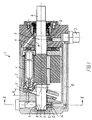
- the axial piston motor 1 shown in Figs. 1 and 2 comprises an enclosing housing 2, through which there is a flow of lubricant-free, water-based pressure fluid such as corporation water, which is supplied via a pressure inlet 3.
- the axial piston motor 1 may comprise five pistons 4, which via a known inclined disk construction 5 makes the drive shaft 6 of the motor rotate.
- Other numbers of pistons may be involved, however, because the idea of the invention concerns all piston engines regardless of the number of pistons.
- the drive shaft 6 is made of steel and comprises external sliding surfaces 7, which are supported against internal sliding surfaces 8 on the bearing liner 9 placed in the housing 2.
- the bearing liners may be designed as a bushing of a highly stable thermoplastic material on polyetheretherketone basis reinforced with carbon fibre.
- the housing 2 comprises a pressure fluid supporting duct 10, which ends at a recess 11 in a radially displaceable bearing part 12 in the internal sliding surface 8 in the bearing bushing 9.
- the bearing part is shaped as a slide shoe or a pressure piston 12 of circular cross section, which is secured by means of an intermediary O-ring 13 in a radial bore 14 in the housing 2.
- the pressure piston 12 is preferably made of the same plastic material as the bearing bushing 9.
- the pressure piston 12 comprises a bearing pressure rim or land 15, which delimits the recess 11 as well as a facing, hydrostatically actuated pressure surface 16, which acts on the pressure piston 12 with a force in the direction inwards towards the sliding surface 7 of the drive shaft 6.
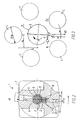
- Fig. 3 shows diagrammatically the pressure pistons 4, which are distributed around the drive shaft 6.
- the axially directed force of the pressure pistons is converted on the inclined disk shown in Fig. 2 into a resulting, horizontal component F S , see Fig. 3, which would mean that the journal bearing of the shaft is exposed to a radially directed load with the force F S in the point P.
- This force would involve an axially extended linear contact in the point P between the sliding surface of the shaft and the surrounding sliding surface.
- the point P lies diametrically opposite the vertex in the circular path of the pistons on the inclined disk.
- the rotation of the shaft causes a certain friction in the journal bearing.
- the arrow M marked in the drawing indicates the torque load of the shaft; the direction of rotation is opposed, i.e. in the drawing the shaft rotates against the arrow M, and thereby counterclockwise.
- the friction in the linear contact P causes the shaft to tend to roll on the sliding surface connected to the housing in the journal bearing.
- the rolling would cause the linear contact P to wander clockwise around on the sliding surface connected to the housing, i.e. in the same direction as indicated by the arrow M.
- the tendency towards rolling is equivalent to an addition of a frictional force to the radial force F S .
- the frictional force is perpendicular to F S and points to the left in the drawing.
- journal bearing Because of the actual linear contact in the point U, the journal bearing must exert a reactionary force, which is equal to the resulting force from the superposition of the force of the pistons and the frictional force.
- the major part of this reactionary force is exerted by the hydrostatic pressure that is built up in the recess 11.
- the centre of the recess is placed so that it coincides with the point U.
- the recess is circular, so that the intersection with the cylindrical shaft gives the edge of the recess a curved, ellipsoid shape.
- the areal centre of gravity of the recess must lie angularly displaced in relation to the theoretical point of contact P, which is determined by the geometry of the engine without taking into account the frictional forces. Placing the areal centre of gravity of the surface in the point U results in the fact that there are "equal parts of relief surface" on both sides of the line where there is actually a tendency to linear contact.
- the tangential or circumferential extent ⁇ of the recess 11 covers at least an angular area comprising the geometrical extremities in the high-load area for the transmission of the piston forces to the bearing surface 8 via the drive shaft 6 at the lowest, respectively the highest number of pressure actuated pistons for the motor in question during operation.
- Fig. 3 shows diagrammatically the parameters which have an influence in determining the angle ⁇ .
- the pressure piston 12 had an external diameter at the rim 15 of the pressure surface of 12.2 mm and an internal diameter of 10 mm (corresponding to the extent of the recess 11).
- the dimensioning with a view to ⁇ st was chosen in order to optimise the starting torque of the motor.
- the dimensioning should be based on the dynamic coefficient of friction.
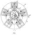
- the radial piston motor 20 shown diagrammatically in Fig. 4 comprises an enclosed housing 22, through which there is a flow of lubricant-free, water-based pressure fluid such as corporation water.
- the radial piston motor may comprise an optional number of pistons such as five pistons 23 in the embodiment shown. Via an eccentric part 24 the pistons 23 are connected drivingly to the drive shaft 25 of the rotor.
- the drive shaft 25 is made of steel and is supported in bearing bushings 26 of a highly stable plastic material, which are supported in the housing 22.
- the drive shaft 25 comprises a pressure-fluid supplying duct 27, which leads to a recess 28 shaped in a radially displaceable pressure piston 29 in the drive shaft 25.
- the geometrical pressure mean point P for pressure actuation of the radial piston motor 20 is indicated in the high-load area for the transmission of the piston forces F S to the bearing surface at the drive shaft 25.
- a mean point P which in a known manner can be established geometrically for the engine construction in question, depending on the number of pistons of the construction.
- the approximate centre of the radial extent of the recess on the bearing surface is angularly displaced by the angle ⁇ in the direction against the direction of rotation of the drive shaft 25, seen in relation to the mentioned geometrically determined mean point P of the pressure actuation.
- the angle a lies in the area 0-25° and increases with an increasing static friction coefficient ⁇ st between the bearing surfaces.
- the recesses are placed in pressure pistons, but the recesses may also be shaped direct in the bearing surface in question.
Landscapes
- Engineering & Computer Science (AREA)
- Mechanical Engineering (AREA)
- General Engineering & Computer Science (AREA)
- Chemical & Material Sciences (AREA)
- Combustion & Propulsion (AREA)
- Reciprocating Pumps (AREA)
- Sliding-Contact Bearings (AREA)
- Shafts, Cranks, Connecting Bars, And Related Bearings (AREA)
- Hydraulic Motors (AREA)
Claims (21)
- Moteur à pistons hydraulique destiné à fonctionner avec un fluide sous pression à base d'eau, sans lubrifiant, avec un arbre tournant (6; 25), qui est couplé à des pistons de travail (4; 23) et tourne dans un carter (2; 22) dans au moins un palier lisse radial, dans lequel une première surface métallique de glissement (8) est en regard d'une seconde surface de glissement (9) en matière plastique, caractérisé en ce que dans le palier lisse, dans une zone de sollicitation, qui est soumise à une sollicitation continue par une force radiale (Frl + Frp) pendant le fonctionnement sous l'influence des pistons de travail (4; 23), au moins un évidement (11) a été formé dans une des surfaces de glissement (9), lequel évidement est alimenté en fluide sous pression pendant le fonctionnement pour une absorption au moins partielle de la force radiale, et en ce que le centre de gravité (U) de surface de cet évidement (11) a subi un décalage angulaire (α) dans la direction opposée au sens de rotation de l'arbre (6) par rapport à une certaine position (P) déterminée par la géométrie du moteur, laquelle position (P) indique le centre de gravité de surface pour une surface où la charge radiale (Fs) exercée par les pistons de travail existerait sur la surface de glissement (9) concernée si le palier lisse était sans friction et sans évidement.
- Moteur à pistons hydrauliques selon la revendication 1, caractérisé en ce que le décalage angulaire (α) est supérieur à 0° et inférieur à 25°.
- Moteur à pistons hydrauliques selon la revendication 1 ou 2, caractérisé en ce que le décalage angulaire (α) est adapté au coefficient de frottement statique (µst) du palier lisse.
- Moteur à pistons hydrauliques selon la revendication 1 ou 2, caractérisé en ce que le décalage angulaire (α) est adapté au coefficient de frottement dynamique (µdy) du palier lisse.
- Moteur à pistons hydrauliques selon la revendication 1 ou 2, caractérisé en ce que le décalage angulaire (α) est adapté à un coefficient de frottement (µ) compris entre le coefficient de frottement dynamique (µdy) du palier lisse et le coefficient de frottement statique (µst) du palier lisse.
- Moteur à pistons hydrauliques selon l'une quelconque des revendications 1 à 5, caractérisé en ce que le palier lisse a un coefficient de frottement statique ou dynamique (µst, µdy), supérieur à 0 et inférieur à 0,3, et en ce que le décalage angulaire (α) est supérieur à 0° et inférieur à 8°.
- Moteur à pistons hydraulique selon l'une quelconque des revendications 1 à 6, dans lequel, pendant le fonctionnement, l'arbre tournant (6) est influencé par une force (Fs), dont la valeur et/ou la direction varie(nt) en accord avec un nombre variable de pistons de travail (4), déterminé par la géométrie du moteur (1), lesquels pistons de travail sont sollicités par une pression permanente, caractérisé en ce que le décalage angulaire (α) est adapté à la force (Fs) la plus grande qui survient.
- Moteur à pistons hydrauliques selon l'une quelconque des revendications 1 à 6, dans lequel l'arbre tournant (6) est influencé, pendant le fonctionnement, par une force (Fs) dont la valeur et/ou la direction varie(nt) en accord avec un nombre variable de pistons de travail (4), déterminé par la géométrie du moteur (1), lesquels pistons de travail sont sollicités par une pression permanente, caractérisé en ce que le décalage angulaire (α) est adapté à la force (Fs) la plus faible qui survient.
- Moteur à pistons hydrauliques selon l'une quelconque des revendications 1 à 6, dans lequel l'arbre tournant (6) est influencé, pendant le fonctionnement, par une force (Fs) dont la valeur et/ou la direction varie(nt) en accord avec un nombre variable de pistons de travail (4), déterminé par la géométrie du moteur (1), lesquels pistons de travail sont sollicités par une pression permanente, caractérisé en ce que le décalage angulaire (α) est adapté à une valeur de force (Fs) comprise entre la force la plus faible qui survient et la valeur de la force la plus grande qui survient.
- Moteur à pistons hydrauliques selon l'une quelconque des revendications 1 à 6, dans lequel l'arbre tournant (6) est influencé, pendant le fonctionnement, par une force (Fs) dont la valeur et/ou la direction varie(nt) en accord avec un nombre variable de pistons de travail (4), déterminé par la géométrie du moteur (1), lesquels pistons de travail sont sollicités par une pression permanente, caractérisé en ce que l'étendue tangentielle de l'évidement (11) couvre au moins une plage angulaire (β) qui comporte les points extrêmes pour l'influence de la force radiale (Fs) sur la surface de glissement (8) concernée.
- Moteur à pistons hydrauliques selon l'une quelconque des revendications précédentes, caractérisé en ce que l'évidement (11) est alimenté en fluide sous pression par l'intermédiaire d'un dispositif (10) à étranglement.
- Moteur à pistons hydrauliques selon l'une quelconque des revendications précédentes, caractérisé en ce que le dispositif à étranglement est un conduit (10) à étranglement qui débouche dans l'évidement (11).
- Moteur à pistons hydrauliques selon l'une quelconque des revendications précédentes, caractérisé en ce que l'évidement (11) a été formé dans un sabot mobile coulissant (12), et en ce que l'évidement (11) est entouré par un méplat (15) formé sur le sabot coulissant (12), lequel méplat fait partie d'une surface de glissement (8).
- Moteur à pistons hydrauliques selon la revendication 13, caractérisé en ce que le conduit (10') à étranglement est formé dans le sabot coulissant (12).
- Moteur à pistons hydrauliques selon la revendication 14, caractérisé en ce que le sabot coulissant est un piston cylindrique (12) fixé de manière coulissante dans un alésage (14) qui débouche sur une des surfaces de glissement (8).
- Moteur à pistons hydrauliques selon la revendication 15, caractérisé en ce que le piston cylindrique (12) a une première surface (8) d'extrémité, où sont formés l'évidement (11) et le méplat (15), et une second surface (16) d'extrémité, située en regard, qui comporte une entrée du conduit (10') à étranglement, et qui subit l'influence, pendant le fonctionnement, d'un fluide sous pression qui est conduit jusqu'à l'alésage (14).
- Moteur à pistons hydrauliques selon l'une quelconque des revendications précédentes, où l'arbre (25) peut tourner par rapport aux pistons de travail (23), et où le palier lisse est un palier radial, caractérisé en ce que l'évidement (28) est placé dans une surface de glissement sur l'arbre (25), et en ce que l'arbre (25) comporte au moins un passage (27) relié à l'évidement (28) pour fournir un fluide sous pression à l'évidement (28).
- Moteur à pistons hydrauliques selon l'une quelconque des revendications 1 à 16, où les pistons de travail (4) tournent avec l'arbre (6) par rapport à un carter fixe (2), et où le palier lisse est un palier radial, caractérisé en ce que l'évidement (11) est placé dans une surface de glissement (8) dans le carter (2), et en ce que le carter (2) comporte au moins un passage (10) relié à l'évidement (11) pour fournir un fluide sous pression à l'évidement (11).
- Moteur à pistons hydrauliques selon l'une quelconque des revendications précédentes, caractérisé en ce que la matière plastique est un polyrayléthercétone.
- Moteur à pistons hydrauliques selon la revendication 9, caractérisé en ce que la matière plastique est du polyétheréthercétone.
- Moteur à pistons hydrauliques selon l'une quelconque des revendications précédentes, caractérisé en ce que la matière plastique est renforcée par des fibres.
Applications Claiming Priority (4)
| Application Number | Priority Date | Filing Date | Title |
|---|---|---|---|
| DK931374A DK137493D0 (da) | 1993-12-08 | 1993-12-08 | Hydraulisk stempelmotor |
| DK1374/93 | 1993-12-08 | ||
| DK137493 | 1993-12-08 | ||
| PCT/DK1994/000454 WO1995016129A1 (fr) | 1993-12-08 | 1994-12-05 | Moteur a pistons hydrauliques |
Publications (2)
| Publication Number | Publication Date |
|---|---|
| EP0733164A1 EP0733164A1 (fr) | 1996-09-25 |
| EP0733164B1 true EP0733164B1 (fr) | 2001-01-17 |
Family
ID=8104160
Family Applications (1)
| Application Number | Title | Priority Date | Filing Date |
|---|---|---|---|
| EP95903260A Expired - Lifetime EP0733164B1 (fr) | 1993-12-08 | 1994-12-05 | Moteur a pistons hydrauliques |
Country Status (6)
| Country | Link |
|---|---|
| US (1) | US5685215A (fr) |
| EP (1) | EP0733164B1 (fr) |
| AU (1) | AU1219095A (fr) |
| DE (1) | DE69426605T2 (fr) |
| DK (1) | DK137493D0 (fr) |
| WO (1) | WO1995016129A1 (fr) |
Families Citing this family (18)
| Publication number | Priority date | Publication date | Assignee | Title |
|---|---|---|---|---|
| DE4424610C2 (de) * | 1994-07-13 | 1999-11-11 | Danfoss As | Hydraulische Kolbenmaschine |
| DE4424607A1 (de) * | 1994-07-13 | 1996-01-18 | Danfoss As | Hydraulische Axialkolbenmaschine |
| DE4424672A1 (de) * | 1994-07-13 | 1996-01-18 | Danfoss As | Kolben-Gleitschuh-Anordnung |
| DE19532713C1 (de) * | 1995-09-05 | 1997-02-06 | Danfoss As | Hydraulische Radialkolbenmaschine |
| DE19636274C2 (de) * | 1996-09-06 | 2001-07-26 | Sauer Sundstrand Gmbh & Co | Gleitlager mit selbsteinstellender Tragfähigkeit |
| JPH10213062A (ja) * | 1997-01-31 | 1998-08-11 | Zexel Corp | 可変容量型斜板式圧縮機 |
| SE514384C2 (sv) * | 1998-04-17 | 2001-02-19 | Parker Hannifin Ab | Hydraulisk roterande axialkolvmaskin |
| ATE326632T1 (de) * | 2001-07-05 | 2006-06-15 | Sarcos Lc | Schnell ansprechende energieumwandlungsvorrichtung |
| US7216579B2 (en) | 2001-10-17 | 2007-05-15 | Lonmore, L.C. | Variable flow control devices, related applications, and related methods |
| ITGE20020064A1 (it) * | 2002-07-16 | 2004-01-16 | Ultraflex Spa | Pompa oleodinamica per sistemi di guida per imbarcazioni |
| JP4701735B2 (ja) * | 2004-07-09 | 2011-06-15 | 株式会社豊田自動織機 | 摺動部材 |
| US7066116B2 (en) * | 2004-07-29 | 2006-06-27 | Sarcos Investments Lc | Valve system for a rapid response power conversion device |
| US7363887B2 (en) * | 2004-12-02 | 2008-04-29 | Raytheon Sarcos, Llc | Dynamic mass transfer rapid response power conversion system |
| GB0509787D0 (en) * | 2005-05-12 | 2005-06-22 | Brisland M J | Fluid powered motor or pump |
| DE102006058355A1 (de) * | 2006-03-10 | 2007-09-13 | Brueninghaus Hydromatik Gmbh | Kombi-Pumpengehäuse für mehrere Nenngrößen |
| WO2008156897A2 (fr) * | 2007-04-05 | 2008-12-24 | Raytheon Sarcos, Llc | Système de conversion de puissance à réaction et à allumage rapides |
| US8550792B2 (en) * | 2008-06-30 | 2013-10-08 | Eaton Corporation | Energy conversion device and method of reducing friction therein |
| JP7657094B2 (ja) * | 2021-04-30 | 2025-04-04 | 日本発條株式会社 | 屈曲構造体 |
Family Cites Families (6)
| Publication number | Priority date | Publication date | Assignee | Title |
|---|---|---|---|---|
| US3838942A (en) * | 1971-07-30 | 1974-10-01 | Mitchell J Co | Refrigeration compressor |
| AT357822B (de) * | 1973-04-24 | 1980-08-11 | Seibert Josef | Triebwerk fuer eine hubkolbenmaschine, insbesondere brennkraftmaschine |
| US3872775A (en) * | 1973-09-25 | 1975-03-25 | Robert Cecil Clerk | Swash-plate bearings for axial piston pumps or motors |
| US5055004A (en) * | 1990-05-23 | 1991-10-08 | General Motors Corporation | Stroke control assembly for a variable displacement compressor |
| JPH06503137A (ja) * | 1990-12-17 | 1994-04-07 | ツェントラルニイ ナウチノ−イススレドヴァテルスキイ アヴトモビルニイ イ アヴトモトルニイ インスティトゥト | アキシャルピストン機械 |
| EP0512138B1 (fr) * | 1991-05-07 | 1994-08-24 | Hauhinco Maschinenfabrik G. Hausherr, Jochums Gmbh & Co. Kg | Pompe à eau à haute pression pour eau purifiée |
-
1993
- 1993-12-08 DK DK931374A patent/DK137493D0/da not_active Application Discontinuation
-
1994
- 1994-12-05 DE DE69426605T patent/DE69426605T2/de not_active Expired - Lifetime
- 1994-12-05 EP EP95903260A patent/EP0733164B1/fr not_active Expired - Lifetime
- 1994-12-05 WO PCT/DK1994/000454 patent/WO1995016129A1/fr not_active Ceased
- 1994-12-05 AU AU12190/95A patent/AU1219095A/en not_active Abandoned
- 1994-12-05 US US08/652,588 patent/US5685215A/en not_active Expired - Lifetime
Also Published As
| Publication number | Publication date |
|---|---|
| AU1219095A (en) | 1995-06-27 |
| DE69426605D1 (de) | 2001-02-22 |
| EP0733164A1 (fr) | 1996-09-25 |
| WO1995016129A1 (fr) | 1995-06-15 |
| DE69426605T2 (de) | 2001-08-02 |
| US5685215A (en) | 1997-11-11 |
| DK137493D0 (da) | 1993-12-08 |
Similar Documents
| Publication | Publication Date | Title |
|---|---|---|
| US5685215A (en) | Hydraulic piston engine driven by a lubricant-free, water-based fluid | |
| US5951169A (en) | Thrust bearing | |
| EP0396441B1 (fr) | Joint frontal sans contact pour les deux sens de rotation | |
| US7108493B2 (en) | Variable displacement pump having rotating cam ring | |
| US7731476B2 (en) | Method and device for reducing axial thrust and radial oscillations and rotary machines using same | |
| EP0970315A1 (fr) | Palier de butee | |
| CA2493686C (fr) | Palier de couronne a cames pour systeme d'alimentation en combustible | |
| CA2715436C (fr) | Pompe a cylindre variable a cage ovale rotative | |
| CN1646788A (zh) | 带有速度控制轴承的摆动盘式切割器 | |
| EP1165979B1 (fr) | Palier hybride | |
| JPH06501524A (ja) | リファイナ中のベアリング装置 | |
| US4508011A (en) | Hydraulic axial piston machine | |
| WO1995016128A1 (fr) | Moteur hydraulique a pistons | |
| US4890796A (en) | Combined hydrostatic/hydrodynamic bearing system for grinding apparatus | |
| EP0733165B1 (fr) | Portee de tourillon radiale a coulisse, et coulisse pour portee de tourillon radiale | |
| EP1247990A1 (fr) | Pompe centrifuge avec commande axiale auto-équilibrante | |
| CN220081736U (zh) | 压缩机叶轮轴支承密封结构 | |
| US6109792A (en) | Combination stack tightener and journal bearing assembly | |
| CN223594344U (zh) | 一种传动机构 | |
| CA2212433C (fr) | Palier axial hydraulique | |
| RU2159374C2 (ru) | Затворное торцовое уплотнение | |
| WO1993011358A1 (fr) | Double support d'excentrique oppose pour compresseur a piston rotatif | |
| KR20190125946A (ko) | 비원형 베어링 보어를 갖는 터보차저 베어링 하우징 |
Legal Events
| Date | Code | Title | Description |
|---|---|---|---|
| PUAI | Public reference made under article 153(3) epc to a published international application that has entered the european phase |
Free format text: ORIGINAL CODE: 0009012 |
|
| 17P | Request for examination filed |
Effective date: 19960603 |
|
| AK | Designated contracting states |
Kind code of ref document: A1 Designated state(s): DE FR GB IT |
|
| 17Q | First examination report despatched |
Effective date: 19980609 |
|
| GRAG | Despatch of communication of intention to grant |
Free format text: ORIGINAL CODE: EPIDOS AGRA |
|
| GRAG | Despatch of communication of intention to grant |
Free format text: ORIGINAL CODE: EPIDOS AGRA |
|
| GRAH | Despatch of communication of intention to grant a patent |
Free format text: ORIGINAL CODE: EPIDOS IGRA |
|
| GRAH | Despatch of communication of intention to grant a patent |
Free format text: ORIGINAL CODE: EPIDOS IGRA |
|
| GRAA | (expected) grant |
Free format text: ORIGINAL CODE: 0009210 |
|
| AK | Designated contracting states |
Kind code of ref document: B1 Designated state(s): DE FR GB IT |
|
| PG25 | Lapsed in a contracting state [announced via postgrant information from national office to epo] |
Ref country code: IT Free format text: LAPSE BECAUSE OF FAILURE TO SUBMIT A TRANSLATION OF THE DESCRIPTION OR TO PAY THE FEE WITHIN THE PRE;WARNING: LAPSES OF ITALIAN PATENTS WITH EFFECTIVE DATE BEFORE 2007 MAY HAVE OCCURRED AT ANY TIME BEFORE 2007. THE CORRECT EFFECTIVE DATE MAY BE DIFFERENT FROM THE ONE RECORDED.SCRIBED TIME-LIMIT Effective date: 20010117 Ref country code: FR Free format text: LAPSE BECAUSE OF FAILURE TO SUBMIT A TRANSLATION OF THE DESCRIPTION OR TO PAY THE FEE WITHIN THE PRESCRIBED TIME-LIMIT Effective date: 20010117 |
|
| REF | Corresponds to: |
Ref document number: 69426605 Country of ref document: DE Date of ref document: 20010222 |
|
| EN | Fr: translation not filed | ||
| PLBE | No opposition filed within time limit |
Free format text: ORIGINAL CODE: 0009261 |
|
| STAA | Information on the status of an ep patent application or granted ep patent |
Free format text: STATUS: NO OPPOSITION FILED WITHIN TIME LIMIT |
|
| PG25 | Lapsed in a contracting state [announced via postgrant information from national office to epo] |
Ref country code: GB Free format text: LAPSE BECAUSE OF NON-PAYMENT OF DUE FEES Effective date: 20011205 |
|
| REG | Reference to a national code |
Ref country code: GB Ref legal event code: IF02 |
|
| 26N | No opposition filed | ||
| GBPC | Gb: european patent ceased through non-payment of renewal fee |
Effective date: 20011205 |
|
| PGFP | Annual fee paid to national office [announced via postgrant information from national office to epo] |
Ref country code: DE Payment date: 20091203 Year of fee payment: 16 |
|
| PG25 | Lapsed in a contracting state [announced via postgrant information from national office to epo] |
Ref country code: DE Free format text: LAPSE BECAUSE OF NON-PAYMENT OF DUE FEES Effective date: 20110701 |
|
| REG | Reference to a national code |
Ref country code: DE Ref legal event code: R119 Ref document number: 69426605 Country of ref document: DE Effective date: 20110701 |