EP0733385A2 - Knieschützer für Sportler - Google Patents
Knieschützer für Sportler Download PDFInfo
- Publication number
- EP0733385A2 EP0733385A2 EP96109361A EP96109361A EP0733385A2 EP 0733385 A2 EP0733385 A2 EP 0733385A2 EP 96109361 A EP96109361 A EP 96109361A EP 96109361 A EP96109361 A EP 96109361A EP 0733385 A2 EP0733385 A2 EP 0733385A2
- Authority
- EP
- European Patent Office
- Prior art keywords
- knee
- pads
- protector according
- protector
- cushion
- Prior art date
- Legal status (The legal status is an assumption and is not a legal conclusion. Google has not performed a legal analysis and makes no representation as to the accuracy of the status listed.)
- Granted
Links
Images


Classifications
-
- A—HUMAN NECESSITIES
- A41—WEARING APPAREL
- A41D—OUTERWEAR; PROTECTIVE GARMENTS; ACCESSORIES
- A41D13/00—Professional, industrial or sporting protective garments, e.g. surgeons' gowns or garments protecting against blows or punches
- A41D13/05—Professional, industrial or sporting protective garments, e.g. surgeons' gowns or garments protecting against blows or punches protecting only a particular body part
- A41D13/055—Protector fastening, e.g. on the human body
- A41D13/0556—Protector fastening, e.g. on the human body with releasable fastening means
- A41D13/0568—Protector fastening, e.g. on the human body with releasable fastening means with straps
-
- A—HUMAN NECESSITIES
- A63—SPORTS; GAMES; AMUSEMENTS
- A63B—APPARATUS FOR PHYSICAL TRAINING, GYMNASTICS, SWIMMING, CLIMBING, OR FENCING; BALL GAMES; TRAINING EQUIPMENT
- A63B71/00—Games or sports accessories not covered in groups A63B1/00 - A63B69/00
- A63B71/08—Body-protectors for players or sportsmen, i.e. body-protecting accessories affording protection of body parts against blows or collisions
- A63B71/12—Body-protectors for players or sportsmen, i.e. body-protecting accessories affording protection of body parts against blows or collisions for the body or the legs, e.g. for the shoulders
- A63B71/1225—Body-protectors for players or sportsmen, i.e. body-protecting accessories affording protection of body parts against blows or collisions for the body or the legs, e.g. for the shoulders for the legs, e.g. thighs, knees, ankles, feet
-
- A—HUMAN NECESSITIES
- A41—WEARING APPAREL
- A41D—OUTERWEAR; PROTECTIVE GARMENTS; ACCESSORIES
- A41D13/00—Professional, industrial or sporting protective garments, e.g. surgeons' gowns or garments protecting against blows or punches
- A41D13/015—Professional, industrial or sporting protective garments, e.g. surgeons' gowns or garments protecting against blows or punches with shock-absorbing means
- A41D13/0153—Professional, industrial or sporting protective garments, e.g. surgeons' gowns or garments protecting against blows or punches with shock-absorbing means having hinged or separable parts
-
- A—HUMAN NECESSITIES
- A63—SPORTS; GAMES; AMUSEMENTS
- A63B—APPARATUS FOR PHYSICAL TRAINING, GYMNASTICS, SWIMMING, CLIMBING, OR FENCING; BALL GAMES; TRAINING EQUIPMENT
- A63B71/00—Games or sports accessories not covered in groups A63B1/00 - A63B69/00
- A63B71/08—Body-protectors for players or sportsmen, i.e. body-protecting accessories affording protection of body parts against blows or collisions
- A63B71/12—Body-protectors for players or sportsmen, i.e. body-protecting accessories affording protection of body parts against blows or collisions for the body or the legs, e.g. for the shoulders
- A63B71/1225—Body-protectors for players or sportsmen, i.e. body-protecting accessories affording protection of body parts against blows or collisions for the body or the legs, e.g. for the shoulders for the legs, e.g. thighs, knees, ankles, feet
- A63B2071/125—Body-protectors for players or sportsmen, i.e. body-protecting accessories affording protection of body parts against blows or collisions for the body or the legs, e.g. for the shoulders for the legs, e.g. thighs, knees, ankles, feet for the knee
Definitions
- the invention relates to a joint protector, in particular knee protectors according to the preamble of claim 1.
- a generic protection device is known from US Pat. No. 3,772,704.
- An upper fastening strip connects an upper pad part to the thigh.
- a total of three lower fastening strips connect a lower cushion part to the lower leg, so that the shin and the kneecap are covered.
- Knee guards are used in sports where the athlete can regularly expect contact with the ground, especially in indoor sports such as volleyball and handball.
- the knee with its various exposed areas which will be discussed later, is particularly sensitive to injury and pain.
- Knee protectors of the type mentioned, such as those sold by the applicant under the name "pro-tection indoor knee protection” have at least padded areas which face the patella, the two on the side of the patella on the thigh bone (Os femoris) lateral and medial epicondyle, which include the tibial tuberosity below the kneecap on the tibia and the lateral and medial condyle lying to the side of it.
- the fibulae of the fibula is also padded.
- the knee pads split the upholstery part like a check into individual pads.
- the knee is fastened by a stocking part, the individual pads being inserted into the stocking part between two textile layers.
- knee protectors of the type described here are that when the knee is bent, abrasion movements between the cushion area and the skin necessarily occur. This is because the knee is stretched in the front midline, i.e. a connecting line between fixed points on the thigh on the one hand and the shin on the other hand is extended when the knee is bent or shortened when the knee is stretched. Corresponding shortenings also take place in the hollow of the knee, i.e. a line connecting fixed points on the back of the thigh and on the calf shortens when the knee is bent and lengthens when the knee is extended. The elasticity of the material cannot fully compensate for this. This leads to displacements of the upholstery in relation to the areas of the leg to be protected, so that an optimal protective effect can only be achieved in certain positions of the knee. The constant relative movements can also cause the entire knee protector to slip into a position in which optimal protection is no longer possible.
- the present invention is based on the object of providing a joint protector of the type mentioned at the outset which enables improved protection for the exposed parts of the joint regardless of the flexion position. This is also to avoid the risk of the protector shifting and slipping during use.
- the invention proposes a joint protector according to claim 1.
- the joint can be bent against one another without moving the fastening parts.
- the cushion area is carried along, for example, for the patella with the lower fastening strip in an anatomically correct manner in accordance with the flexion, so that it is protected by the individual cushion provided for this purpose, both when the joint is bent and when it is stretched.
- the two cushion areas are displaceable due to the elastic area.
- the elastic area makes it easier to bend the knee.
- the two padding areas could in principle comprise large pads that match the shape of the knee.
- the division into individual pads, which serve to protect certain exposed areas of the knee and are assigned to them, is more favorable.
- the relevant areas have already been mentioned above.
- the lower pad area includes pads to protect the lateral and medial condyles of the tibia
- the upper pad area includes pads to protect the lateral and medial epicondyles and femurs
- the lower pad area below the Padding for the kneecap comprises at least one additional pad to protect the tibial tuberosity
- approximately three similar pads for the kneecap and tuberosity tibiae are arranged in a substantially vertical line with each other, which advantageously can be formed in a similar manner in the form of regular hexagons, which are honeycomb-like with horizontal abutting lines lie among each other. Furthermore, it is possible that laterally adjoining the three cushions mentioned, at least in the connection area, insert like a honeycomb with a delimitation angle of approximately 120 °.
- Each of the butt lines enables a relatively force-free deflection of the individual cushions against one another and thus a spatial adaptation along horizontal and two diagonal intersecting edges.
- the elastic region can preferably have an approximately constant width between the two cushion regions, which is dimensioned so small that no larger unpadded zones arise and, viewed from the front, bell-bell-like above the cushion for the patella and in each case below the cushion for the lateral epicondyle and medial course. This in turn ensures in an anatomically correct manner that the two last-mentioned cushions are held essentially immovably relative to the thigh, regardless of the flexion of the knee, while all other cushions are displaced together with the movement of the lower leg.
- the upper pad area and the lower pad area each consist of a thinner base layer and pads placed thereon, which preferably differ from one another only in shape, i.e. both parts are made of a uniform, same material, in particular a foam material.
- the base layer between the pad for the patella and the pad for the lateral and medial condyles can each have an incision starting from the outer edge.
- the entire upholstery part can be constructed in such a way that the two upholstery areas are sewn with an interposed elastic area on the respective boundary edges.
- the padded areas can be covered with fabric or preferably laminated. This can easily be represented at the same time as a corresponding shaping process. It is also possible to flock the cushion areas only after the molding process.
- the fastening strips which advantageously also consist of textile material, can be produced in one piece with the textile carrier material mentioned. However, it may also be cheaper for manufacturing reasons to sew them onto the upholstery part.
- the two strips can be in one piece and start from one edge of the upholstery part and are brought up to the other edge of the upholstery part and fastened there. It is also possible to design the fastening strips in two parts in the form of shorter tabs, which are then connected approximately in the middle.
- the lower fastening strip is advantageously fastened at both ends and closed in a ring shape with the cushion part, while only the upper fastening strip can be opened and closed.
- Velcro fasteners are to be provided as a suitable and practical type of fastener for the fastening strips.
- a knee protector for a left knee would be mirrored symmetrically in a frontal view on a vertical median plane.
- knee pads for both knees can also be standardized using a symmetrical design.
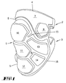
- FIG. 1 shows a knee protector with a cushion part 1 and fastening strips 2, 3 adjoining it.
- the cushion part 1 encloses the front parts of a knee, while the fastening strips are provided for laying around the thigh or lower leg immediately above or below the hollow of the knee.
- the cushion part 1 is composed of an upper cushion area 4 and a lower cushion area 5, between which an elastic area 6 is provided.
- the elastic region consists of a carrier layer 16 for the cushion regions 4 and 5 and at the same time forms the fastening strips 2 and 3 in one piece.
- the cushion area 4 consists of a thinner base layer 7 and pads placed thereon, of which one of the pads 8 is placed and recognizable for the medial epicondyle.
- the cushion area 5 consists of a thinner base layer 9, which carries a plurality of pads, of which the pad 10 for protecting the patella, pads 11 and 12 for protecting the tibial tuberosity and pads 13, 14 for protecting the condyle are shown and recognizable in particular medialis.
- the pads 10, 11 and 12 are regularly hexagonal and abut with horizontal ones Edges while maintaining a certain distance from each other.
- the cushions 13 and 14 adjoin the sides with angles of approximately 120 ° in the connection area.
- An incision 15 in the material of the thinner base layer is provided between the pads 10 and 13 to increase the flexibility of the pad part.
- the pads are glued or sewn onto the carrier material 16, which also forms the elastic region 6.
- FIGS. 2 and 3 which are described jointly below, corresponding details as in FIG. 1 are given the same numbers. This will not be discussed in more detail.
- the free end of the fastening strip 2 can also be seen, which can be fixed to the carrier material 16, in particular by means of a Velcro fastener.
- an approximately symmetrical cushion 17 for the lateral epicondyle is formed on the upper cushion region 4 opposite the cushion 8.
- two individual pads 20, 18 are provided opposite the elongate pad 13 for the medial condyle, 18, while an approximately similar pad 19 for the caput fibulae is arranged symmetrically opposite the pad 14.
- FIG. 1 compared to FIG. 1, the free end of the fastening strip 2 can also be seen, which can be fixed to the carrier material 16, in particular by means of a Velcro fastener.
- an approximately symmetrical cushion 17 for the lateral epicondyle is formed on the upper cushion region 4 opposite the cushion 8.
- two individual pads 20, 18 are provided opposite the elongate pad 13 for the medial
- the bones meeting in the area of the knee are shown in a front view and in a side view, the exposed injury and pain-sensitive areas being shown in the drawing.
- the os femoris C f thigh bone
- the tibia T shin bone
- the fibula F fibula
- the first is the lateral condyle C 1 and the condyle medalis C m as well as the tuberosity tibiae T t marked.
- the caput fibulae F c is specially marked on the fibula.
- the patella R (kneecap) lies at a distance from the lower end of the femur.
- FIGS. 5 and 6 show a knee protector in the view according to FIG. 3, however in FIG. 5 in an extended position and in FIG. 6 in a bent position.
- the contour of the knee area K and parts of the aforementioned bones are drawn in the assigned position with thin lines.
- the geometry of a triangle which is composed of a point on the pad 10 and points on the pads 13 and 14, is only insignificant compared to that when the joint is bent, which is associated with an expansion of the elastic region 6
- Bone parts of the patella R and tibia T changed and that the same applies to a point on the pad 8 opposite the femoral c f .
- the courses of the upper edge 22 change significantly compared to the lower edge 23 of the knee protector, which are essentially formed by the fastening strips 2, 3.
Landscapes
- General Health & Medical Sciences (AREA)
- Physical Education & Sports Medicine (AREA)
- Health & Medical Sciences (AREA)
- Engineering & Computer Science (AREA)
- Textile Engineering (AREA)
- Orthopedics, Nursing, And Contraception (AREA)
- Professional, Industrial, Or Sporting Protective Garments (AREA)
- Ultra Sonic Daignosis Equipment (AREA)
- Surface Acoustic Wave Elements And Circuit Networks Thereof (AREA)
- Pyrane Compounds (AREA)
- Dental Preparations (AREA)
- Nitrogen Condensed Heterocyclic Rings (AREA)
- Materials For Medical Uses (AREA)
- Prostheses (AREA)
Abstract
Description
- Die Erfindung betrifft einen Gelenkschützer, insbesondere Knieschützer gemäß Gattungsbegriff des Anspruches 1.
- Eine gattungsgemäße Schutzvorrichtung ist aus dem US-Patent3,772,704 her bekannt. Ein oberer Befestigungsstreifen verbindet einen oberen Polsterteil mit dem Oberschenkel. Insgesamt drei untere Befestigungsstreifen verbinden ein unteres Polsterteil mit dem Unterschenkel, so daß das Schienbein und die Kniescheibe überdeckt sind.
- Knieschützer kommen bei solchen Sportarten zum Einsatz, bei denen der Sportler regelmäßig mit Bodenkontakt zu rechnen hat, insbesondere bei Hallensportarten wie Volleyball und Handball. Neben dem Ellenbogen, für den besondere, anders aufgebaute Schützer zum Einsatz kommen, ist insbesondere das Knie mit seinen verschieden exponierten Stellen, auf die später noch eingegangen wird, besonders verletzungs- und schmerzempfindlich. Knieschützer der genannten Art, wie beispielsweise von der Anmelderin unter der Bezeichnung "pro-tection Indoor-Knie-Schutz" vertrieben werden, weisen zumindest Polsterbereiche auf, die die Kniescheibe (Patella), die beiden seitlich der Kniescheibe am Oberschenkelknochen (Os femoris) zu findenden Epicondylus lateralis und medialis, die unterhalb der Kniescheibe am Schienbein (Tibia) liegende Tuberositas tibiae und die seitlich davon liegenden Condylus lateralis und medialis umfassen. In bevorzugter Weise ist auch das Caput fibulae des Wadenbeins (Fibula) abgepolstert. Um die Polsterbereiche auch bei einem Beugen des Knies in Anlage mit dem Knie halten zu können, ist bei den obengenannten Knieschützern das Polsterteil karoartig in Einzelpolster aufgeteilt. Die Befestigung am Knie erfolgt durch ein Strumpfteil, wobei die Einzelpolster in das Strumpfteil zwischen zwei textilen Lagen eingelegt sind.
- Der Nachteil bei Knieschützern der hier beschriebenen Art liegt darin, daß es bei einem Beugen des Knies notwendigerweise zu Scheuerbewegungen zwischen Polsterbereich und Haut kommt. Dies liegt darin begründet, daß das Knie vorne in der Längsmittelinie eine Streckung erfährt, d.h. eine Verbindungslinie zwischen Fixpunkten auf dem Oberschenkel einerseits und dem Schienbein andererseits verlängert sich bei einem Beugen des Knies, bzw. verkürzt sich bei einem Strecken des Knies. Weiterhin finden entsprechende Verkürzungen in der Kniekehle statt, d.h. eine Verbindungslinie zwischen Fixpunkten auf der Rückseite des Oberschenkels und auf der Wade verkürzt sich bei einem Beugen des Knies und verlängert sich beim Strecken des Knies. Die Elastizität des Material kann dies nicht vollständig ausgleichen. Es kommt somit zu Verschiebungen der Polster gegenüber den darunterliegenden zu schützenden Bereichen des Beines, so daß ein optimaler Schutzeffekt nur in bestimmten Stellungen des Knies erreicht werden kann. Die fortwährenden Relativbewegungen können außerdem dazu führen, daß der gesamte Knieschützer in eine Position verrutscht, in der kein optimaler Schutz mehr möglich ist.
- Hiervon ausgehend liegt der vorliegenden Erfindung die Aufgabe zugrunde, einen Gelenkschützer der eingangs genannten Art bereitzustellen, der einen verbesserten Schutz für die exponierten Partien des Gelenkes unabhängig von der Beugestellung ermöglicht. Hiermit soll zugleich die Gefahr eines Verschiebens und Verrutschens des Schützers im Gebrauch vermieden werden.
- Zur Lösung schlägt die Erfindung einen Gelenkschützer gemäß dem Anspruch 1 vor.
- Die Unteransprüche stellen vorteilhafte Weiterbildungen dar.
- Mit den hiermit vorgeschlagenen Mitteln wird einerseits erreicht, daß ein Beugen des Gelenks ohne Verschiebebewegung der Befestigungsteile gegeneinander erfolgen kann. Weiterhin wird der Polsterbereich beispielsweise für die Kniescheibe mit dem unteren Befestigungsstreifen in anatomisch richtiger Weise gemäß der Beugung mitgeführt, so daß diese sowohl bei gebeugtem als auch bei gestrecktem Gelenk jeweils von dem hierfür vorgesehenen Einzelpolster geschützt ist.
- Die beiden Polsterbereiche, sind infolge des elastischen Bereiches gegeneinander verschiebbar. Der elastische Bereich erleichtert somit die Beugebewegung des Knies.
- Die beiden Polsterbereiche könnten grundsätzlich großflächige, der Form des Knies angepaßte Polster umfassen. Günstiger ist jedoch die Aufgliederung in Einzelpolster, die zum Schutz bestimmter exponierter Bereiche des Knies dienen und diesen zugeordnet sind. Die entsprechenden Bereiche sind oben bereits angesprochen worden.
- So ist in bevorzugter Ausführung vorgesehen, daß der untere Polsterbereich Polster zum Schutz der Condylus lateralis und medialis der Tibia umfaßt, daß weiter der obere Polsterbereich Polster zum Schutz der Epicondylus lateralis und medialis des Os femoris umfaßt und daß schließlich der untere Polsterbereich unterhalb des Polsters für die Kniescheibe zumindest ein weiteres Polster zum Schutz der Tuberositas tibiae umfaßt.
- Hierbei kann dann weiterhin vorgesehen sein, daß in im wesentlichen senkrechter Linie untereinander etwa drei gleichartige Polster für die Kniescheibe und die Tuberositas tibiae angeordnet sind, wobei diese in günstiger Weise im wesentlichen gleichartig in Form von regelmäßigen Sechsecken ausgebildet sein können, die mit horizontalen Stoßlinien wabenartig untereinander liegen. Weiterhin ist es möglich, daß sich an die drei genannten Polster seitlich anschließende Polster zumindest im Anschlußbereich wabenartig mit einem Begrenzungswinkel von etwa 120° einfügen. Jede der Stoßlinien ermöglicht hierbei eine relativ kraftfreie Abbeugung der Einzelpolster gegeneinander und somit eine räumliche Anpassung entlang horizontaler und zweier diagonaler sich kreuzender Kanten.
- Der elastische Bereich kann in bevorzugter Weise zwischen den beiden Polsterbereichen etwa konstante Breite aufweisen, die so gering bemessen ist, daß keine größeren ungepolsterten Zonen entstehen und in Ansicht von vorne glockenkurvenartig oberhalb des Polsters für die Kniescheibe und jeweils unterhalb der Polster für die Epicondylus lateralis und medialis verlaufen. Hiermit wird wiederum in anatomisch richtiger Weise sichergestellt, daß die beiden zuletzt genannten Polster unabhängig von der Beugung des Knies im wesentlichen unverschieblich gegenüber dem Oberschenkel gehalten werden, während alle weiteren Polster sich mit der Bewegung des Unterschenkels demgegenüber gemeinsam verlagern.
- In herstellungstechnisch günstiger Ausführung wird vorgesehen, daß der obere Polsterbereich und der untere Polsterbereich jeweils aus einer dünneren Grundschicht und darauf aufgesetzten Polstern besteht, die sich vorzugsweise nur durch die Formgebung voneinander unterscheiden, d.h. beide Teile sind aus einem einheitlichen gleichen Material, insbesondere aus einem Schaumstoffmaterial. Zur Erhöhung der bereits angesprochenen Biegsamkeit und Flexibilität kann die Grundschicht zwischen dem Polster für die Patella und den Polstern für die Condylus lateralis und medialis jeweils einen von der Außenkante ausgehenden Einschnitt aufweisen.
- Das gesamte Polsterteil kann so aufgebaut sein, daß die beiden Polsterbereiche mit einem dazwischengesetzten elastischen Bereich an den jeweiligen Begrenzungskanten vernäht sind. Es ist jedoch auch möglich, die Polsterbereiche auf ein Trägermaterial jeweils zumindest entlang ihrer Begrenzungskanten aufzunähen, wobei das Trägermaterial zugleich den elastischen Bereich ausbildet. An die Stelle eines Aufnähens kann auch ein Aufkleben treten. Aus optischen Gründen und um die Rutschfähigkeit des Knieschützers auf dem Hallenuntergrund zu erhöhen, können die Polsterbereiche stoffüberzogen oder bevorzugt kaschiert sein. Dies läßt sich gleichzeitig mit einem entsprechenden Ausformungsprozeß ohne weiteres darstellen. Es ist auch möglich, die Polsterbereiche erst nach dem Ausformungsprozeß zu beflocken.
- Die Befestigungsstreifen, die günstigerweise ebenfalls aus textilem Material bestehen, können einstückig mit dem genannten textilen Trägermaterial hergestellt werden. Es kann jedoch auch aus fertigungstechnischen Gründen günstiger sein, diese an das Polsterteil anzunähen.
- Die beiden Streifen können einstückig sein und von einer Kante des Polsterteils ausgehen und bis an die andere Kante des Polsterteils herangeführt und dort befestigt werden. Es ist auch möglich, die Befestigungsstreifen jeweils zweiteilig in Form von kürzeren Laschen auszuführen, die dann etwa mittig verbunden werden. In günstiger Weise ist der untere Befestigungsstreifen an beiden Enden befestigt und mit dem Polsterteil ringförmig geschlossen, während nur der obere Befestigungsstreifen öffen- und schließbar ist. Als geeignete und praktische Art der Verschlußmittel für die Befestigungsstreifen sind Klettverschlüsse vorzusehen.
- Als bevorzugtes Ausführungsbeispiel der Erfindung wird nachstehend anhand der Zeichnungen erläutert.
- Fig. 1
- zeigt einen erfindungsgemäßen Knieschützer für ein rechtes Knie in perspektivischer Ansicht;
- Fig. 2
- zeigt einen erfindungsgemäßen Knieschützer nach Fig. 1 in Vorderansicht;
- Fig. 3
- zeigt einen erfindungsgemäßen Knieschützer nach Fig. 1 in Seitenansicht;
- Fig. 4
- zeigt die Knochen im Bereich des Knies als Einzelheiten in Seitenansicht und Frontansicht;
- Fig. 5
- zeigt einen erfindungsgemäßen Knieschützer nach Fig. 1 in Seitenansicht bei gestrecktem Knie, wobei dieses mit seinen Knochenteilen mit dünnen Linien dargestellt ist;
- Fig. 6
- zeigt einen erfindungsgemäßen Knieschützer nach Fig. 1 in Seitenansicht bei gebeugtem Knie, wobei dieses mit seinen Knochenteilen mit dünnen Linien dargestellt ist.
- Ein Knieschützer für ein linkes Knie wäre hierzu symmetrisch und zwar in frontaler Ansicht an einer vertikalen Mittelebene gespiegelt. Knieschützer für beide Knie können jedoch auch durch symmetrische Ausführung vereinheitlicht werden.
- In Figur 1 ist ein Knieschützer mit einem Polsterteil 1 und daran anschließenden Befestigungsstreifen 2, 3 gezeigt. Das Polsterteil 1 umschließt die vorderen Partien eines Knies, während die Befestigungsstreifen zum Herumlegen um den Oberschenkel bzw. den Unterschenkel unmittelbar oberhalb bzw. unterhalb der Kniekehle vorgesehen sind. Das Polsterteil 1 setzt sich aus einem oberen Polsterbereich 4 und einem unteren Polsterbereich 5 zusammen, zwischen denen ein elastischer Bereich 6 vorgesehen ist. Im dargestellten Ausführungsbeispiel besteht der elastische Bereich aus einer Trägerschicht 16 für die Polsterbereich 4 und 5 und bildet zugleich die Befestigungsstreifen 2 und 3 einstückig aus. Der Polsterbereich 4 besteht aus einer dünneren Grundschicht 7 und darauf aufgesetzten Polstern, von denen eines der Polster 8 für den Epicondylus medialis aufgesetzt und erkennbar ist. Der Polsterbereich 5 besteht aus einer dünneren Grundschicht 9, die eine Mehrzahl von Polstern trägt, von denen insbesondere dargestellt und erkennbar sind das Polster 10 zum Schutz der Patella, Polster 11 und 12 zum Schutz der Tuberositas tibiae sowie Polster 13, 14 zum Schutz des Condylus medialis. Die Polster 10, 11 und 12 sind jeweils regelmäßig sechseckig und stoßen mit horizontalen Kanten unter Wahrung eines gewissen Abstandes aneinander. Seitlich schließen sich mit Winkeln von etwa 120° im Anschlußbereich die Polster 13 und 14 an. Zwischen den Polstern 10 und 13 ist zur Erhöhung der Flexibilität des Polsterteils ein Einschnitt 15 im Material der dünneren Grundschicht vorgesehen. Die Polster sind auf das Trägermaterial 16, das auch den elastischen Bereich 6 bildet, aufgeklebt oder aufgenäht.
- In den Figuren 2 und 3, die nachstehend gemeinsam beschrieben werden, sind entsprechende Einzelheiten wie in Figur 1 mit den gleichen Ziffern belegt. Hierauf wird nicht näher eingegangen. In Figur 2 ist gegenüber Figur 1 zusätzlich das freie Ende des Befestigungsstreifens 2 zu sehen, das am Trägermaterial 16 festgelegt werden kann, insbesondere mittels eines Klettverschlusses. Weiterhin ist erkennbar, daß gegenüber dem Polster 8 ein etwa symmetrisches Polster 17 für den Epicondylus lateralis am oberen Polsterbereich 4 ausgebildet ist. Weiter ist zu erkennen, daß gegenüberliegend zum länglichen Polster 13 für den Condylus medialis zwei Einzelpolster 20, 18 für den Condylus lateralis vorgesehen sind, während gegenüberliegend zum Polster 14 ein etwa gleichartiges Polster 19 für das Caput fibulae symmetrisch angeordnet ist. In Figur 4 sind die im Bereich des Knies zusammentreffenden Knochen in Forderansicht und in Seitenansicht dargestellt, wobei die exponierten verletzungs- und schmerzempfindlichen Bereiche jeweils in der Zeichnung angelegt dargestellt sind. Im einzelnen sind hierbei zu erkennen der Os femoris Cf (Oberschenkelknochen), daran ausgebildet der Epicondylus lateralis E1 und der Condylus medialis Em. Weiter erkennbar sind die Tibia T (Schienbein) und die Fibula F (Wadenbein); an erstern ist der Condylus lateralis C1 und der Condylus medalis Cm sowie die Tuberositas tibiae Tt markiert. An der Fibula ist das Caput fibulae Fc besonders gekennzeichnet. Mit Abstand vor dem unteren Ende des Os femoris liegt die Patella R (Kniescheibe).
- In den Figuren 5 und 6 ist ein Knieschützer in der Ansicht gemäß Figur 3 dargestellt, jedoch in Figur 5 in gestreckter und in Figur 6 in gebeugter Stellung. Hierbei sind jeweils die Kontur des Kniebereiches K sowie Teile der zuvor genannten Knochen in zugeordneter Stellung mit dünnen Linien eingezeichnet. Es ist hierbei erkennbar, daß sich die Geometrie eines Dreiecks, das sich aus einem Punkt auf dem Polster 10 und Punkten auf den Polstern 13 und 14 zusammensetzt, bei Beugung des Gelenks die mit einer Dehnung des elastischen Bereichs 6 verbunden ist, nur unwesentlich gegenüber den Knochenteilen Patella R und Tibia T verändert und daß das gleiche für einen Punkt auf dem Polster 8 gegenüber dem Os femoris Cf gilt. Dagegen verändern sich deutlich die Verläufe der oberen Kante 22 gegenüber der unteren Kante 23 des Knieschützers, die im wesentlichen durch die Befestigungsstreifen 2, 3 gebildet werden.
Claims (10)
- Schützer, insbesondere für das Knie eines Sportlers, der ein das Gelenk vorne und seitlich abdeckendes Polsterteil und Teile des Oberschenkels und des Unterschenkels im Bereich des Knies umschließende Befestigungsmittel aufweist, wobei die Befestigungsmittel zwei Befestigungsstreifen (2, 3) umfassen, die an zwei verschiedenen Höhen an das Polsterteil (1) etwa parallel verlaufend anschließen und zum einen oberhalb und zum anderen unterhalb des Kniegelenks um den Oberschenkel respektive den Unterschenkel herum mit dem Polsterteil (1) ringförmig geschlossen oder schließbar sind, und wobei das Polsterteil (1) drei mit horizontalen Stoßlinien untereinanderliegende mittlere Polster (10, 11, 12) ausbildet, von denen ein oberes (10) der Kniescheibe (R) und ein unteres (12) dem Schienbein (T) zugeordnet ist, dadurch gekennzeichnet, daß die Polster (10, 11, 12) im wesentlichen gleichartig in Form von regelmäßigen Sechsecken ausgebildet sind und daß sich an die drei Polster (10, 11, 12) wabenartig seitliche Polster (13,14) anschließen, wobei den der Kniescheibe zugeordneten Polstern (10) und den seitlichen Polstern (13, 14) jeweils gedachte Punkte zugeordnet sind, welche ein Dreieck aufspannen, dessen Geometrie sich bei Beugung des Knies nur unwesentlich gegenüber der Kniescheibe (R) und dem Schienbein (T) verändert.
- Schützer nach Anspruch 1, dadurch gekennzeichnet, daß der untere Polsterbereich (5) seitliche Polster (13, 18, 20) zum Schutz der Condylus lateralis und medialis der Tibia umfaßt.
- Schützer nach Anspruch 1 oder 2, dadurch gekennzeichnet, daß der obere Polsterbereich (4) seitliche Polster (8, 17) zum Schutz der Epicondylus lateralis und medialis des Os femoris umfaßt.
- Schützer nach einem der Ansprüche 1 bis 3, dadurch gekennzeichnet, daß sich an die drei Polster (10, 11, 12) seitlich anschließende Polster (13, 14, 19, 20) zumindest im Anschlußbereich wabenartig mit Begrenzungswinkeln von etwa 120° einfügen.
- Schützer nach einem der Ansprüche 1 bis 4, dadurch gekennzeichnet, daß der obere Polsterbereich (4) und der untere Polsterbereich (5) jeweils aus einer dünneren Grundschicht (7, 9) und darauf aufgesetzten Polstern (8, 17, 10, 11, 12, 13, 14, 18, 19, 20) besteht.
- Schützer nach einem der Ansprüche 1 bis 5, dadurch gekennzeichnet, daß die Grundschicht (7, 9) jeweils selbsttragend ist und der elastische Bereich an den Rändern daran anschließt und die Grundschicht (7, 9) auf ein - insbesondere textiles - Trägermaterial (16) aufgebracht, insbesondere aufgenäht ist, das zugleich den elastischen Bereich (6) ausbildet.
- Schützer nach einem der Ansprüche 1 bis 6, dadurch gekennzeichnet, daß die Grundschicht (9) zwischen dem Polster (10) für die Patella und den Polstern (13, 20) für die Condylus lateralis und medialis jeweils einen von der Außenkante ausgehenden Einschnitt (15, 21) zur Erhöhung der Beweglichkeit aufweist.
- Schützer nach einem der Ansprüche 1 bis 7, dadurch gekennzeichnet, daß die Befestigungsstreifen (2, 3) einstückig mit dem Trägermaterial (16) ausgeführt sind.
- Schützer nach einem der Ansprüche 1 bis 8, dadurch gekennzeichnet, daß an den freien Enden zumindest des oberen Befestigungsstreifens (2) Klettverschlüsse angebracht sind.
- Schützer nach einem der Ansprüche 1 bis 9, dadurch gekennzeichnet, daß der elastische Bereich (6) zwischen den Polsterbereichen (4, 5) etwa von konstanter Breite ist und in Ansicht von vorne glockenkurvenartig oberhalb des Polsters (10) für die Patella (Kniescheibe) und jeweils unterhalb der Polster (8, 17) für die Epicondylus lateralis und medialis des Os femoris verläuft.
Applications Claiming Priority (3)
| Application Number | Priority Date | Filing Date | Title |
|---|---|---|---|
| DE9303436U DE9303436U1 (de) | 1993-03-09 | 1993-03-09 | Knieschützer für Sportler |
| DE9303436U | 1993-03-09 | ||
| EP94102858A EP0614686B1 (de) | 1993-03-09 | 1994-02-25 | Knieschützer für Sportler |
Related Parent Applications (2)
| Application Number | Title | Priority Date | Filing Date |
|---|---|---|---|
| EP94102858.1 Division | 1994-02-25 | ||
| EP94102858A Division EP0614686B1 (de) | 1993-03-09 | 1994-02-25 | Knieschützer für Sportler |
Publications (3)
| Publication Number | Publication Date |
|---|---|
| EP0733385A2 true EP0733385A2 (de) | 1996-09-25 |
| EP0733385A3 EP0733385A3 (de) | 1997-01-02 |
| EP0733385B1 EP0733385B1 (de) | 1998-12-02 |
Family
ID=6890391
Family Applications (2)
| Application Number | Title | Priority Date | Filing Date |
|---|---|---|---|
| EP94102858A Expired - Lifetime EP0614686B1 (de) | 1993-03-09 | 1994-02-25 | Knieschützer für Sportler |
| EP96109361A Expired - Lifetime EP0733385B1 (de) | 1993-03-09 | 1994-02-25 | Knieschützer für Sportler |
Family Applications Before (1)
| Application Number | Title | Priority Date | Filing Date |
|---|---|---|---|
| EP94102858A Expired - Lifetime EP0614686B1 (de) | 1993-03-09 | 1994-02-25 | Knieschützer für Sportler |
Country Status (6)
| Country | Link |
|---|---|
| US (1) | US5500955A (de) |
| EP (2) | EP0614686B1 (de) |
| JP (1) | JPH06343733A (de) |
| AT (2) | ATE153543T1 (de) |
| DE (3) | DE9303436U1 (de) |
| GR (1) | GR3024167T3 (de) |
Cited By (2)
| Publication number | Priority date | Publication date | Assignee | Title |
|---|---|---|---|---|
| EP0876770A3 (de) * | 1997-05-07 | 1999-05-26 | Rollerblade, Inc. | Gelenkschutz |
| FR2839858A1 (fr) * | 2002-05-24 | 2003-11-28 | Mustapha Abbou | Produits de confort pour le tibia |
Families Citing this family (64)
| Publication number | Priority date | Publication date | Assignee | Title |
|---|---|---|---|---|
| DE29507581U1 (de) * | 1995-05-06 | 1996-09-05 | J. G. Karl Schmidt GmbH & Co, 42655 Solingen | Knieschützer |
| US5594954A (en) * | 1996-03-11 | 1997-01-21 | Huang; Cheng-Yen | Knee-pad and elbow-pad |
| US5727252A (en) * | 1996-10-31 | 1998-03-17 | Rollerblade, Inc. | Padded knee guard |
| USD404173S (en) | 1997-05-07 | 1999-01-12 | Rollerblade, Inc. | Knee guard |
| USD406407S (en) * | 1997-05-07 | 1999-03-02 | Rollerblade, Inc. | Elbow guard |
| DE19728889A1 (de) * | 1997-07-07 | 1999-01-14 | Daimler Benz Ag | Lasersystem zur Farbbildprojektion mit integrierter Bildmodulation |
| US6058503A (en) * | 1998-03-20 | 2000-05-09 | Williams; David | Articulated joint protector |
| US6253376B1 (en) | 1999-06-04 | 2001-07-03 | Frank L. Ritter | Knee pad |
| US6151714A (en) * | 1999-09-14 | 2000-11-28 | Seneca Sports, Inc. | Protective athletic pads for joint surfaces |
| USD454231S1 (en) | 1999-11-15 | 2002-03-05 | Knee-On Australia Pty Ltd. | Molded knee pad |
| US6223350B1 (en) * | 1999-11-15 | 2001-05-01 | Knee-On Australia Pty Ltd. | Molded knee pad construction |
| US10123578B2 (en) * | 2000-01-27 | 2018-11-13 | Hillerich & Bradsby Co. | Multi-purpose glove |
| US7895669B2 (en) | 2000-01-27 | 2011-03-01 | Hillerich & Bradsby Co. | Batting glove |
| USRE42729E1 (en) | 2000-01-27 | 2011-09-27 | Hillerich & Bradsby Co. | Work glove |
| AUPQ713000A0 (en) | 2000-04-26 | 2000-05-18 | Kneeon Australia Pty Limited | Kneepad |
| EP1177732A3 (de) * | 2000-08-04 | 2004-03-10 | Georg Dr. Ahlbäumer | Knie- oder Ellenbogenschützer, insbesondere zur Sportausübung, beispielsweise für Inline-Skater, oder zur Verwendung als Arbeitsschutz |
| US6584616B2 (en) | 2001-07-10 | 2003-07-01 | Travel Caddy, Inc. | Knee pad construction |
| US6519781B1 (en) * | 2001-09-07 | 2003-02-18 | Salomon S.A. | Energy absorbing protective device that protects areas of articulation |
| USD518922S1 (en) * | 2002-12-19 | 2006-04-11 | Bauer Nike Hockey Inc. | Set of overlays of a leg pad |
| WO2004094007A1 (en) * | 2003-04-22 | 2004-11-04 | Mark Giacheri | Grippable sports device |
| US7003806B1 (en) | 2004-05-17 | 2006-02-28 | Hillerich & Bradsby Co. | Glove with stick controller padding |
| US7841019B2 (en) * | 2004-08-25 | 2010-11-30 | Travel Caddy, Inc. | Knee pad constructions |
| US7845017B2 (en) * | 2004-08-25 | 2010-12-07 | Travel Caddy, Inc. | Knee pad constructions |
| US7181770B2 (en) * | 2004-08-25 | 2007-02-27 | Travel Caddy, Inc. | Knee pad construction |
| US7376978B2 (en) * | 2004-08-25 | 2008-05-27 | Travel Caddy, Inc. | Knee pad construction |
| US7114189B1 (en) | 2004-09-30 | 2006-10-03 | Hillerich & Bradsby Co. | Knee protector |
| US7900271B2 (en) * | 2005-02-22 | 2011-03-08 | Matthew Aaron Sonner | Ballistic elbow and knee guards |
| US7937773B1 (en) | 2005-05-18 | 2011-05-10 | Hillerich & Bradsby Co. | Glove with dorsal side knuckle protective padding |
| US8104098B1 (en) | 2005-05-18 | 2012-01-31 | Hillerich & Bradsby Co. | Glove with dorsal side knuckle protective padding |
| CA116620S (en) * | 2006-01-24 | 2007-08-31 | Marco Skates Ltd | Protective pad for sports and military purposes |
| US7895670B2 (en) | 2006-08-03 | 2011-03-01 | Hillerich & Bradsby Co. | Glove |
| US7861318B2 (en) * | 2007-01-29 | 2011-01-04 | Morning Pride Manufacturing, L.L.C. | Pad wearable over articulated joint |
| US8181271B2 (en) * | 2007-11-16 | 2012-05-22 | Custom Leathercraft Manuf. Co., Inc. | Kneepad with protective flexible outer cover |
| JP2009146146A (ja) * | 2007-12-13 | 2009-07-02 | Panasonic Corp | 情報処理装置およびホームネットワークシステム |
| USD588753S1 (en) * | 2008-02-12 | 2009-03-17 | Ossur Hf | Patella protector assembly |
| USD595904S1 (en) | 2008-08-18 | 2009-07-07 | Hillerich & Bradsby Co. | Glove |
| USD597728S1 (en) | 2009-02-27 | 2009-08-11 | Hillerich & Bradsby Co. | Glove |
| USD597729S1 (en) | 2009-02-27 | 2009-08-11 | Hillerich & Bradsby Co. | Glove |
| USD598636S1 (en) | 2009-02-27 | 2009-08-25 | Hillerich & Bradsby Co. | Glove |
| USD597730S1 (en) | 2009-02-27 | 2009-08-11 | Hillerich & Bradsby Co. | Glove |
| USD604027S1 (en) | 2009-02-27 | 2009-11-17 | Hillerich & Bradsby Co. | Glove |
| USD602210S1 (en) * | 2009-05-18 | 2009-10-13 | Lineweight Llc | Knee or elbow protector |
| WO2011091361A1 (en) | 2010-01-22 | 2011-07-28 | Under Armour, Inc. | Padding arrangement and method of making the same |
| US9572383B2 (en) | 2011-03-07 | 2017-02-21 | Hillerich & Bradsby Co. | Cycling glove |
| USD656278S1 (en) * | 2011-10-20 | 2012-03-20 | John Saranga | Knee and shin protector |
| USD671274S1 (en) | 2012-03-12 | 2012-11-20 | Hillerich & Bradsby Co. | Wrist wrap |
| USD669640S1 (en) | 2012-03-12 | 2012-10-23 | Hillerich & Bradsby Co. | Glove with wrist wrap |
| US9884242B2 (en) | 2012-07-26 | 2018-02-06 | Hillerich & Bradsby Co. | Glove with expansion zones along sides of fingers |
| USD680276S1 (en) | 2012-07-26 | 2013-04-16 | Hillerich & Bradsby Co. | Glove |
| KR101326193B1 (ko) * | 2012-08-17 | 2013-11-07 | 조성근 | 격투기용 보호구 |
| USD678621S1 (en) | 2012-10-04 | 2013-03-19 | John Saranga | Knee and shin protector |
| US20140208490A1 (en) * | 2013-01-28 | 2014-07-31 | Oscar Freixas | Self-adjusting system for joint protection |
| US11019858B1 (en) | 2013-01-28 | 2021-06-01 | Oscar Freixas | Self-adjusting system for joint protection |
| US9579533B2 (en) * | 2014-02-13 | 2017-02-28 | Pro Performance Sports, L.L.C. | Floor exercise slider |
| USD827060S1 (en) | 2014-07-28 | 2018-08-28 | Pro Performance Sports, Llc | Floor exercise slider |
| US10420668B2 (en) | 2014-11-20 | 2019-09-24 | Ossur Iceland Ehf | Patella cup |
| US11130043B2 (en) | 2015-05-21 | 2021-09-28 | Hillerich & Bradsby Co. | Glove with expandable finger stall |
| USD789616S1 (en) | 2016-06-29 | 2017-06-13 | Tenacious Holdings, Inc. | Knee pad |
| USD788993S1 (en) | 2016-06-29 | 2017-06-06 | Tenacious Holdings, Inc. | Knee pad |
| USD788992S1 (en) | 2016-06-29 | 2017-06-06 | Tenacious Holdings, Inc. | Knee pad |
| USD789617S1 (en) | 2016-06-29 | 2017-06-13 | Tenacious Holdings, Inc. | Knee pad |
| US11202954B2 (en) | 2017-12-21 | 2021-12-21 | Rawlings Sporting Goods Company, Inc. | Hinged leg guard |
| USD973970S1 (en) | 2020-04-02 | 2022-12-27 | Milwaukee Electric Tool Corporation | Knee pad |
| US12635738B2 (en) * | 2023-06-09 | 2026-05-26 | Out West-Livin' Wild, Llc | Outdoor base layer including integrated knee protection |
Family Cites Families (6)
| Publication number | Priority date | Publication date | Assignee | Title |
|---|---|---|---|---|
| US3772704A (en) * | 1971-11-04 | 1973-11-20 | Mylec Inc | Protective pad for the leg and ankle |
| US4068312A (en) * | 1976-11-10 | 1978-01-17 | Thomas Ledesma | Athletic knee guard |
| FR2421638A1 (fr) * | 1978-04-04 | 1979-11-02 | Simp | Nouvel element protecteur pour les articulations telles que coudes et genoux |
| FI833227A0 (fi) * | 1983-09-09 | 1983-09-09 | Amer Yhtymae Oy Koho | Skydd och foerfarande foer tillverkning av densamma |
| GB8518626D0 (en) * | 1985-07-23 | 1985-08-29 | Stafford Rubber Co Ltd | Guards for games players |
| US5168576A (en) * | 1990-10-03 | 1992-12-08 | Krent Edward D | Body protective device |
-
1993
- 1993-03-09 DE DE9303436U patent/DE9303436U1/de not_active Expired - Lifetime
-
1994
- 1994-02-25 EP EP94102858A patent/EP0614686B1/de not_active Expired - Lifetime
- 1994-02-25 DE DE59407408T patent/DE59407408D1/de not_active Expired - Fee Related
- 1994-02-25 AT AT94102858T patent/ATE153543T1/de not_active IP Right Cessation
- 1994-02-25 EP EP96109361A patent/EP0733385B1/de not_active Expired - Lifetime
- 1994-02-25 DE DE59402861T patent/DE59402861D1/de not_active Expired - Fee Related
- 1994-02-25 AT AT96109361T patent/ATE173944T1/de not_active IP Right Cessation
- 1994-03-08 US US08/207,923 patent/US5500955A/en not_active Expired - Fee Related
- 1994-03-09 JP JP6065604A patent/JPH06343733A/ja active Pending
-
1997
- 1997-07-18 GR GR970401812T patent/GR3024167T3/el unknown
Cited By (2)
| Publication number | Priority date | Publication date | Assignee | Title |
|---|---|---|---|---|
| EP0876770A3 (de) * | 1997-05-07 | 1999-05-26 | Rollerblade, Inc. | Gelenkschutz |
| FR2839858A1 (fr) * | 2002-05-24 | 2003-11-28 | Mustapha Abbou | Produits de confort pour le tibia |
Also Published As
| Publication number | Publication date |
|---|---|
| ATE153543T1 (de) | 1997-06-15 |
| EP0614686A2 (de) | 1994-09-14 |
| GR3024167T3 (en) | 1997-10-31 |
| EP0614686A3 (de) | 1995-03-29 |
| DE59407408D1 (de) | 1999-01-14 |
| EP0733385A3 (de) | 1997-01-02 |
| US5500955A (en) | 1996-03-26 |
| DE9303436U1 (de) | 1993-05-19 |
| ATE173944T1 (de) | 1998-12-15 |
| JPH06343733A (ja) | 1994-12-20 |
| EP0733385B1 (de) | 1998-12-02 |
| DE59402861D1 (de) | 1997-07-03 |
| EP0614686B1 (de) | 1997-05-28 |
Similar Documents
| Publication | Publication Date | Title |
|---|---|---|
| EP0614686B1 (de) | Knieschützer für Sportler | |
| DE60125931T2 (de) | Schutzvorrichtung | |
| DE69505425T2 (de) | Hosen mit hüftgelenkschutz | |
| EP0210154B1 (de) | Orthopädische Kniestütze | |
| DE69726464T2 (de) | Schutzbekleidung für regionen der unteren gliedmassen | |
| DE3886548T2 (de) | Riemen. | |
| DE4419260C2 (de) | Schlauchförmige Bandage für menschliche Körperteile | |
| DE2703538A1 (de) | Koerperschuetzer | |
| DE2516388A1 (de) | Gliedmassenschutz | |
| DE10037342A1 (de) | Bandage für das Sprunggelenk | |
| DE3435955A1 (de) | Gelenkmanschette | |
| DE202009008302U1 (de) | Gelenkbandage, insbesondere für ein Kniegelenk | |
| DE1015364B (de) | Fussgelenk- und Knoechelschutz | |
| DE2164472A1 (de) | Beinschutz fuer sportler | |
| DE602004006293T2 (de) | Hüftschutzvorrichtung | |
| DE19711754C2 (de) | Protektor zum Schutz von Körperteilen | |
| DE9407629U1 (de) | Verletzungsschutz für Sportler, insbesondere für Unterschenkel | |
| DE3106975C2 (de) | ||
| EP1825770B1 (de) | Knieschoner | |
| DE7148791U (de) | Beinschutz für Sportler | |
| DE8323979U1 (de) | Knie-, ellenbogen-, knoechel- oder schienbeinschuetzer fuer sportler | |
| DE102016105754A1 (de) | Knöchelschutzelement und Knöchelschutz | |
| DE69936634T2 (de) | Medizinischer Stützartikel | |
| DE3210060C2 (de) | ||
| DE3242592A1 (de) | Gelenkschutz, insbesondere fuer ellbogen- oder kniegelenke |
Legal Events
| Date | Code | Title | Description |
|---|---|---|---|
| PUAI | Public reference made under article 153(3) epc to a published international application that has entered the european phase |
Free format text: ORIGINAL CODE: 0009012 |
|
| AC | Divisional application: reference to earlier application |
Ref document number: 614686 Country of ref document: EP |
|
| AK | Designated contracting states |
Kind code of ref document: A2 Designated state(s): AT BE CH DE FR GR IT LI NL SE |
|
| PUAL | Search report despatched |
Free format text: ORIGINAL CODE: 0009013 |
|
| AK | Designated contracting states |
Kind code of ref document: A3 Designated state(s): AT BE CH DE FR GR IT LI NL SE |
|
| 17P | Request for examination filed |
Effective date: 19961211 |
|
| 17Q | First examination report despatched |
Effective date: 19970219 |
|
| GRAG | Despatch of communication of intention to grant |
Free format text: ORIGINAL CODE: EPIDOS AGRA |
|
| GRAG | Despatch of communication of intention to grant |
Free format text: ORIGINAL CODE: EPIDOS AGRA |
|
| GRAH | Despatch of communication of intention to grant a patent |
Free format text: ORIGINAL CODE: EPIDOS IGRA |
|
| GRAH | Despatch of communication of intention to grant a patent |
Free format text: ORIGINAL CODE: EPIDOS IGRA |
|
| GRAA | (expected) grant |
Free format text: ORIGINAL CODE: 0009210 |
|
| AC | Divisional application: reference to earlier application |
Ref document number: 614686 Country of ref document: EP |
|
| AK | Designated contracting states |
Kind code of ref document: B1 Designated state(s): AT BE CH DE FR GR IT LI NL SE |
|
| PG25 | Lapsed in a contracting state [announced via postgrant information from national office to epo] |
Ref country code: GR Free format text: LAPSE BECAUSE OF NON-PAYMENT OF DUE FEES Effective date: 19981202 Ref country code: FR Free format text: LAPSE BECAUSE OF FAILURE TO SUBMIT A TRANSLATION OF THE DESCRIPTION OR TO PAY THE FEE WITHIN THE PRESCRIBED TIME-LIMIT Effective date: 19981202 |
|
| REF | Corresponds to: |
Ref document number: 173944 Country of ref document: AT Date of ref document: 19981215 Kind code of ref document: T |
|
| REG | Reference to a national code |
Ref country code: CH Ref legal event code: NV Representative=s name: R. A. EGLI & CO. PATENTANWAELTE Ref country code: CH Ref legal event code: EP |
|
| REF | Corresponds to: |
Ref document number: 59407408 Country of ref document: DE Date of ref document: 19990114 |
|
| ITF | It: translation for a ep patent filed | ||
| PG25 | Lapsed in a contracting state [announced via postgrant information from national office to epo] |
Ref country code: SE Free format text: LAPSE BECAUSE OF NON-PAYMENT OF DUE FEES Effective date: 19990226 |
|
| PG25 | Lapsed in a contracting state [announced via postgrant information from national office to epo] |
Ref country code: BE Free format text: LAPSE BECAUSE OF NON-PAYMENT OF DUE FEES Effective date: 19990228 |
|
| PGFP | Annual fee paid to national office [announced via postgrant information from national office to epo] |
Ref country code: DE Payment date: 19990305 Year of fee payment: 6 |
|
| PGFP | Annual fee paid to national office [announced via postgrant information from national office to epo] |
Ref country code: CH Payment date: 19990317 Year of fee payment: 6 Ref country code: AT Payment date: 19990317 Year of fee payment: 6 |
|
| PGFP | Annual fee paid to national office [announced via postgrant information from national office to epo] |
Ref country code: NL Payment date: 19990319 Year of fee payment: 6 |
|
| EN | Fr: translation not filed | ||
| BERE | Be: lapsed |
Owner name: J.G. KARL SCHMIDT G.M.B.H. & CO. Effective date: 19990228 |
|
| PLBE | No opposition filed within time limit |
Free format text: ORIGINAL CODE: 0009261 |
|
| STAA | Information on the status of an ep patent application or granted ep patent |
Free format text: STATUS: NO OPPOSITION FILED WITHIN TIME LIMIT |
|
| EUG | Se: european patent has lapsed |
Ref document number: 96109361.4 |
|
| 26N | No opposition filed | ||
| PG25 | Lapsed in a contracting state [announced via postgrant information from national office to epo] |
Ref country code: AT Free format text: LAPSE BECAUSE OF NON-PAYMENT OF DUE FEES Effective date: 20000225 |
|
| PG25 | Lapsed in a contracting state [announced via postgrant information from national office to epo] |
Ref country code: LI Free format text: LAPSE BECAUSE OF NON-PAYMENT OF DUE FEES Effective date: 20000229 Ref country code: CH Free format text: LAPSE BECAUSE OF NON-PAYMENT OF DUE FEES Effective date: 20000229 |
|
| PG25 | Lapsed in a contracting state [announced via postgrant information from national office to epo] |
Ref country code: NL Free format text: LAPSE BECAUSE OF NON-PAYMENT OF DUE FEES Effective date: 20000901 |
|
| REG | Reference to a national code |
Ref country code: CH Ref legal event code: PL |
|
| NLV4 | Nl: lapsed or anulled due to non-payment of the annual fee |
Effective date: 20000901 |
|
| PG25 | Lapsed in a contracting state [announced via postgrant information from national office to epo] |
Ref country code: DE Free format text: LAPSE BECAUSE OF NON-PAYMENT OF DUE FEES Effective date: 20001201 |
|
| PG25 | Lapsed in a contracting state [announced via postgrant information from national office to epo] |
Ref country code: IT Free format text: LAPSE BECAUSE OF NON-PAYMENT OF DUE FEES;WARNING: LAPSES OF ITALIAN PATENTS WITH EFFECTIVE DATE BEFORE 2007 MAY HAVE OCCURRED AT ANY TIME BEFORE 2007. THE CORRECT EFFECTIVE DATE MAY BE DIFFERENT FROM THE ONE RECORDED. Effective date: 20050225 |