EP0733524A1 - Elektrische Diebstahlsicherung, insbesondere für ein Kraftfahrzeug - Google Patents
Elektrische Diebstahlsicherung, insbesondere für ein Kraftfahrzeug Download PDFInfo
- Publication number
- EP0733524A1 EP0733524A1 EP19960400556 EP96400556A EP0733524A1 EP 0733524 A1 EP0733524 A1 EP 0733524A1 EP 19960400556 EP19960400556 EP 19960400556 EP 96400556 A EP96400556 A EP 96400556A EP 0733524 A1 EP0733524 A1 EP 0733524A1
- Authority
- EP
- European Patent Office
- Prior art keywords
- contact
- theft
- switch
- theft device
- fixed
- Prior art date
- Legal status (The legal status is an assumption and is not a legal conclusion. Google has not performed a legal analysis and makes no representation as to the accuracy of the status listed.)
- Granted
Links
Images


Classifications
-
- B—PERFORMING OPERATIONS; TRANSPORTING
- B60—VEHICLES IN GENERAL
- B60R—VEHICLES, VEHICLE FITTINGS, OR VEHICLE PARTS, NOT OTHERWISE PROVIDED FOR
- B60R25/00—Fittings or systems for preventing or indicating unauthorised use or theft of vehicles
- B60R25/01—Fittings or systems for preventing or indicating unauthorised use or theft of vehicles operating on vehicle systems or fittings, e.g. on doors, seats or windscreens
- B60R25/02—Fittings or systems for preventing or indicating unauthorised use or theft of vehicles operating on vehicle systems or fittings, e.g. on doors, seats or windscreens operating on the steering mechanism
- B60R25/021—Fittings or systems for preventing or indicating unauthorised use or theft of vehicles operating on vehicle systems or fittings, e.g. on doors, seats or windscreens operating on the steering mechanism restraining movement of the steering column or steering wheel hub, e.g. restraining means controlled by ignition switch
-
- B—PERFORMING OPERATIONS; TRANSPORTING
- B60—VEHICLES IN GENERAL
- B60R—VEHICLES, VEHICLE FITTINGS, OR VEHICLE PARTS, NOT OTHERWISE PROVIDED FOR
- B60R25/00—Fittings or systems for preventing or indicating unauthorised use or theft of vehicles
- B60R25/01—Fittings or systems for preventing or indicating unauthorised use or theft of vehicles operating on vehicle systems or fittings, e.g. on doors, seats or windscreens
- B60R25/04—Fittings or systems for preventing or indicating unauthorised use or theft of vehicles operating on vehicle systems or fittings, e.g. on doors, seats or windscreens operating on the propulsion system, e.g. engine or drive motor
-
- B—PERFORMING OPERATIONS; TRANSPORTING
- B60—VEHICLES IN GENERAL
- B60R—VEHICLES, VEHICLE FITTINGS, OR VEHICLE PARTS, NOT OTHERWISE PROVIDED FOR
- B60R25/00—Fittings or systems for preventing or indicating unauthorised use or theft of vehicles
- B60R25/20—Means to switch the anti-theft system on or off
- B60R25/2063—Ignition switch geometry
-
- Y—GENERAL TAGGING OF NEW TECHNOLOGICAL DEVELOPMENTS; GENERAL TAGGING OF CROSS-SECTIONAL TECHNOLOGIES SPANNING OVER SEVERAL SECTIONS OF THE IPC; TECHNICAL SUBJECTS COVERED BY FORMER USPC CROSS-REFERENCE ART COLLECTIONS [XRACs] AND DIGESTS
- Y10—TECHNICAL SUBJECTS COVERED BY FORMER USPC
- Y10T—TECHNICAL SUBJECTS COVERED BY FORMER US CLASSIFICATION
- Y10T70/00—Locks
- Y10T70/50—Special application
- Y10T70/5889—For automotive vehicles
- Y10T70/5925—Transmission
- Y10T70/5934—Selective-type shift rod, fork or block
Definitions
- the present invention relates to an anti-theft device, in particular for a motor vehicle.
- a control member When the access management system recognizes the right of access and a request for access, a control member produces an actuation order which excites the electric motor member.
- the anti-theft device and / or the lock changes state from the locked state to the unlocked state.
- a reverse analog sequence occurs for the exit and / or activation of the lock.
- the vehicle in a phase of deactivation of the anti-theft device, the vehicle is accessed, for example with a remote control, a switch is operated which reproduces the manipulation of the usual mechanical keys, a determined position of the switch is detected to produce a query of identification of the anti-theft unlocking request, an order to activate successive positions of the switch and an anti-theft unlocking order are produced in response.
- an activation of the anti-theft operation on the switch is detected, this maneuver reproducing the usual manipulations of mechanical keys, the anti-theft is activated, the successive positions of the switch are deactivated.
- the present invention aims to provide an anti-theft device of the type mentioned above which in particular prevents any starting of the vehicle as long as the anti-theft locking member is not in the unlocked position and avoids any possibility of activation of the lock to its locked position until the vehicle is stopped.
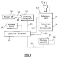
- the anti-theft device 10 shown diagrammatically in FIG. 1 comprises a key, or false, key 10 which is intended to be introduced into the barrel, or false barrel, of an anti-theft switch 12.
- the switch is provided to equip the vehicle dashboard and its design is of a type substantially similar to that of the vehicle start switch according to the prior art.
- the user operates the ignition key 10 or an ignition ring.
- the ignition key 10 is in fact a false key in that it does not necessarily act on a mechanical lock, although such a real key brings an additional degree of security by adding an additional locking or unlocking means in chain with the general design of an electric lock.
- the anti-theft switch 12 comprises a key switch 14 which is intended to detect the absence of the key 10 or the presence in the inserted position of the latter.
- the switch 12 also includes a multi-position control switch 16 for controlling the start of the vehicle engine and for controlling the supply of power to various electrical circuits of the vehicle.
- the key switch 14 is connected by a line 18 to an input of an anti-theft control unit 20 while the control switch 16 is connected by a line 22 to another input of the anti-theft control unit 20.
- the anti-theft control unit includes an analysis circuit which is in particular capable of reading the positions occupied by the switches 14 and 16 of the switch 12.
- the anti-theft control unit comprises for example a microcontroller such as an INTEL 8051. circuit This circuit contains a program for reading the input ports to inform the anti-theft control unit of the positions of the various switches of the switch 12 as will be explained by the following.
- the anti-theft control unit 20 exchanges signals with a interrogation and reception station 24 which exchanges signals by lines 26 and 28 with a badge 30 of keyless access to the vehicle.
- the latter produces on a link 32 a control signal for starting, in one or the other direction, of an anti-theft motor 34 which acts on a member 36 for mechanical locking of the vehicle steering column, or of the gearbox output shaft.
- the central anti-theft device 20 activates a forgetting alarm means 38.
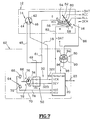
- FIG. 2 A first embodiment of an electric anti-theft device according to the invention will now be described with reference to the diagram in FIG. 2 in which components identical or similar to those in FIG. 1 are designated by the same reference numbers.
- the key switch 14 comprises a tilting movable contact 42 which is permanently connected to the + BAT terminal of the vehicle battery and the free end of which cooperates with a fixed contact 44 in the absence of a key, or with a contact fixed 46 when a key 10 is inserted into the control switch 12.
- the fixed contact 44 is connected by a line 48 to the power input 49 of a power supply block 50 of the motor 34 which receives locking control signals and unlocking by 32V and 32D lines connected to VER, DEV output ports of the anti-theft control unit 20.
- the fixed contact 46 of the key switch 14 is connected by line 18 to a "Request" input port of the anti-theft control unit 20 so that the latter can trigger a sequence for identifying the unlocking request the lock or the lock request.
- the multi-position control switch 16 is a rotary type switch which includes a movable control contact 52 which is permanently connected to the + BAT terminal of the vehicle battery.
- the movable control contact 52 is capable of successively occupying several positions offset angularly with respect to each other and which are marked “0”, “ACC", "M”, and “D” in the figures.
- the rotary movable control contact 52 is capable of cooperating with one or more conductive tracks arranged in an arc forming the fixed contacts of switch 16.
- the movable contact 52 When the movable contact 52 is in the ACC position, it cooperates with a fixed track 54 which is electrically connected to the ACC supply circuit of the vehicle accessories.
- Track 58 is the fixed starter contact DEM of the vehicle combustion engine (not shown) which is connected to the starter in a manner which will be described in more detail below.
- the conductive track 60 constitutes the fixed unlocking contact within the meaning of the invention and the arrangement of the track 60 relative to the track 58 is such that the movable contact 52 is simultaneously in contact with the two tracks 58 and 60, these last ones extending over the same angular sector.
- the unlocking contact 60 is permanently connected to the electrical supply input 49 of the power supply 50 of the motor 34, by a line 61.
- the blocking module 62 will now be described in more detail surrounded by a dashed line at the bottom of FIG. 2.
- the blocking module 62 comprises means 64 for detecting the locked or unlocked state of the anti-theft device which deliver a signal corresponding to the central anti-theft device 20.
- the detection means 64 are constituted by a two-position detection switch.
- the detection switch includes a movable detection contact 66 which is here linked in rotation to the motor 34 for driving the anti-theft blocking member and which is capable of cooperating with a first fixed track-like contact 68 which is connected by a line 70 to an input port H1V of the anti-theft control unit 20, when the anti-theft device is in the locked position.
- the movable detection contact 66 is also capable of cooperating with a second fixed track-shaped contact 72 which is connected, by a line 74 to an input port H2D of the anti-theft control unit 20 when the anti-theft device is in the unlocked position.
- means 80 are also provided for inhibiting the supply of electrical energy to the starter motor DEM.
- the inhibition means 80 consist of an inhibition switch.
- the movable detection contact 66 is permanently connected to the + BAT terminal of the vehicle battery.
- the muting switch 80 comprises a movable muting contact 82 which is permanently connected to the fixed starter contact 58 of the multi-contact switch 16 of the switch 12 by a line 83.
- the movable inhibition contact 82 is capable of moving between a neutral rest position illustrated in FIG. 2 and an active position in which it is in contact with a fixed contact 84 in the form of a track which is connected by a line 86 to the DEM starter.
- the mobile inhibition contact 82 is linked in movement to the mobile detection contact 66 by a mechanical link 88 shown diagrammatically in FIG. 1.
- the mobile inhibition contact 82 is in its neutral position, while it is in its active position in contact with the track.
- the movable detection contact 66 is in contact with the fixed contact 72, that is to say when the anti-theft device is unlocked.
- the mobile contact member 42 is in contact with the fixed contact 46 and it transmits via line 18 an unlocking request request to the "Request" input port of the anti-theft control unit 20.
- the change of state of the key switch 14 also has the effect of interrupting the direct electrical supply by line 48 of the power supply 50 of the motor 34.
- the conductor then pivots the multiple contact switch 16, the movable control element 52 of which can pivot to its maximum angular position in which it is simultaneously in contact with the fixed contacts 56, 58 and 60.
- the coming into contact of the movable element with the fixed unlocking contact 60 causes the supply of electrical energy to the control unit 50 of the motor 34.
- the anti-theft control unit 20 which has previously received an order at its "Request" input port transmits via the line 32V an order to the power supply unit 50 which causes the supply of the drive motor 34 in the direction of unlocking the lock.
- the motor 34 is illustrated halfway between the locking position determined by the mechanical stop 76 and the unlocking position determined by the mechanical unlocking stop 78.
- the mobile detection unit 66 has left the fixed contact 68 and the anti-theft control unit 20 has therefore received a corresponding message via the line 70.
- the movable contact 66 for detection has not yet reached the fixed contact 72 for detecting unlocking and the movable inhibit contact 82 has not yet reached the fixed contact 84.
- the anti-theft device is therefore being unlocked and the starter is still not supplied with electrical energy since the movable inhibition contact 82 has not yet electrically connected line 83 to line 86.
- the mobile detection unit 66 which is in contact with the fixed contact 72 also transmitted a signal corresponding to the input port H2V of the anti-theft control unit 20.
- the mobile inhibition contact 82 has come into contact with the fixed contact 84 and the starter DEM is thus electrically connected to the terminal + BAT by the mobile control contact 52, the fixed starter contact 58, the line 83, the mobile muting contact 82 and the line 86.
- the lock is therefore in the unlocked position and the vehicle's combustion engine starter is powered. electrically to allow the driver to start the vehicle.
- the driver can then return the movable control contact 52 from the start position D to the on position M illustrated in FIG. 4 in which the movable contact 52 is simultaneously in contact with the fixed contact 54 supplying the accessories ACC and with the fixed contact 56 supplying the ALL ignition circuit.
- the driver removes the dummy key 10, which has the effect of bringing the key contact 14 back to its position illustrated in FIGS. 2 and 5 in which the movable contact 42 directly connects the terminal + BAT to the electrical input 49 of the power supply 50 of the motor 34 via the line 48.
- the anti-theft control unit 20 then transmits an unlocking order via the line 32D to the power supply unit 50 and to the motor 34, the latter leaving the unlocking position against the mechanical unlocking stop 78 to go to the locking position. determined by the mechanical stop of locking 76, the various components then returning to their respective positions illustrated in FIG. 2.
- FIGS. 6 to 9 The second embodiment illustrated in FIGS. 6 to 9 will now be described in which components identical or similar to those of FIGS. 1 to 5 are designated by the same reference numbers.
- the detection means 64 consist of two HALL effect sensors 68, 72 which are connected to the input ports H2H and D1V of the anti-theft control unit 20 by the lines 70 and 74.
- the movable contact 66 is here replaced by a movable element 66 which acts on one or the other of the two sensors 68 or 72 depending on the position it occupies with respect to these sensors.
- the inhibition means 80 here consist of an electronic circuit shown schematically in the form of a transistor 90, the collector 92 of which is connected to the terminal + BAT of the battery, whose transmitter 94 is connected to the starter DEM by a line 86 and whose base 96 is connected by a line 98 to an output port of the central anti-theft device 20.
- the anti-theft control unit 20 receives a signal via the line 83 coming from the fixed start contact 58, but the transistor 90 is in the blocked state because its base 96 is not supplied by the anti-theft control unit 20.
- the anti-theft control unit 20 receives from the sensor 72, via the line 74 an unlocking indication signal at its input port H2D.
- the anti-theft control unit 20 After analyzing this unlocking signal, the anti-theft control unit 20 supplies, via the line 98, the base 96 of the transistor 90 and thus causes the starter to be supplied with power. DEM from the input terminal + BAT of the battery through the collector 92 and the transmitter 94.
- the driver brings the movable contact 52 back to its running position, as shown in FIG. 8.
- the anti-theft control unit 20 therefore knows that the anti-theft device is in the unlocked position and that the vehicle is in motion.
- This operation causes a lock request signal which is transmitted by line 18 to the "Request" input port of the anti-theft control unit 20 which controls, by line 32V, the unlocking block 50 to cause the rotation of the motor. 34 to the anti-theft locking position.
- the motor 34 is illustrated in FIG. 9 in an intermediate position halfway between the unlocking and the locking.
- This change of state of the input port causes the control of the transistor 90 to be interrupted and therefore makes it impossible to start the starter from now on.
- the invention is in particular not limited to the production of a key switch 14 in the form of an electric switch controlled by a false key, this function being able to be replaced by any other type of electric switch controlled directly or indirectly. by the driver.
- the multi-position switch 16 is not necessarily a rotary switch.
Landscapes
- Engineering & Computer Science (AREA)
- Mechanical Engineering (AREA)
- Lock And Its Accessories (AREA)
- Auxiliary Drives, Propulsion Controls, And Safety Devices (AREA)
- Hybrid Electric Vehicles (AREA)
Applications Claiming Priority (3)
| Application Number | Priority Date | Filing Date | Title |
|---|---|---|---|
| FR9503395 | 1995-03-21 | ||
| FR9503395A FR2731968B1 (fr) | 1995-03-21 | 1995-03-21 | Antivol electrique, notamment pour un vehicule automobile |
| US08/623,315 US5808543A (en) | 1995-03-21 | 1996-03-26 | Electrical anti-theft security system, especially for a motor vehicle |
Publications (5)
| Publication Number | Publication Date |
|---|---|
| EP0733524A1 true EP0733524A1 (de) | 1996-09-25 |
| EP0733524A2 EP0733524A2 (de) | 1996-09-25 |
| EP0733524A8 EP0733524A8 (de) | 2001-04-04 |
| EP0733524A3 EP0733524A3 (de) | 2001-04-11 |
| EP0733524B1 EP0733524B1 (de) | 2002-02-27 |
Family
ID=26231831
Family Applications (1)
| Application Number | Title | Priority Date | Filing Date |
|---|---|---|---|
| EP19960400556 Expired - Lifetime EP0733524B1 (de) | 1995-03-21 | 1996-03-18 | Elektrische Diebstahlsicherung, insbesondere für ein Kraftfahrzeug |
Country Status (5)
| Country | Link |
|---|---|
| US (1) | US5808543A (de) |
| EP (1) | EP0733524B1 (de) |
| DE (1) | DE69619413T2 (de) |
| ES (1) | ES2172643T3 (de) |
| FR (1) | FR2731968B1 (de) |
Cited By (3)
| Publication number | Priority date | Publication date | Assignee | Title |
|---|---|---|---|---|
| WO2002012032A3 (de) * | 2000-08-10 | 2003-12-18 | Daimler Chrysler Ag | Elektronische starter- und lenkungsverriegelungsvorrichtung für ein kraftfahrzeug |
| DE19916966C5 (de) * | 1999-04-15 | 2006-09-21 | Daimlerchrysler Ag | Elektronische Zündstartschalter- und Lenkradverriegelungsvorrichtung |
| CN103264679A (zh) * | 2013-05-24 | 2013-08-28 | 无锡伊佩克科技有限公司 | 一种汽车防盗系统 |
Families Citing this family (7)
| Publication number | Priority date | Publication date | Assignee | Title |
|---|---|---|---|---|
| FR2805229B1 (fr) | 2000-02-18 | 2002-04-12 | Valeo Electronique | Agencement de securite pour vehicule automobile equipe d'un systeme programme de controle, et en particulier d'un systeme de controle dit "mains libres" |
| DE10010450C2 (de) * | 2000-03-03 | 2002-04-25 | Audi Ag | Fahrzeugverriegelungsvorrichtung |
| US6516640B2 (en) | 2000-12-05 | 2003-02-11 | Strattec Security Corporation | Steering column lock apparatus and method |
| US6571587B2 (en) | 2001-01-09 | 2003-06-03 | Strattec Security Corporation | Steering column lock apparatus and method |
| US7173348B2 (en) * | 2003-03-03 | 2007-02-06 | Startech Automotive Anti Theft Systems Ltd. | Device, system and method for preventing vehicle theft |
| US7140213B2 (en) * | 2004-02-21 | 2006-11-28 | Strattec Security Corporation | Steering column lock apparatus and method |
| US7757803B2 (en) | 2006-07-14 | 2010-07-20 | Richard Fiske | Motor vehicle operator identification and maximum speed limiter |
Citations (2)
| Publication number | Priority date | Publication date | Assignee | Title |
|---|---|---|---|---|
| US3735833A (en) * | 1971-10-12 | 1973-05-29 | J Meple Height Sutkowski | Theft prevention device for motor vehicles |
| US5202580A (en) * | 1990-11-01 | 1993-04-13 | Briggs & Stratton | Anti-tampering magnet for automobile ignition lock |
Family Cites Families (11)
| Publication number | Priority date | Publication date | Assignee | Title |
|---|---|---|---|---|
| DE836750C (de) * | 1949-08-10 | 1952-04-17 | Dr Alfred Hettich | Sicherheitsschloss an Kraftfahrzeugen |
| US3827526A (en) * | 1973-02-05 | 1974-08-06 | Wagner Electric Corp | Automotive security system and solenoid lock for same |
| JPS54153442A (en) * | 1978-05-22 | 1979-12-03 | Nissan Motor Co Ltd | Steering lock apparatus |
| US4471852A (en) * | 1982-02-08 | 1984-09-18 | Ike Schield | Anti-theft devices for automotive vehicles |
| US5132661A (en) * | 1987-10-02 | 1992-07-21 | Universal Photonix, Inc. | Security system employing optical key shape reader |
| IL96262A (en) * | 1990-11-06 | 1994-02-27 | Mul T Lock Ltd | Vehicle anti-theft system |
| US5554966A (en) * | 1992-01-20 | 1996-09-10 | Pioneer Electronic Corporation | Car-stereo with removable control panel, alarm, and power conservation |
| US5451925A (en) * | 1992-04-09 | 1995-09-19 | Le; Hy D. | Passive instant automatic vehicle anti-theft device |
| FR2710599B1 (fr) * | 1993-09-30 | 1995-11-24 | Valeo Securite Habitacle | Procédé de contrôle d'un organe antivol de véhicule avec système d'accès par commande à distance, et organe antivol ainsi constitué. |
| JP3001782B2 (ja) * | 1994-09-28 | 2000-01-24 | 本田技研工業株式会社 | 車両盗難防止対応エンジン制御装置 |
| FR2731965B1 (fr) * | 1995-03-21 | 1997-04-25 | Valeo Securite Habitacle | Antivol electrique |
-
1995
- 1995-03-21 FR FR9503395A patent/FR2731968B1/fr not_active Expired - Fee Related
-
1996
- 1996-03-18 EP EP19960400556 patent/EP0733524B1/de not_active Expired - Lifetime
- 1996-03-18 DE DE69619413T patent/DE69619413T2/de not_active Expired - Fee Related
- 1996-03-18 ES ES96400556T patent/ES2172643T3/es not_active Expired - Lifetime
- 1996-03-26 US US08/623,315 patent/US5808543A/en not_active Expired - Fee Related
Patent Citations (2)
| Publication number | Priority date | Publication date | Assignee | Title |
|---|---|---|---|---|
| US3735833A (en) * | 1971-10-12 | 1973-05-29 | J Meple Height Sutkowski | Theft prevention device for motor vehicles |
| US5202580A (en) * | 1990-11-01 | 1993-04-13 | Briggs & Stratton | Anti-tampering magnet for automobile ignition lock |
Non-Patent Citations (1)
| Title |
|---|
| SCHNEIDER C ET AL: "EIN FAHRZEUGSICHERUNGSSYSTEM OHNE MECHANISCHEN SCHLUESSEL VEHICLE SECURITY SYSTEM DISPENSING WITH MECHANICAL KEY", ATZ AUTOMOBILTECHNISCHE ZEITSCHRIFT,DE,FRANCKH'SCHE VERLAGSHANDLUNG. STUTTGART, vol. 96, no. 5, 1 May 1994 (1994-05-01), pages 321 - 323,330, XP000442154, ISSN: 0001-2785 * |
Cited By (4)
| Publication number | Priority date | Publication date | Assignee | Title |
|---|---|---|---|---|
| DE19916966C5 (de) * | 1999-04-15 | 2006-09-21 | Daimlerchrysler Ag | Elektronische Zündstartschalter- und Lenkradverriegelungsvorrichtung |
| WO2002012032A3 (de) * | 2000-08-10 | 2003-12-18 | Daimler Chrysler Ag | Elektronische starter- und lenkungsverriegelungsvorrichtung für ein kraftfahrzeug |
| US6914347B2 (en) | 2000-08-10 | 2005-07-05 | Daimlerchrysler Ag | Electronic starter and steering lock device for a motor vehicle |
| CN103264679A (zh) * | 2013-05-24 | 2013-08-28 | 无锡伊佩克科技有限公司 | 一种汽车防盗系统 |
Also Published As
| Publication number | Publication date |
|---|---|
| FR2731968A1 (fr) | 1996-09-27 |
| ES2172643T3 (es) | 2002-10-01 |
| US5808543A (en) | 1998-09-15 |
| EP0733524A8 (de) | 2001-04-04 |
| EP0733524B1 (de) | 2002-02-27 |
| DE69619413D1 (de) | 2002-04-04 |
| EP0733524A3 (de) | 2001-04-11 |
| DE69619413T2 (de) | 2002-11-14 |
| FR2731968B1 (fr) | 1997-04-30 |
Similar Documents
| Publication | Publication Date | Title |
|---|---|---|
| EP0733521B1 (de) | Elektrische Diebstahlsicherung | |
| EP1335330B1 (de) | Entriegelungssystem einer Kraftfahrzeugöffnung | |
| FR2740414A1 (fr) | Systeme de communication prevu entre une cle de contact et un vehicule et protege contre les fausses manoeuvres | |
| FR2589930A1 (fr) | Systeme de verrouillage pour voiture, commande par un signal radio | |
| FR2837766A1 (fr) | Appareil de commande de demarrage du moteur thermique d'un vehicule | |
| EP0733524B1 (de) | Elektrische Diebstahlsicherung, insbesondere für ein Kraftfahrzeug | |
| FR2715353A1 (fr) | Dispositif de sélection pour appareil de commande automatique d'une boîte de vitesses d'automobile. | |
| WO2014095914A1 (fr) | Procédé de contrôle à distance d'un système de contrôle de manoeuvre(s) d'un véhicule par un boîtier de commande | |
| EP0733526B1 (de) | Verbesserte Diebstahlsicherung, insbesondere für ein Kraftfahrzeug | |
| EP2311715B1 (de) | Vorrichtung und Verfahren zur automatischen Verriegelung einer Lenksäule | |
| EP0761515B1 (de) | Diebstahlschutzsystem für ein Kraftfahrzeug | |
| EP0733522B1 (de) | Elektrische Diebstahlsicherung für ein Kraftfahrzeug | |
| FR2801334A1 (fr) | Systeme de verrouillage electronique | |
| EP1153812B1 (de) | Elektrische Diebstahlsicherung, insbesondere für ein Kraftfahrzeug | |
| WO2019106300A1 (fr) | Procédé d'activation d'au moins une fonction d'un équipement d'un véhicule | |
| FR2873654A1 (fr) | Bicyclette equipee d'un dispositif antivol | |
| EP0733525B1 (de) | Verbesserte Diebstahlsicherung, insbesondere für ein Kraftfahrzeug | |
| EP0646506B1 (de) | Diebstahlschutzvorrichtung sowie Verfahren zu deren Steuerung für Kraftfahrzeuge mit fernsteuerbarer Verriegelung | |
| FR2695604A1 (fr) | Dispositif antivol pour tout véhicule muni d'un organe de direction comportant un arbre rotatif transmettant la commande. | |
| EP1169213B1 (de) | Diebstahlsicherung für motorrad | |
| FR2750097A1 (fr) | Antivol de vehicule automobile a organe apte a agir a distance sur un circuit electrique et vehicule automobile le comportant | |
| EP0596762A1 (de) | Lenkdiebstahl-Schutzvorrichtung für Kraftfahrzeuge und Schlüssel für derartige Vorrichtung | |
| FR2764927A1 (fr) | Ensemble de verrouillage / deverrouillage, a distance, des portieres d'un vehicule |
Legal Events
| Date | Code | Title | Description |
|---|---|---|---|
| PUAI | Public reference made under article 153(3) epc to a published international application that has entered the european phase |
Free format text: ORIGINAL CODE: 0009012 |
|
| AK | Designated contracting states |
Kind code of ref document: A1 Designated state(s): DE ES GB IT |
|
| 17P | Request for examination filed |
Effective date: 19970321 |
|
| 17Q | First examination report despatched |
Effective date: 19991124 |
|
| PUAB | Information related to the publication of an a document modified or deleted |
Free format text: ORIGINAL CODE: 0009199EPPU |
|
| PUAF | Information related to the publication of a search report (a3 document) modified or deleted |
Free format text: ORIGINAL CODE: 0009199SEPU |
|
| PUAL | Search report despatched |
Free format text: ORIGINAL CODE: 0009013 |
|
| GRAG | Despatch of communication of intention to grant |
Free format text: ORIGINAL CODE: EPIDOS AGRA |
|
| D17D | Deferred search report published (deleted) | ||
| AK | Designated contracting states |
Kind code of ref document: A3 Designated state(s): DE ES GB IT |
|
| GRAG | Despatch of communication of intention to grant |
Free format text: ORIGINAL CODE: EPIDOS AGRA |
|
| GRAH | Despatch of communication of intention to grant a patent |
Free format text: ORIGINAL CODE: EPIDOS IGRA |
|
| GRAH | Despatch of communication of intention to grant a patent |
Free format text: ORIGINAL CODE: EPIDOS IGRA |
|
| REG | Reference to a national code |
Ref country code: GB Ref legal event code: IF02 |
|
| GRAA | (expected) grant |
Free format text: ORIGINAL CODE: 0009210 |
|
| AK | Designated contracting states |
Kind code of ref document: B1 Designated state(s): DE ES GB IT |
|
| REF | Corresponds to: |
Ref document number: 69619413 Country of ref document: DE Date of ref document: 20020404 |
|
| GBT | Gb: translation of ep patent filed (gb section 77(6)(a)/1977) |
Effective date: 20020422 |
|
| REG | Reference to a national code |
Ref country code: ES Ref legal event code: FG2A Ref document number: 2172643 Country of ref document: ES Kind code of ref document: T3 |
|
| PLBE | No opposition filed within time limit |
Free format text: ORIGINAL CODE: 0009261 |
|
| STAA | Information on the status of an ep patent application or granted ep patent |
Free format text: STATUS: NO OPPOSITION FILED WITHIN TIME LIMIT |
|
| 26N | No opposition filed |
Effective date: 20021128 |
|
| PGFP | Annual fee paid to national office [announced via postgrant information from national office to epo] |
Ref country code: GB Payment date: 20050304 Year of fee payment: 10 |
|
| PGFP | Annual fee paid to national office [announced via postgrant information from national office to epo] |
Ref country code: DE Payment date: 20050308 Year of fee payment: 10 |
|
| PGFP | Annual fee paid to national office [announced via postgrant information from national office to epo] |
Ref country code: ES Payment date: 20050317 Year of fee payment: 10 |
|
| PG25 | Lapsed in a contracting state [announced via postgrant information from national office to epo] |
Ref country code: GB Free format text: LAPSE BECAUSE OF NON-PAYMENT OF DUE FEES Effective date: 20060318 |
|
| PG25 | Lapsed in a contracting state [announced via postgrant information from national office to epo] |
Ref country code: ES Free format text: LAPSE BECAUSE OF NON-PAYMENT OF DUE FEES Effective date: 20060321 |
|
| PGFP | Annual fee paid to national office [announced via postgrant information from national office to epo] |
Ref country code: IT Payment date: 20060331 Year of fee payment: 11 |
|
| PG25 | Lapsed in a contracting state [announced via postgrant information from national office to epo] |
Ref country code: DE Free format text: LAPSE BECAUSE OF NON-PAYMENT OF DUE FEES Effective date: 20061003 |
|
| GBPC | Gb: european patent ceased through non-payment of renewal fee |
Effective date: 20060318 |
|
| REG | Reference to a national code |
Ref country code: ES Ref legal event code: FD2A Effective date: 20060321 |
|
| PG25 | Lapsed in a contracting state [announced via postgrant information from national office to epo] |
Ref country code: IT Free format text: LAPSE BECAUSE OF NON-PAYMENT OF DUE FEES Effective date: 20070318 |