EP0733536B1 - Elektrische Servolenkung - Google Patents
Elektrische Servolenkung Download PDFInfo
- Publication number
- EP0733536B1 EP0733536B1 EP96301928A EP96301928A EP0733536B1 EP 0733536 B1 EP0733536 B1 EP 0733536B1 EP 96301928 A EP96301928 A EP 96301928A EP 96301928 A EP96301928 A EP 96301928A EP 0733536 B1 EP0733536 B1 EP 0733536B1
- Authority
- EP
- European Patent Office
- Prior art keywords
- motor
- control circuit
- end frame
- electric power
- housing
- Prior art date
- Legal status (The legal status is an assumption and is not a legal conclusion. Google has not performed a legal analysis and makes no representation as to the accuracy of the status listed.)
- Expired - Lifetime
Links
- 230000007246 mechanism Effects 0.000 claims description 19
- 239000000463 material Substances 0.000 claims description 6
- 239000011248 coating agent Substances 0.000 claims description 4
- 238000000576 coating method Methods 0.000 claims description 4
- 238000009413 insulation Methods 0.000 claims description 4
- 229910052751 metal Inorganic materials 0.000 claims description 4
- 239000002184 metal Substances 0.000 claims description 4
- 238000007789 sealing Methods 0.000 claims description 4
- 230000007423 decrease Effects 0.000 description 6
- 230000003247 decreasing effect Effects 0.000 description 6
- 229910052782 aluminium Inorganic materials 0.000 description 5
- XAGFODPZIPBFFR-UHFFFAOYSA-N aluminium Chemical compound [Al] XAGFODPZIPBFFR-UHFFFAOYSA-N 0.000 description 5
- 239000000470 constituent Substances 0.000 description 5
- 230000009467 reduction Effects 0.000 description 5
- 239000000758 substrate Substances 0.000 description 5
- 239000003990 capacitor Substances 0.000 description 4
- 238000010586 diagram Methods 0.000 description 4
- 230000005389 magnetism Effects 0.000 description 4
- 230000007935 neutral effect Effects 0.000 description 4
- 230000002950 deficient Effects 0.000 description 3
- 230000002093 peripheral effect Effects 0.000 description 3
- XLYOFNOQVPJJNP-UHFFFAOYSA-N water Substances O XLYOFNOQVPJJNP-UHFFFAOYSA-N 0.000 description 3
- RYGMFSIKBFXOCR-UHFFFAOYSA-N Copper Chemical compound [Cu] RYGMFSIKBFXOCR-UHFFFAOYSA-N 0.000 description 2
- 230000002159 abnormal effect Effects 0.000 description 2
- 229910052802 copper Inorganic materials 0.000 description 2
- 239000010949 copper Substances 0.000 description 2
- 238000001514 detection method Methods 0.000 description 2
- 230000000694 effects Effects 0.000 description 2
- 239000012212 insulator Substances 0.000 description 2
- 239000000696 magnetic material Substances 0.000 description 2
- 229910000831 Steel Inorganic materials 0.000 description 1
- 230000008859 change Effects 0.000 description 1
- 230000007613 environmental effect Effects 0.000 description 1
- 230000002349 favourable effect Effects 0.000 description 1
- 230000004907 flux Effects 0.000 description 1
- 239000004519 grease Substances 0.000 description 1
- 238000000465 moulding Methods 0.000 description 1
- 238000013021 overheating Methods 0.000 description 1
- 230000005855 radiation Effects 0.000 description 1
- 239000011347 resin Substances 0.000 description 1
- 229920005989 resin Polymers 0.000 description 1
- 230000004044 response Effects 0.000 description 1
- 230000000630 rising effect Effects 0.000 description 1
- 230000008054 signal transmission Effects 0.000 description 1
- 238000000638 solvent extraction Methods 0.000 description 1
- 239000010959 steel Substances 0.000 description 1
- 238000004804 winding Methods 0.000 description 1
Images



Classifications
-
- B—PERFORMING OPERATIONS; TRANSPORTING
- B62—LAND VEHICLES FOR TRAVELLING OTHERWISE THAN ON RAILS
- B62D—MOTOR VEHICLES; TRAILERS
- B62D5/00—Power-assisted or power-driven steering
- B62D5/04—Power-assisted or power-driven steering electrical, e.g. using an electric servo-motor connected to, or forming part of, the steering gear
- B62D5/0403—Power-assisted or power-driven steering electrical, e.g. using an electric servo-motor connected to, or forming part of, the steering gear characterised by constructional features, e.g. common housing for motor and gear box
- B62D5/0406—Power-assisted or power-driven steering electrical, e.g. using an electric servo-motor connected to, or forming part of, the steering gear characterised by constructional features, e.g. common housing for motor and gear box including housing for electronic control unit
-
- H—ELECTRICITY
- H01—ELECTRIC ELEMENTS
- H01R—ELECTRICALLY-CONDUCTIVE CONNECTIONS; STRUCTURAL ASSOCIATIONS OF A PLURALITY OF MUTUALLY-INSULATED ELECTRICAL CONNECTING ELEMENTS; COUPLING DEVICES; CURRENT COLLECTORS
- H01R39/00—Rotary current collectors, distributors or interrupters
- H01R39/02—Details for dynamo electric machines
- H01R39/38—Brush holders
- H01R39/385—Means for mechanical fixation of the brush holder
-
- H—ELECTRICITY
- H02—GENERATION; CONVERSION OR DISTRIBUTION OF ELECTRIC POWER
- H02K—DYNAMO-ELECTRIC MACHINES
- H02K11/00—Structural association of dynamo-electric machines with electric components or with devices for shielding, monitoring or protection
- H02K11/30—Structural association with control circuits or drive circuits
- H02K11/33—Drive circuits, e.g. power electronics
-
- H—ELECTRICITY
- H02—GENERATION; CONVERSION OR DISTRIBUTION OF ELECTRIC POWER
- H02K—DYNAMO-ELECTRIC MACHINES
- H02K23/00—DC commutator motors or generators having mechanical commutator; Universal AC/DC commutator motors
- H02K23/66—Structural association with auxiliary electric devices influencing the characteristic of, or controlling, the machine, e.g. with impedances or switches
-
- H—ELECTRICITY
- H02—GENERATION; CONVERSION OR DISTRIBUTION OF ELECTRIC POWER
- H02K—DYNAMO-ELECTRIC MACHINES
- H02K5/00—Casings; Enclosures; Supports
- H02K5/04—Casings or enclosures characterised by the shape, form or construction thereof
- H02K5/14—Means for supporting or protecting brushes or brush holders
- H02K5/143—Means for supporting or protecting brushes or brush holders for cooperation with commutators
- H02K5/148—Slidably supported brushes
-
- H—ELECTRICITY
- H02—GENERATION; CONVERSION OR DISTRIBUTION OF ELECTRIC POWER
- H02K—DYNAMO-ELECTRIC MACHINES
- H02K7/00—Arrangements for handling mechanical energy structurally associated with dynamo-electric machines, e.g. structural association with mechanical driving motors or auxiliary dynamo-electric machines
- H02K7/10—Structural association with clutches, brakes, gears, pulleys or mechanical starters
- H02K7/108—Structural association with clutches, brakes, gears, pulleys or mechanical starters with friction clutches
- H02K7/1085—Magnetically influenced friction clutches
-
- H—ELECTRICITY
- H02—GENERATION; CONVERSION OR DISTRIBUTION OF ELECTRIC POWER
- H02K—DYNAMO-ELECTRIC MACHINES
- H02K5/00—Casings; Enclosures; Supports
- H02K5/04—Casings or enclosures characterised by the shape, form or construction thereof
- H02K5/22—Auxiliary parts of casings not covered by groups H02K5/06-H02K5/20, e.g. shaped to form connection boxes or terminal boxes
- H02K5/225—Terminal boxes or connection arrangements
-
- H—ELECTRICITY
- H02—GENERATION; CONVERSION OR DISTRIBUTION OF ELECTRIC POWER
- H02K—DYNAMO-ELECTRIC MACHINES
- H02K9/00—Arrangements for cooling or ventilating
- H02K9/28—Cooling of commutators, slip-rings or brushes e.g. by ventilating
Definitions
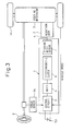
- the EPS is mounted to a vehicle at a lower position in the engine room, and is exposed to undesirable environmental conditions so that it is submerged in the water depending upon the running speed even though the depth of water may be small and it is subjected to muddy water and snow adhered thereto. Therefore, the control circuit of the EPS is usually arranged inside the passenger compartment where the environment is favorable.
- the motor and the control circuit with the motor housing are arranged in thermal contact with the rack housing.
- the rack housing is preferably made of aluminum and has a large thermal capacity and a small heat resistance. Therefore, the rack housing suitably absorbs heat transmitted from the motor housing, so that heat generated by the motor and the control circuit is efficiently radiated through the motor housing to the rack housing and the temperature in the motor housing is maintained relatively low. Accordingly, the stable operation of the electric power steering device is guaranteed.
- the motor housing comprises an end frame having the motor and the control circuit assembled thereonto, and a cup-shaped motor case covering the motor and the control circuit and hermetically coupled to the end frame, the end frame being fixed to the rack housing.
- the whole motor housing is of a water-proof structure, and the connector for connection to external units can be hermetically passed through the motor case without impairing waterproof characteristics.
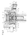
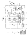
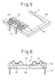
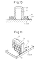
- a motor wiring connecting the control circuit 9 (switching elements 33) to the motor 5 (brushes 22) is realized by using connection terminals 43 provided on the control circuit 9. That is, pigtails 44 (see Figs. 2 and 8) leading from the brushes 22 are usually made of a copper mesh wire to provide lower resistance, and on the other hand, the connection of the switching elements 33 is carried out by bonding wires 45.
- the brushes 22 and the switching elements 33 are coupled in a different manner.
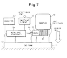
- this embodiment employs the layout structure shown in Fig. 1 in order to obtain good heat-radiating performance without impairing functions of the constituent parts.
Landscapes
- Engineering & Computer Science (AREA)
- Power Engineering (AREA)
- Chemical & Material Sciences (AREA)
- Combustion & Propulsion (AREA)
- Transportation (AREA)
- Mechanical Engineering (AREA)
- Microelectronics & Electronic Packaging (AREA)
- Power Steering Mechanism (AREA)
- Motor Or Generator Current Collectors (AREA)
- Motor Or Generator Cooling System (AREA)
Claims (9)
- Elektrolenkvorrichtung für ein Kraftfahrzeug mit einem Lenksystem mit einem Lenkgetriebe, welches in einem Zahnstangengehäuse untergebracht ist, wobei die Elektrolenkvorrichtung umfaßt:dadurch gekennzeichnet, daß:eine Ausgangswelle (4), welche mit dem Lenkgetriebe (3) verbunden ist;einen Motor (5) zur Drehmomentunterstützung des Lenkgetriebes (3) über die Ausgangswelle (4);eine Steuerschaltung (9) zum Steuern des Motors (5); undein Motorgehäuse (10) zum darin Aufnehmen des Motors (5), wobei das Motorgehäuse (10) in Wärmekontakt mit dem Zahnstangengehäuse 13 angeordnet ist;das Motorgehäuse (10) ferner darin die Steuerschaltung (9) aufnimmt;das Motorgehäuse (10) an dem Zahnstangengehäuse (13) befestigt ist; undder Motor (5) und die Steuerschaltung (9) über das Motorgehäuse (10) in Wärmekontakt mit dem Zahnstangengehäuse (13) sind.
- Elektrolenkvorrichtung nach Anspruch 1, wobei das Motorgehäuse (10) einen Endrahmen (11) mit dem Motor (5) und der Steuerschaltung (139, welche daran montiert sind, und einen tellerförmigen Motorbehälter (12) umfaßt, welcher den Motor (5) und die Steuerschaltung (9) abdeckt und hermetisch mit dem Endrahmen (11) verbunden ist, wobei der Endrahmen (11) an dem Zahnstangengehäuse (13) befestigt ist.
- Elektrolenkvorrichtung nach Anspruch 2, wobei ein Beschichtungsmaterial mit einem niedrigen Wärmewiderstand und guten Dichtungseigenschaften zwischen angrenzenden Flächen des Endrahmens (11) und des Zahnstangengehäuses (13) aufgebracht ist.
- Elektrolenkvorrichtung nach Anspruch 2, wobei der Endrahmen (11) einstückig mit einer dünnen Wärmestrahlungsplatte (11b) ausgestattet ist und die Steuerschaltung (9) derart angeordnet ist, daß sie in Wärmekontakt mit der Wärmestrahlungsplatte (11b) ist.
- Elektrolenkvorrichtung nach Anspruch 2, wobei eine Verbindungsvorrichtung (16) sich hermetisch durch das Motorgehäuse (10) für einen externen Anschluß erstreckt.
- Elektrolenkvorrichtung nach Anspruch 2, wobei der Motor (5) eine drehbare Welle (20) und einen Kommutator (21) an einem Ende der Welle (20) zum Liefern eines Strom über eine Bürste (22) aufweist.
- Elektrolenkvorrichtung nach Anspruch 6, wobei die Bürste (22) auf der gegenüberliegenden Seite der Steuerschaltung (9) von dem Kommutator (21) angeordnet ist.
- Elektrolenkvorrichtung nach Anspruch 6, wobei die Steuerschaltung (9) Verbindungsanschlüsse (43) aufweist, welche an einem einstückig mit der Verbindungsvorrichtung ausgebildeten Isolierelement angebracht sind, wobei die Verbindungsanschlüsse (43) mit Schaltelementen (33) zum Steuern des Motorstroms über Verbindungsdrähte (45) und mit einem Bürstenanschlußkabel (44) der Bürsten (22) verbunden sind.
- Elektrolenkvorrichtung nach Anspruch 6, wobei eine Bürstenhaltevorrichtung (23) zum Halten der Bürsten (22) aus einem Material (11a) mit guter Wärmeleitfähigkeit besteht und an dem Endrahmen (11) bzw. einem Metallelement (25) befestigt ist, welches über ein Isolierelement mit niedrigem Wärmewiderstand in Wärmekontakt mit dem Endrahmen (11) gebracht ist.
Applications Claiming Priority (3)
| Application Number | Priority Date | Filing Date | Title |
|---|---|---|---|
| JP6636795 | 1995-03-24 | ||
| JP66367/95 | 1995-03-24 | ||
| JP06636795A JP3538944B2 (ja) | 1995-03-24 | 1995-03-24 | 電動式パワーステアリング装置 |
Publications (3)
| Publication Number | Publication Date |
|---|---|
| EP0733536A2 EP0733536A2 (de) | 1996-09-25 |
| EP0733536A3 EP0733536A3 (de) | 1996-11-06 |
| EP0733536B1 true EP0733536B1 (de) | 2000-06-14 |
Family
ID=13313811
Family Applications (1)
| Application Number | Title | Priority Date | Filing Date |
|---|---|---|---|
| EP96301928A Expired - Lifetime EP0733536B1 (de) | 1995-03-24 | 1996-03-21 | Elektrische Servolenkung |
Country Status (3)
| Country | Link |
|---|---|
| US (1) | US5810111A (de) |
| EP (1) | EP0733536B1 (de) |
| JP (1) | JP3538944B2 (de) |
Families Citing this family (56)
| Publication number | Priority date | Publication date | Assignee | Title |
|---|---|---|---|---|
| GB2295590B (en) * | 1994-11-30 | 1999-01-20 | Nsk Ltd | Electric power steering apparatus |
| JP3622362B2 (ja) * | 1996-09-19 | 2005-02-23 | 株式会社デンソー | 電動式パワーステアリング装置 |
| JPH1134891A (ja) * | 1997-07-24 | 1999-02-09 | Mitsuba Corp | 電気式動力操舵装置 |
| ES2196938B1 (es) * | 1997-10-01 | 2005-02-01 | Kayaba Kogyo Kabushiki Kaisha | Motor electrico para sistema electrico de direccion asistida. |
| JPH11115775A (ja) * | 1997-10-20 | 1999-04-27 | Mitsubishi Electric Corp | 電動式パワーステアリング制御装置 |
| US6123167A (en) * | 1998-06-11 | 2000-09-26 | Trw Inc. | Electric steering motor with one-piece metal shell |
| JP2000224822A (ja) * | 1998-06-29 | 2000-08-11 | Mitsubishi Electric Corp | 電動パワーステアリング装置用モータ |
| US6338016B1 (en) * | 1999-03-08 | 2002-01-08 | Trw Inc. | Method and apparatus for detecting a motor stall condition in an electric assist steering system |
| JP3559193B2 (ja) * | 1999-04-30 | 2004-08-25 | 三菱電機株式会社 | 整流子モータ |
| JP3715136B2 (ja) * | 1999-06-03 | 2005-11-09 | トヨタ自動車株式会社 | 電動パワーステアリング装置 |
| US6257364B1 (en) * | 2000-01-20 | 2001-07-10 | Ford Global Technologies, Inc. | Submersible electro-hydraulic powerpack for underhood automotive steering applications |
| JP2001268856A (ja) | 2000-03-22 | 2001-09-28 | Asmo Co Ltd | モータ |
| FR2808937B1 (fr) * | 2000-05-11 | 2002-07-19 | Valeo Systemes Dessuyage | Machine electrique tournante |
| JP3843202B2 (ja) * | 2000-06-02 | 2006-11-08 | 株式会社ジェイテクト | 電動パワーステアリング装置 |
| JP3544347B2 (ja) | 2000-08-29 | 2004-07-21 | 三菱電機株式会社 | 回転電機のブラシホルダ装置 |
| JP4618474B2 (ja) * | 2001-04-16 | 2011-01-26 | 株式会社ジェイテクト | 電動パワーステアリング装置 |
| JP4019408B2 (ja) * | 2001-07-10 | 2007-12-12 | オムロン株式会社 | コントロールユニット |
| JP3593102B2 (ja) | 2002-01-08 | 2004-11-24 | 三菱電機株式会社 | 電動パワーステアリング装置 |
| JP3638269B2 (ja) * | 2002-03-14 | 2005-04-13 | 三菱電機株式会社 | 電動式パワーステアリング装置 |
| US6851509B2 (en) | 2002-08-09 | 2005-02-08 | Denso Corporation | Easy-to-assemble structure of electric power steering device |
| JP4145163B2 (ja) * | 2003-02-21 | 2008-09-03 | 株式会社ショーワ | 電動パワーステアリング装置 |
| JP4279582B2 (ja) * | 2003-03-26 | 2009-06-17 | 株式会社ショーワ | 電動モータ |
| US7600913B2 (en) * | 2003-04-15 | 2009-10-13 | Tedrive Holding B.V. | Saturated transistor based temperature sensor |
| WO2004110848A1 (ja) * | 2003-06-11 | 2004-12-23 | Nsk Ltd. | 電動パワーステアリング装置 |
| KR100554540B1 (ko) * | 2003-12-01 | 2006-03-03 | 현대모비스 주식회사 | 조향컬럼의 틸트 위치를 고려한 전자제어 파워 스티어링 |
| JP4474341B2 (ja) | 2005-07-26 | 2010-06-02 | 日立オートモティブシステムズ株式会社 | 電動パワーステアリング装置 |
| KR100646404B1 (ko) | 2005-10-26 | 2006-11-14 | 주식회사 만도 | 전자 제어 장치 및 이를 구비한 자동차의 전기식 동력 보조조향장치 |
| WO2007119757A1 (ja) * | 2006-04-11 | 2007-10-25 | Nsk Ltd. | 電動パワーステアリング装置及びその組付方法 |
| JP2007318973A (ja) * | 2006-05-29 | 2007-12-06 | Jtekt Corp | モータ及び電動パワーステアリング装置 |
| JP2008004364A (ja) * | 2006-06-22 | 2008-01-10 | Omron Corp | 電子機器、電子機器の製造方法 |
| US8151428B2 (en) * | 2006-08-01 | 2012-04-10 | General Electric Company | Method and apparatus for controlling a mode shifter in a washing machine from a motor controller |
| DE102007013172A1 (de) * | 2007-03-20 | 2008-09-25 | Gebrüder Frei GbmH & Co. KG | Lenkantriebssystem |
| US8046855B2 (en) * | 2007-08-07 | 2011-11-01 | General Electric Company | Method and apparatus for providing redundancy in monitoring the lid switch and basket of a washing machine |
| KR101385926B1 (ko) * | 2007-10-15 | 2014-04-15 | 현대모비스 주식회사 | 전기 조향장치용 모터 앗세이 |
| JP2009119957A (ja) * | 2007-11-13 | 2009-06-04 | Mitsubishi Electric Corp | 電子制御装置および電子制御装置の製造方法 |
| JP5397652B2 (ja) | 2008-02-12 | 2014-01-22 | 株式会社ジェイテクト | 車両用操舵装置 |
| JP5397658B2 (ja) * | 2008-02-12 | 2014-01-22 | 株式会社ジェイテクト | 車両用操舵装置及びそのサブアセンブリの移送方法 |
| JP5397663B2 (ja) * | 2008-07-15 | 2014-01-22 | 株式会社ジェイテクト | 車両用操舵装置 |
| US8708089B2 (en) | 2008-07-15 | 2014-04-29 | Jtekt Corporation | Vehicle steering apparatus |
| JP5084783B2 (ja) * | 2009-05-21 | 2012-11-28 | 三菱電機株式会社 | 電動式パワーステアリング装置 |
| JP2010280245A (ja) * | 2009-06-02 | 2010-12-16 | Jtekt Corp | 車両用操舵装置 |
| EP2574521B1 (de) * | 2010-12-07 | 2016-11-16 | NSK Ltd. | Elektrische servolenkvorrichtung |
| JP5338804B2 (ja) * | 2010-12-28 | 2013-11-13 | 株式会社デンソー | 駆動装置、および、これを用いた電動パワーステアリング装置 |
| JP5725343B2 (ja) | 2011-05-11 | 2015-05-27 | 株式会社デンソー | 駆動装置 |
| GB2503671B (en) * | 2012-07-03 | 2014-12-17 | Dyson Technology Ltd | Control of a brushless motor |
| GB2503670B (en) | 2012-07-03 | 2014-12-10 | Dyson Technology Ltd | Method of preheating a brushless motor |
| JP5660400B2 (ja) * | 2012-08-03 | 2015-01-28 | 株式会社デンソー | 回転電機、および、これを用いた電動パワーステアリング装置 |
| EP2961055A4 (de) * | 2013-02-20 | 2016-05-11 | Nissan Motor | Motor mit wechselrichter |
| US20150042204A1 (en) | 2013-08-09 | 2015-02-12 | Black & Decker Inc. | Brush assembly for an electric motor |
| US9991770B2 (en) | 2013-08-09 | 2018-06-05 | Black & Decker Inc. | Spring post for brush card for a power tool |
| US9866078B2 (en) | 2014-01-29 | 2018-01-09 | Black & Decker Inc. | Brush assembly mount |
| WO2015078459A2 (de) * | 2013-11-26 | 2015-06-04 | Schaeffler Technologies AG & Co. KG | Leistungselektronikmodul und hybridmodul mit einem e-motorstromanschluss |
| US9944312B2 (en) | 2013-12-13 | 2018-04-17 | Nsk Ltd. | Electronic control unit, electric power steering device, and vehicle |
| DE102017205516A1 (de) | 2017-03-31 | 2018-10-04 | Ford Global Technologies, Llc | Servolenkung für ein Kraftfahrzeug sowie Kraftfahrzeug |
| CN109302001B (zh) * | 2017-07-25 | 2022-05-31 | 德昌电机(深圳)有限公司 | 驱动装置、致动器及车辆摇窗机构 |
| KR102703380B1 (ko) * | 2019-09-26 | 2024-09-04 | 현대자동차주식회사 | 전동식 조향 시스템의 제어 장치 및 제어 방법 |
Family Cites Families (8)
| Publication number | Priority date | Publication date | Assignee | Title |
|---|---|---|---|---|
| JPS60234069A (ja) * | 1984-05-08 | 1985-11-20 | Hitachi Ltd | 電動式パワ−ステアリング装置 |
| JPH0427743Y2 (de) * | 1986-10-27 | 1992-07-03 | ||
| JP2682564B2 (ja) * | 1987-07-01 | 1997-11-26 | 本田技研工業株式会社 | 電動パワーステアリング装置 |
| JPH01154073A (ja) * | 1987-12-10 | 1989-06-16 | Sharp Corp | 画像形成装置 |
| JPH037661A (ja) * | 1989-06-03 | 1991-01-14 | Hitachi Ltd | 電動パワーステアリング装置 |
| JPH05185938A (ja) * | 1991-09-30 | 1993-07-27 | Koyo Seiko Co Ltd | 電動パワーステアリング装置 |
| JP3414851B2 (ja) * | 1994-07-13 | 2003-06-09 | 本田技研工業株式会社 | 電動ステアリング装置 |
| JP3007661U (ja) | 1994-08-09 | 1995-02-21 | 有限会社長良化成産業 | エアコン室外機取付台用取付板 |
-
1995
- 1995-03-24 JP JP06636795A patent/JP3538944B2/ja not_active Expired - Lifetime
-
1996
- 1996-03-21 EP EP96301928A patent/EP0733536B1/de not_active Expired - Lifetime
- 1996-03-22 US US08/621,667 patent/US5810111A/en not_active Expired - Lifetime
Also Published As
| Publication number | Publication date |
|---|---|
| JP3538944B2 (ja) | 2004-06-14 |
| US5810111A (en) | 1998-09-22 |
| EP0733536A3 (de) | 1996-11-06 |
| EP0733536A2 (de) | 1996-09-25 |
| JPH08258730A (ja) | 1996-10-08 |
Similar Documents
| Publication | Publication Date | Title |
|---|---|---|
| EP0733536B1 (de) | Elektrische Servolenkung | |
| US11870326B2 (en) | Electric drive apparatus, and electric power steering apparatus | |
| JP5045439B2 (ja) | 電動パワーステアリング装置 | |
| US9392732B2 (en) | Electronic control unit and rotating electric machine | |
| JP3535827B2 (ja) | 電動パワーステアリング装置の電動モータ | |
| US5573079A (en) | Electrically operated steering apparatus | |
| US5889378A (en) | Motor-assisted power steering apparatus | |
| JP4479821B2 (ja) | 制御装置一体型電動パワーステアリング装置用モータおよび電動パワーステアリング装置 | |
| CN102030031B (zh) | 电动动力转向装置用电动机装置 | |
| CN101980914B (zh) | 控制装置一体型电动助力转向装置用电动机及电动助力转向装置 | |
| EP3806294B1 (de) | Motorvorrichtung | |
| CN109964392B (zh) | 电动驱动装置以及电动动力转向装置 | |
| US6734589B2 (en) | Electric motor | |
| CN111052570B (zh) | 电动驱动装置及电动助力转向装置 | |
| CN110710087A (zh) | 电动驱动装置及电动动力转向装置 | |
| CN113169627A (zh) | 电动驱动装置 | |
| JP2009540780A (ja) | 電動機を有する駆動装置、および回路担体を有する駆動制御電子回路 | |
| JP3772986B2 (ja) | 電動式パワーステアリング装置 | |
| US12088170B2 (en) | Electric drive device and electric power steering device with air circulation passage | |
| JP6864029B2 (ja) | 電動駆動装置 | |
| JP6852945B2 (ja) | 電動駆動装置及び電動パワーステアリング装置 | |
| JP2014008796A (ja) | 電動パワーステアリング装置 | |
| JP7085439B2 (ja) | 電動駆動装置、及び電動パワーステアリング装置 | |
| JP2023007624A (ja) | 駆動装置 | |
| EP4672561A1 (de) | Motorvorrichtung |
Legal Events
| Date | Code | Title | Description |
|---|---|---|---|
| PUAI | Public reference made under article 153(3) epc to a published international application that has entered the european phase |
Free format text: ORIGINAL CODE: 0009012 |
|
| PUAL | Search report despatched |
Free format text: ORIGINAL CODE: 0009013 |
|
| AK | Designated contracting states |
Kind code of ref document: A2 Designated state(s): FR GB IT |
|
| AK | Designated contracting states |
Kind code of ref document: A3 Designated state(s): FR GB IT |
|
| RHK1 | Main classification (correction) |
Ipc: B62D 5/04 |
|
| 17P | Request for examination filed |
Effective date: 19961125 |
|
| RAP1 | Party data changed (applicant data changed or rights of an application transferred) |
Owner name: DENSO CORPORATION |
|
| 17Q | First examination report despatched |
Effective date: 19981020 |
|
| GRAG | Despatch of communication of intention to grant |
Free format text: ORIGINAL CODE: EPIDOS AGRA |
|
| GRAG | Despatch of communication of intention to grant |
Free format text: ORIGINAL CODE: EPIDOS AGRA |
|
| GRAH | Despatch of communication of intention to grant a patent |
Free format text: ORIGINAL CODE: EPIDOS IGRA |
|
| GRAH | Despatch of communication of intention to grant a patent |
Free format text: ORIGINAL CODE: EPIDOS IGRA |
|
| GRAA | (expected) grant |
Free format text: ORIGINAL CODE: 0009210 |
|
| AK | Designated contracting states |
Kind code of ref document: B1 Designated state(s): FR GB IT |
|
| ITF | It: translation for a ep patent filed | ||
| ET | Fr: translation filed | ||
| PLBE | No opposition filed within time limit |
Free format text: ORIGINAL CODE: 0009261 |
|
| STAA | Information on the status of an ep patent application or granted ep patent |
Free format text: STATUS: NO OPPOSITION FILED WITHIN TIME LIMIT |
|
| 26N | No opposition filed | ||
| REG | Reference to a national code |
Ref country code: GB Ref legal event code: IF02 |
|
| REG | Reference to a national code |
Ref country code: FR Ref legal event code: PLFP Year of fee payment: 20 |
|
| PGFP | Annual fee paid to national office [announced via postgrant information from national office to epo] |
Ref country code: IT Payment date: 20150327 Year of fee payment: 20 |
|
| PGFP | Annual fee paid to national office [announced via postgrant information from national office to epo] |
Ref country code: GB Payment date: 20150319 Year of fee payment: 20 Ref country code: FR Payment date: 20150319 Year of fee payment: 20 |
|
| REG | Reference to a national code |
Ref country code: GB Ref legal event code: PE20 Expiry date: 20160320 |
|
| PG25 | Lapsed in a contracting state [announced via postgrant information from national office to epo] |
Ref country code: GB Free format text: LAPSE BECAUSE OF EXPIRATION OF PROTECTION Effective date: 20160320 |