EP0733563A1 - Equipement de manutention et de stockage pour marchandises - Google Patents
Equipement de manutention et de stockage pour marchandises Download PDFInfo
- Publication number
- EP0733563A1 EP0733563A1 EP96104507A EP96104507A EP0733563A1 EP 0733563 A1 EP0733563 A1 EP 0733563A1 EP 96104507 A EP96104507 A EP 96104507A EP 96104507 A EP96104507 A EP 96104507A EP 0733563 A1 EP0733563 A1 EP 0733563A1
- Authority
- EP
- European Patent Office
- Prior art keywords
- merchandise
- fork
- shelf plate
- members
- pallet
- Prior art date
- Legal status (The legal status is an assumption and is not a legal conclusion. Google has not performed a legal analysis and makes no representation as to the accuracy of the status listed.)
- Withdrawn
Links
- 230000007246 mechanism Effects 0.000 claims abstract description 40
- 230000008602 contraction Effects 0.000 description 11
- 229910000831 Steel Inorganic materials 0.000 description 6
- 238000000034 method Methods 0.000 description 6
- 239000010959 steel Substances 0.000 description 6
- 230000003247 decreasing effect Effects 0.000 description 4
- 238000003780 insertion Methods 0.000 description 4
- 230000037431 insertion Effects 0.000 description 4
- 230000004048 modification Effects 0.000 description 4
- 238000012986 modification Methods 0.000 description 4
- 230000000694 effects Effects 0.000 description 3
- 238000005452 bending Methods 0.000 description 1
- 210000000078 claw Anatomy 0.000 description 1
- 239000000463 material Substances 0.000 description 1
- 230000009467 reduction Effects 0.000 description 1
- 230000004044 response Effects 0.000 description 1
- 239000002699 waste material Substances 0.000 description 1
Images








Classifications
-
- B—PERFORMING OPERATIONS; TRANSPORTING
- B66—HOISTING; LIFTING; HAULING
- B66F—HOISTING, LIFTING, HAULING OR PUSHING, NOT OTHERWISE PROVIDED FOR, e.g. DEVICES WHICH APPLY A LIFTING OR PUSHING FORCE DIRECTLY TO THE SURFACE OF A LOAD
- B66F9/00—Devices for lifting or lowering bulky or heavy goods for loading or unloading purposes
- B66F9/06—Devices for lifting or lowering bulky or heavy goods for loading or unloading purposes movable, with their loads, on wheels or the like, e.g. fork-lift trucks
- B66F9/075—Constructional features or details
- B66F9/12—Platforms; Forks; Other load supporting or gripping members
- B66F9/14—Platforms; Forks; Other load supporting or gripping members laterally movable, e.g. swingable, for slewing or transverse movements
- B66F9/141—Platforms; Forks; Other load supporting or gripping members laterally movable, e.g. swingable, for slewing or transverse movements with shuttle-type movement
-
- B—PERFORMING OPERATIONS; TRANSPORTING
- B65—CONVEYING; PACKING; STORING; HANDLING THIN OR FILAMENTARY MATERIAL
- B65G—TRANSPORT OR STORAGE DEVICES, e.g. CONVEYORS FOR LOADING OR TIPPING, SHOP CONVEYOR SYSTEMS OR PNEUMATIC TUBE CONVEYORS
- B65G1/00—Storing articles, individually or in orderly arrangement, in warehouses or magazines
- B65G1/02—Storage devices
- B65G1/04—Storage devices mechanical
- B65G1/0407—Storage devices mechanical using stacker cranes
- B65G1/0435—Storage devices mechanical using stacker cranes with pulling or pushing means on either stacking crane or stacking area
-
- B—PERFORMING OPERATIONS; TRANSPORTING
- B65—CONVEYING; PACKING; STORING; HANDLING THIN OR FILAMENTARY MATERIAL
- B65G—TRANSPORT OR STORAGE DEVICES, e.g. CONVEYORS FOR LOADING OR TIPPING, SHOP CONVEYOR SYSTEMS OR PNEUMATIC TUBE CONVEYORS
- B65G1/00—Storing articles, individually or in orderly arrangement, in warehouses or magazines
- B65G1/02—Storage devices
- B65G1/04—Storage devices mechanical
- B65G1/0492—Storage devices mechanical with cars adapted to travel in storage aisles
Definitions
- the present invention relates to a merchandise handling equipment for handling or moving merchandise between itself and a flat shelf plate in a warehouse or the like, and merchandise storage equipment for moving the merchandise from the merchandise handling equipment to the flat shelf plate or vice versa.
- merchandise handling equipment which is used to move and put merchandise onto shelves in a warehouse or the like
- various kinds of merchandise handling equipment having a structure arranged to scoop up the bottom surface of the merchandise by use of fork members.
- a shelf for storing thereon the merchandise handled by the merchandise handling equipment having such structure as shown in Fig. 14, there is developed a shelf having a structure in which only the two side ends of the bottom surface of the merchandise 3 are supported by L-shaped steel members 2 which are fixed to props 1 respectively.
- the shelf for storing the merchandise thereon is formed in a flat shelf structure in which the merchandise is placed on a flat shelf and, to match such shelf structure, the merchandise handling equipment is improved in various manners.
- merchandise handling equipment suitable for a flat shelf
- merchandise handling equipment which comprises: a carriage including a merchandise placement table or a pallet and movable along the shelf; and, merchandise gripping means provided in the carriage for gripping the merchandise.
- any of the merchandise gripping means of the merchandise handling trucks developed so far is structured such that a bucket of a prescribed size can be gripped by means of securing arms (securing claws) provided at a given position in the carriage and, thus, there is necessary an operation to previously carry the merchandise to be handled into the bucket of a prescribed size even if the merchandize is packed in a carton case.
- the dimension of the bucket used for such handling is determined according to the maximum dimension of the merchandise to be handled and the merchandise is stored on the shelf plate in buckets, when the merchandise to be stored is of a small size, then the wasteful use of the storage space is increased due to use of the buckets, so that the storage efficiency of the shelf plate is decreased to a great extent.
- a so-called has also been developed as a merchandise handling or moving equipment, which can fit such flat shelf structure that the merchandise is placed on a flat shelf plate.
- Japanese Patent Publication No. 6-345214 of Heisei there is disclosed a stacker crane in which two merchandise pull-in/push-out arms projectable forwardly or backwardly of the merchandise when rotated are provided in the front and rear ends of an advanceable and retreatable member structured so as to be able to advance into or retreat from a clearance between two adjoining pieces of merchandise stored on a shelf plate, and the merchandise on the shelf plate can be pushed out and moved by the pull-in/push-out arms.
- a stacker crane in which a sucking disc for sucking thereto the merchandise on the shelf plate is provided in such a manner that it is movable in the back and forth direction as well as in the horizontal direction, and the merchandise can be moved by operating or moving the sucking disc.
- the present invention aims at eliminating the drawbacks found in the above-mentioned conventional merchandise handling equipment. Accordingly, it is an object of the invention to provide a merchandise handling truck and merchandise storage equipment in which the merchandise to be handled, if it is packed in a carton case or the like, need not be carried into a bucket of a prescribed size or the like but can be handled or moved as it is to thereby be able to enhance the operation efficiency, the size of the merchandise to be handled is not limited to a specific one to thereby be able to handle a great variety of merchandise, and the wasteful use of the storage space on the shelf plate is eliminated to thereby be able to improve the storage efficiency of the shelf plate.
- FIG. 1 is a perspective view of the main portions of the merchandise handling equipment 5 according to the first embodiment of the invention
- Fig. 2 is a plan view of the merchandise handling equipment 5 according to the first embodiment of the invention
- Fig. 3 is a side view of the merchandise handling equipment 5
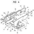
- Fig. 4 is an enlarged perspective view of the main portions of a merchandise handling truck employed in the first embodiment of the invention.
- the merchandise handling equipment 5 is a flat shelf type of merchandise handling equipment in which shelf plates 10 are arranged in multi-stage layers (in the illustrated embodiment, 6-stage layers) and a merchandise handling truck or carriage portion 6 is provided one in each of the multi-stage layers, the truck 6 being used to handle or move and put merchandise 7 onto each of the shelf plates 10.
- lifters 30 which are used to raise up and fall down the merchandise 7 to a given stage layer
- buffer conveyors 31 which are respectively used to put the merchandise 7 onto the lifter 30 and take out the merchandise 7 from the lifter 30 as well as provide temporary storage parts for storing thereon the merchandise 7 which is stored and shipped.
- a merchandise storing conveyor 32 which is used to load the merchandise 7 onto the lifter 30 and a merchandise shipping conveyor 33 used to take down the merchandise 7 from the lifter 30.
- the merchandise 7 having a small depth dimension is arranged in a plurality of lines (in the illustrated embodiment, in two lines) in the depth direction of the shelf plate 10.
- the merchandise handling truck 6 comprises a carriage 9 including a pallet 8 for placing the merchandise 7 thereon, a pair of left and right extendable and contractible fork members 13, 14 respectively provided in the two side end portions of the pallet 8, a fork width adjusting mechanism 11 for adjusting a mutually spaced distance between the pair of left and right fork members 13 and 14, a fork extending and contracting mechanism 12 for extending and contracting the pair of left and right fork members 13, 14 almost horizontally from the carriage 9 to the shelf plate 10 or vice versa, and front and rear end projecting members 16, 17 which are respectively provided on and projected from the front and rear ends of each of the left and right fork members 13, 14 in such a manner that they can be respectively situated in front of and in the rear of the merchandise 7 when the merchandise 7 is situated between the pair of left and right fork members 13 and 14.
- the pallet 8 as shown in Fig. 4, is made up of two flat plates 8a and 8b which are divided right and left, and the flat plates 8a and 8b are respectively formed integral with base forks 13a and 14a which are the composing elements of the fork members 13 and 14 corresponding to the flat plates 8a and 8b.
- the carriage 9 is arranged so as to run on a rail 19 provided along the front end portion of each of the shelf plates 10, that is, the carriage 9 is arranged such that it can be moved to an arbitrary position in the shelf plate 10.
- the left and right members 13 and 14 are structured such that they can be extended and contracted.
- the fork extending and contracting mechanism 12 extends and contracts the fork members 13 and 14 to thereby advance and retreat the top forks 23 on the shelf plate 10 side.
- the fork extending and contracting mechanism 12 comprises a drive motor 20 provided on the carriage 9, a spline shaft 35 which can be driven or rotated by the drive motor 20, pinion gears 24 which are supported rotatably on the base forks 13a and 14a and also which are meshable with drive gears 36 on the spline shaft 35 and thus can be rotated in linking with the spline shaft 35, rack gears (not shown) respectively formed integral with the lower end portions of the second forks 22 and meshable with the pinion gears 24, and wire connecting mechanisms (not shown) which, when the second forks 22 are caused to advance and retreat with respect to the base forks 13a and 14a by the rotational movements of the pinion gears 24, links the second forks 22 and top forks 23 with each other such that the top forks 23 can advance and retreat on the second for
- the above-mentioned wire connecting mechanism (not shown) for connecting the top fork 23 with the advancing and retreating movements of the second fork 22 employs an extending and contracting structure of a two-stage type that is disclosed in Japanese Patent Publication No. 4-112129 of Heisei, in which, when the second fork 22 is extended from the pallet 8 to the maximum, the top fork 23 is extended from the second fork 22 to the maximum and, when the second fork 22 returns back to its initial position on the pallet 8, the top fork 23 is stored within the second fork 22.
- the top fork 23 can be advanced from the pallet 8 to the shelf plate 10 and retreated from the shelf plate 10 to the pallet 8 almost horizontally along the depth direction (Z) of the shelf plate 10.
- the fork width adjusting mechanism 11 comprises a ball screw shaft 37 and a drive motor 38 which is used to drive and rotate the ball screw shaft 37.
- the ball screw shaft 37 as shown in Fig. 4, includes a left hand screw 39 and a right hand screw 40 which are respectively formed in the left and right end portions thereof.
- the left hand and right hand screws 39 and 40 are respectively in threaded engagement with blocks respectively formed integral with the flat plates 8a and 8b, so that the mutual space between the base forks 13a and 14a respectively formed integral with the flat plates 8a and 8b can be adjusted in accordance with the directions of rotation of the ball screw shaft 37.
- the front and rear end projecting members 16 and 17, in the present first embodiment, are respectively formed by bending inwardly the front and rear end portions of the top forks 23.
- intermediate projecting members 15 in the intermediate portions of the left and right top forks 23, there are provided intermediate projecting members 15, respectively.
- Each of the intermediate projecting members 15 is provided on and projected from the top fork 23 so that it can subdivide the distance between the front and rear end projecting members 16 and 17 provided in each of the right and left top forks 23 and, as shown in Fig. 4, the intermediate projecting member 15 is supported on the top fork 23 in such a manner that it can be swung or rotated in the vertical direction (XY). In particular, normally, it is rotated due to its own weight so that the leading end portion thereof projects inwardly.
- each of the intermediate projecting members 15 includes a roller 15a in the leading end portion thereof.
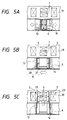
- the merchandise handling truck 6 When moving the merchandise 7 on the shelf plate 10 to the pallet 8 of the merchandise handling truck 6, at first, as shown in Fig. 5A, the merchandise handling truck 6 is moved to a position in front of the merchandise 7 to be moved onto the shelf plate 10.
- the fork width adjusting mechanism 11 is operated to adjust the distance between the left and right fork members 13 and 14 to be slightly greater than the width dimension of the merchandise 7 to be moved (in this case, the merchandise 7 of a small size arranged in two lines in the depth direction of the shelf plate 10).
- the intermediate projecting members 15 are inserted into a space S 1 between the pieces of the merchandise 7, 7 respectively arranged in the depth direction of the shelf plate 10 and functions as a separator to prevent the space S 1 from being disarranged while the pieces of the merchandise 7 are being handled or moved.
- front and rear end projecting members 16 and 17, which are respectively provided in the front and rear end portions of each of the top forks 23, respectively serve as stoppers to prevent the pieces of the merchandise 7, 7 held by and between the top forks 23, 23 from slipping off from between the top forks 23, 23 when the left and right fork members 13 and 14 are extended and contracted.
- the piece of the merchandise 7 may be pressed by the top forks 23 in such a manner that the piece of the merchandise 7 being held during the extension and contraction of the left and right fork members 13, 14 can slide on the shelf plate 10 without wobbling. That is, for this purpose, there is not necessary such a great holding force as can lift up the piece of the merchandise 7.
- the drive motor 38 which is the drive source of the fork width adjusting mechanism 11, can be reduced in size accordingly.
- the intermediate projecting members 15 When the merchandise 7 stored in a line on the shelf plate 10 is moved to the pallet 8 of the merchandise handling truck 6, the intermediate projecting members 15 are contacted with the side surfaces of the merchandise 7 when the merchandise 7 is held by and between the pair of top forks 23. However, in this case, the intermediate projecting members 15 contacted with the side surfaces of the merchandise 7, as shown in Figs. 7 and 8, are respectively rotated and retreated upwardly so that they do not interfere with the holding of the merchandise 7 by the top forks 23, 23.
- the moving or handling operation may be performed in the reverse procedure to the above-mentioned procedure provided when the merchandise 7 is moved from the shelf plate 10 to the merchandise handling truck 6.
- the movement of the merchandise 7 from one of the pallet 5 of the merchandise handling truck 6 and the shelf plate 10 to the other is carried out by allowing the left and right fork members 13 and 14 to hold the merchandise 7 between them and then by allowing the left and right fork members 13 and 14 to perform their own extension and contraction operations. Thanks to this, if the merchandise 7 to be moved is packed in a carton case or the like, then it is not necessary to move the merchandise 7 to a bucket or the like of a specific size but the merchandise 7 can be moved directly as it is, so that the efficiency of the merchandise handling operation can be improved.
- the size of the merchandise 7 to be moved is not limited to a specific size but the present merchandise handling equipment can also be used in handling or moving a wide variety of merchandise.
- the storage space on the shelf plate 10 it is sufficient to secure a space which corresponds to the actual width dimension of the merchandise plus a space permitting the insertion of the fork members 13 and 14 and, for the merchandise of a small size, the storage space on the shelf plate 10 can be reduced by an amount corresponding to the reduction in size of the merchandise. This eliminates the wasteful use of the storage space on the shelf plate 10 to thereby be able to enhance the storage efficiency of the shelf plate 10.
- the merchandise handling equipment according to the first embodiment of the invention is equipped with the merchandise handling trucks 6 one in each of the multi-stage layers of shelf plates 10. Due to this, the merchandise storing and shipping operations can be carried out at the same time in the respective multi-stage layers, which makes it possible to store and ship a large quantity of merchandise efficiently.
- FIGs. 9 and 10 respectively show a second embodiment of merchandise handling equipment according to the invention.
- Fig. 9 is a plan view of the whole structure of the second embodiment
- Fig. 10 is a side view of the whole structure of the second embodiment.
- the lifters 30 for lifting up and falling down the merchandise 7 to each of the multi-stage layers of shelf plates are provided not in the two end portions of the shelf plate 10 but in the intermediate portions of the shelf plate 10.
- the remaining portions of the merchandise handling equipment 42 according to the second embodiment are quite the same as those of the merchandise handling equipment 5 shown in Figs. 1 to 4.
- this lifter provision position provides the home position of the merchandise handling truck 6. This means that the running distance of the merchandise handling truck 6 from the lifter 30 to the end portion of the shelf plate 10 is about one half of the length of the shelf plate 10. Therefore, the running distance of the merchandise handling truck 6 necessary to handle or move the merchandise one time is shorter than the above embodiment shown in Fig. 3, so that the merchandise 7 storing and shipping performance of the present merchandise handling equipment can be enhanced.
- Figs. 11 to 13 respectively show a third embodiment of merchandise handling equipment according to the invention. That is, Fig. 11 is a plan view of the whole structure of the third embodiment, Fig. 12 is a side view of the whole structure of the third embodiment, and Fig. 13 is a perspective view of the whole structure of the third embodiment.
- the merchandise handling equipment 43 according to the third embodiment is equipped, by the side of the shelf plate 10, with a delivery line 44 for storing and shipping merchandise.
- the delivery line 44 includes a merchandise storing and shipping device, which consists of a merchandise storing buffer conveyor 45 and a merchandise shipping buffer conveyor 46, one in each of the shelf plates 10 of the respective multi-stage layers, a carry-in conveyor 48 for delivering the merchandise 7 to the merchandise storing buffer conveyor 45 through a merchandise storing tilt conveyor 47, and a carry-out conveyor 50 for carrying out the merchandise 7 stored in the merchandise shipping buffer conveyor 46 through a merchandise shipping tilt conveyor 49.
- the handling or movement of the merchandise 7 between the respective shelf plates 10 and the buffer conveyors 45, 46 is carried out by use of the merchandise handling truck 6.
- the structure of the merchandise handling truck 6 per se is the same as that employed in the first embodiment.
- this provision position provides the home position of the merchandise handling truck 6 for storing and shipping the merchandise.
- the running distance of the merchandise handling truck 6 is almost equal to the whole length of the shelf plate 10, that is, very long, when storing the merchandise 7 in the neighborhood of the shipping side end portion of the shelf plate 10, or when shipping the merchandise 7 stored in the neighborhood of the storing side end portion of the shelf plate 10.
- the mean running distance of the merchandise handling truck 6 is about one half of the whole running length, it is difficult to shorten the mean running distance and, therefore, it is impossible to enhance the merchandise storing and shipping performance of the merchandise handling equipment.
- the merchandise storing and shipping performance is determined by the performance of the lifter 30. However, to enhance the performance of the lifter 30, it is necessary to increase the moving speed or the placement area of the lifter 30, which leads to the complicated structure of the merchandise handling equipment and an increase in the cost thereof.
- the merchandise storing buffer conveyor 45 and the merchandise shipping buffer conveyor 46 are disposed in the central portion of the shelf plate 10 in the longitudinal direction thereof and thus the home position of the merchandise handling truck 6 lies at the central portion of the shelf plate 10, when the merchandise handling truck 6 moves to the neighborhoods of the two end portions of the shelf plate 10, the running distance of the merchandise handling truck 6 is short so that the merchandise handling performance of the truck 6 can be enhanced.
- the mean running distance of the merchandise handling truck 6 is about a quarter of the whole running length, so that the running time of the material handling truck 6 can be shortened and thus the performance of the merchandise handling truck 6 can be enhanced.
- the shelf plate 10 to be used can be selected by inclining the tilt conveyors 47, 49 without using a lifter, the present structure is simplified over a structure using a lifter and the merchandise storing and shipping performance thereof can be enhanced to a great extent.
- the merchandise 7 to be shipped more frequently is stored in central portion of the shelf plate or in the neighborhood of the central portion thereof, while the merchandise 7 to be shipped less frequently is stored in a portion remote from the central portion of the shelf plate. This can further enhance the merchandise storing and shipping performance of the merchandise handling equipment.
- the merchandise storing and shipping time can be shortened.
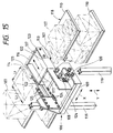
- FIG. 15 shows a fourth embodiment of a merchandise handling carriage portion or stacker crane according to the invention.
- a merchandise handling carriage portion or stacker crane 106 comprises a carriage 109 including a pallet 108 for placing merchandise 107 thereon, a pair of left and right fork members 113, 114 which are respectively provided in the two side end portions of the pallet 108 and are advanceable and retreatable substantially horizontally from the carriage 109 to the shelf plate 110, and front end and rear end push rods 116, 117 the two end portions of which are fixed to and supported by the pair of left and right fork members 113, 114 in such a manner that, when the left and right fork members 113, 114 are situated by the side of the merchandise 107 on the pallet 108 or on the shelf plate 110, the push rods 116, 117 are situated on the front end side of the merchandise 107 or on the rear end side thereof.
- the carriage 109 is supported by two masts 119 in such a manner that the carriage 109 can be moved at a proper time and by an arbitrary distance in the height direction of a shelf 118 (namely, in a direction of an arrow (Y) in Fig. 15) of a flat shelf structure including the shelf plates 110 in a plurality of stages (that is, the carriage 109 can be lifted and lowered).
- the masts 119 are arranged such that they are runnable or movable at a proper time and by an arbitrary distance in the extending direction of the shelf plate 110 (that is, in a direction of an arrow (X) in Fig. 15) by means of running means (not shown).
- the pair of left and right fork members 113, 114 employ an expansion and contraction structure which is disclosed in Japanese Patent Publication No. 4-112129 of Heisei. That is, the pair of left and right form members 113, 14 each includes a drive motor (namely, a fork back-and-forth drive motor) disposed on the carriage 109, a plurality of pinion gears 124 which are respectively disposed on the pallet 108 and can be rotationally driven by the drive motor 120, a plurality of guide rollers 125 which are respectively supported on the pallet 108 in a freely rotatable manner, a second fork 122 which can be advanced and retreated on the pallet 108 toward the shelf 118 side by means of the pinion gears 124 and guide rollers 125, and a top fork 123 advanceable and retreatable on the second fork 122 in linking with the advancing and retreating operations of the second fork 122.
- a drive motor namely, a fork back-and-forth drive motor
- the present structure is a two-stage expansion and contraction structure.
- the second forks 122 of the pair of left and right fork members 113, 114 are supported on the pallet 108 in such a manner that they are spaced from each other by a distance which is larger than the right and left direction length dimension L1 of the merchandise 107 to be moved. And, the front end and rear end push rods 116, 117 are spaced from each other by a distance larger than the back-and-forth direction length dimension L2 of the merchandise 107 to be moved, while the two end portions of the front end and rear end push rods 116, 117 are fixed to the top forks 123 of the pair of left and right fork members 113, 114, respectively.
- the pair of left and right top forks 123 and the front end and rear end push rods 116, 117 are arranged so as to form a frame which encloses the periphery of the merchandise 107 to be moved.
- the carriage 109 is raised and lowered so that the height positions of the pair of left and right fork members 113, 114 are situated in a space 130 formed above the merchandise 107 to be moved, and the pair of left and right fork members 113, 114 are extended to thereby allow the top forks 123 to project into the space 130 above the merchandise 107 to be moved.
- the carriage 109 is lowered a proper amount so that the merchandise 107 to be moved can be stored within the frame formed by the pair of left and right top forks 123 and the front end and rear end push rods 116, 117.
- the pair of left and right fork members 113, 114 are contracted so that the merchandise 107 to be moved can be slided on the shelf plate 110 and can be pushed onto the pallet 108 by the front end push rod 116.
- the carriage 109 is raised in such a manner that the pair of left and right fork members 113, 114 can be moved into the space 130 above the merchandise 107 to be moved, and, in this state, the pair of left and right fork members 113, 114 are contracted, thereby being able to complete the movement of the merchandise 107 onto the shelf plate 110.
- the movement of the merchandise 107 from one of the pallet 108 and shelf plate 110 to the other is carried out by advancing and retreating (that is, extending and contracting) the pair of left and right fork members 113, 114 and by allowing the merchandise 107 to slide on the pallet 108 or on the shelf plate 110 by means of the push rods 116, 117 which are pressed against the front end and rear end of the merchandise 107. Thanks to this, when compared with the structure disclosed in Japanese Patent Publication No. 7-25415 of Heisei in which the merchandise is held by use of the sucking disc, the movement of the merchandise can be carried out without any trouble even when the merchandise is stored in a case with holes.
- the push rods 116, 117 for pushing out the merchandise 107 are fixed to and supported by the top forks 123 of the fork members 113, 114, when compared with the structure disclosed in Japanese Patent Publication No. 6-345214 of Heisei in which the arms for pushing out the merchandise are arranged such that they are rotatable, there is eliminated the need to provide a mechanism and a drive source respectively used to drive the push rods on the fork members 113, 114. Due to this, the fork members 113, 114 to be inserted into the clearances between the merchandise can be designed to be fine and compact so that the fork members 113, 114 require a small space, and the clearances between the merchandise 107, 107 on the shelf plate 110 can be minimized. That is, in the structure according to the present embodiment of the invention, it is possible to enhance the storage efficiency of the merchandise 107 on the shelf plate 110.
- the fork members 113, 114 are arranged in such a 2-stage expansion and contraction structure as disclosed in Japanese Patent Publication No. 4-112129 of Heisei, even when compared with the structure disclosed in Japanese Patent Publication No. 7-25415 of Heisei in which the sucking disc is operated or moved, an increase in the dimension of the equipment in the moving direction of the merchandise 107 can be reduced and the equipment can be thereby made compact.
- the compact structure of the equipment in turn makes it possible to narrow the clearance between the shelf lines.
- the structure of the present embodiment thanks to the reduced clearance between the merchandise 107 on the shelf plate 110 and the narrowed clearance between the shelf lines, it can be expected that the storage efficiency of the merchandise in a warehouse or the like can be improved to a great extent.
- the front end and rear end push rods 116, 117 and the top forks 123 of the pair of left and right fork members 113, 114 supporting these push rods cooperate together in forming a frame for enclosing the periphery of the merchandise 107 to be moved, the loads to be applied to the fork members 113, 114 when the merchandise 107 is pushed out can be dispersed to the pair of left and right fork members 113, 114, that is, the loads can be reduced down to a half. For this reason, the strength to be secured for a fork member can be decreased and thus the diameters of the fork members 113, 114 can be reduced further. This makes it possible to reduce further the clearance between the merchandise 107, 107 on the shelf plate 110.
- a pair of front and rear push rods 116, 117 there are provided a pair of front and rear push rods 116, 117.
- this is not limitative but, alternatively, only one of them can be employed.
- the front end and rear end push rods 116, 117 are respectively supported between the top forks 123 of the pair of left and right fork members 113, 114.
- the intermediate push rod 115 may be provided between the front end and rear end push rods 116 and 117.
- the number of the intermediate push rod 115 is not limited to one, but two or more intermediate push rods 115 may also be provided.
- a plurality of merchandise 107, 107 respectively stored on the shelf plate 110 in the depth direction thereof can be drawn onto the pallet 108 at the same time, thereby being able to enhance the merchandise moving efficiency. Also, when moving the merchandise on the pallet 108 onto the shelf plate 110, a plurality of merchandise 107 can be moved at the same time, thereby being also able to improve the merchandise moving efficiency. Further, since the two pieces of merchandise 107 are separated by the intermediate push rod 115 when they are moved, there are formed clearances between the plurality of merchandise 107 that have been moved to the shelf plate 110 in the depth direction of the shelf plate 110.
- the push rod 116 can be inserted easily between the plurality of merchandise 107 stored in the depth direction of the shelf plate 110, so that the merchandise 107 can be taken out easily even when it is taken out individually one by one.
- the fork member 113 may be provided only in one side portion of the pallet 108, and the front end and rear end push rods 116, 117 may be supported in a cantilever manner by the top fork 123 of the fork member 113.
- the intermediate push rod 115 due to provision of the intermediate push rod 115, there can be obtained a similar effect to the above-mentioned structure.
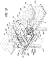
- Fig. 18 shows a fifth embodiment of a merchandise handling carriage portion or stacker crane according to the invention.
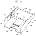
- the stacker crane 206 comprises a carriage 209 including a pallet 208 for placing merchandise 207 thereon, a pair of left and right fork members 213, 214 respectively provided in the two side end portions of the pallet 208, a fork width adjusting mechanism 211 for adjusting a mutually spaced distance between the pair of left and right fork members 213, 214, a fork advancing and retreating mechanism 212 for advancing and retreating the pair of left and right fork members 213, 214 almost horizontally from the carriage 209 to a shelf plate 210, and front end and rear end push rods 216, 217 which are respectively fixed and supported at the ends thereof to the pair of left and right fork members 213, 214 in such a manner that they are situated in front of or in the rear of the merchandise 207 when the merchandise 207 is situated between the pair of left and right fork members 213 and 214, and also which cooperate with the pair of left and right fork members 213, 214 in forming a frame for enclosing the pe
- the pallet 208 is made up of two flat plates 208a and 208b which are divided into the left and right plates, while the two flat plates 208a and 208b are respectively formed integral with base forks 213a and 213b which are respectively the composing elements of the fork members 213 and 214.
- the carriage 209 is supported by masts 219 in such a manner that they can be moved (that is, they can be raised up and fallen down) at a proper time and by an arbitrary distance in the height direction (in a direction of an arrow (Y) shown in Fig. 18) of a shelf 218 of a flat shelf type including a plurality of the shelf plates 210 which are arranged in a plurality of stages.
- the masts 219 are structured such that they are runnable at a proper time and by an arbitrary distance in the extending direction (in a direction of an arrow (X) shown in Fig. 18) of the shelf plate 210 by running means (not shown).
- the pair of left and right fork members 213, 214 respectively comprise the above-mentioned base forks 213a, 214a formed integral with the respective flat plates 208a, 208b of the pallet 208, second forks 222 respectively supported in such a manner that they can be advanced and retreated on the base forks 213a, 214a in the direction of the shelf 218 through guide rollers 225 respectively supported rotatably on the base forks 213a, 214a, and top forks 223 respectively advanceable and retreatable on the second forks 222 through guide rollers 221 in linking with the advancing and retreating operations of the second forks 222.
- the pair of left and right fork members 213, 214 are structured such that they can be expanded and contracted as a whole.
- the fork advancing and retreating mechanism 212 is used to advance and retreat the top forks 223 in the direction of the shelf 218 by expanding and contracting the fork members 213, 214.
- the fork advancing and retreating mechanism 212 comprises a drive motor 220 provided on the carriage 209, a spline shaft 232 which can be rotationally driven by the drive motor 220, pinion gears 224 which are respectively supported rotatably on the base forks 213a, 214a and also which are meshable with a drive gear 233 on the spline gear 232 and are thus rotatable in linking with the spline shaft 232, rack members 234 formed integral with the lower end portions of the second forks 222 and meshable with the pinion gears 224, and a wire connecting mechanism 235 (see Figs.
- the wire connecting mechanism 235 for connecting the top forks 223 with the advancing and retreating operations of the second forks 222 employs an expansion and contraction structure which is disclosed in Japanese Patent Publication No. 4-112129 of Heisei and, in addition, the wire connecting mechanism 235 is made compact in the height direction thereof.
- the wire connecting mechanism 235 provides a 2-stage expansion and contraction structure in which, when the second forks 222 are extended to the maximum from the pallet 208, the top forks 223 are extended to the maximum from the second forks 222 and, on the other hand, when the second forks 222 returns to their initial positions on the pallet 208, the top forks 223 are stored within the second forks 223 respectively.
- the top forks 223 are allowed to advance and retreat from the pallet 208 to the shelf plate 210 substantially horizontally in the depth direction (Z) of the shelf plate 210.
- the fork width adjusting mechanism 211 comprises a ball screw shaft 237 and a drive motor 238 for rotationally driving the ball screw shaft 237.
- the ball screw shaft 237 is a shaft which includes a left hand screw 239 and a right hand screw 240 respectively formed in the two ends thereof.
- the left hand and right hand screws 239, 240 are respectively in threaded engagement with blocks formed integral with the flat plates 208a, 208b and are used to adjust a mutually spaced distance between the base forks 213a, 214a formed integral with the flat plates 208a, 208b in accordance with the rotational direction of the ball screw shaft 237.
- the front end and rear end push rods 216, 217 are structured such that the respective base side ends thereof are fixed to the top forks 223 and the push rods 216, 217 respectively project inwardly of the frame from the left and right top forks 223.
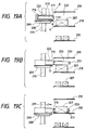
- the moving operation of the merchandise 207 is carried out in such a manner as shown in Figs. 19A to 19C and 20A to 20C.
- the carriage 209 is raised up and fallen down to adjust the height positions of the pair of left and right fork members 213, 214 so that the height positions of the front end and rear end push rods 216, 217 provided on the top forks 223 can be set in a space 230 existing above the merchandise 207 to be moved, and also the spaced distance between the pair of left and right fork members 213, 214 is adjusted by the fork width adjusting mechanism 211 to such an extent that the spaced distance between the pair of left and right fork members 213, 214 is slightly greater than the width dimension of the merchandise 207 to be moved.
- the pair of left and right fork members 213, 214 are extended by the fork advancing and retreating mechanism 212 to thereby allow the top forks 223 to project into the space 230 above the merchandise 207 to be moved.
- the carriage 209 is fallen down by a proper amount so that the merchandise 207 to be moved can be stored within the frame that is formed by the pair of left and right top forks 223 and the front end and rear end push rods 216, 217.
- the mutually opposing end edges of the pallet 208 and shelf plate 210 are respectively bent with an inclination K in order to prevent the end portions of the merchandise 207 to be moved from being caught by such end edges.
- the height position of the surface of the pallet 208 is set lower by a slight amount H1 than the height position of the surface of the shelf plate 210 in order that the merchandise 207 to be moved can made to slide to the pallet 208 side.
- the carriage 209 is raised and lowered in such a manner that the height position of the surface of the pallet 208 is set higher by a slight amount H2 than the height position of the surface of the shelf plate 210 and, next, as shown in Fig. 20C, the pair of left and right fork members 213, 214 are extended to thereby allow the front end push rod 216 to push out the merchandise 207 on the pallet 208 onto the shelf plate 210.
- the carriage 209 is raised in such a manner that the front end and rear end push rods 216, 217 on the pair of left and right fork members 213, 214 are moved to the space 230 existing above the merchandise 207 to be moved and, in this state, the pair of left and right fork members 213, 214 are contracted. This completes the operation to move the merchandise 207 onto the shelf plate 210.
- the movement of the merchandise 207 from one of the pallet 208 and shelf plate 210 to the other is carried out by advancing and retreating (extending and contracting) the pair of left and right fork members 213, 214 and by allowing the merchandise 207 to slide on the pallet 208 or on the shelf plate 210 by means of the push rods 216, 217 pressed against the front end or rear end of the merchandise 207. Due to this, when compared with the structure disclosed in Japanese Patent Publication No. 7-25415 of Heisei in which the merchandise is held by use of the sucking disc, the movement of the merchandise can be carried out without any trouble even when the merchandise is stored in a case with holes.
- the push rods 216, 217 for pushing out the merchandise 207 are structured such that they are fixed to and supported by the top forks 223 of the fork members 213, 14, when compared with the structure disclosed in Japanese Patent Publication No. 6-345214 of Heisei in which the arms for pushing out the merchandise are formed rotatable, there is eliminated the need to provide on the fork members 213, 214 a mechanism and a drive source respectively used to drive the push rods 216, 217. Due to this, the fork members 213, 214 to be inserted into the clearance between the merchandise 207 can be designed fine such that it requires a small space and also the clearance S (see Fig. 18) between the merchandise 207 on the shelf plate 210 can be reduced, so that the storage efficiency of the merchandise 207 on the shelf plate 210 can be enhanced.
- the loads to be applied to the fork members 213, 214 when the merchandise 207 is pushed out can be dispersed to the pair of left and right fork members 213 and thus the load to be applied to each of them can be reduced down to one half, that is, the strength to be secured for one form member can be lowered, so that the diameters of the fork members 213, 214 can be further reduced. This makes it possible to further reduce the clearance S between the merchandise 207 on the shelf plate 210.
- the two or more pieces of the merchandise 207 to be placed on the shelf plate 210 can be stored in such a manner that the clearance between them can be narrowed down to the clearance S which permits the insertion of the fork members 213, 214.
- the front end and rear end push rods 216, 217 provided in their respective left and right top forks 223 are both structured in a cantilever manner and the push rods opposed to each other in the width direction of the merchandise 207 to be moved are spaced apart from each other.
- a structure in which front end push rods 216a, 216b and rear front end push rods 217a, 217b respectively opposed to each other in the width direction of the merchandise 207 to be moved are formed as sliding pairs and are thus fitted with each other to be thereby connected with each other in the form of a single rod respectively. That is, there can be employed a frame structure in which the spaced distance between the fork members 213, 214 can be adjusted.
- Figs. 22 to 26B show a sixth embodiment of a stacker crane according to the invention.
- Fig. 22 is a perspective view of the whole structure of the sixth embodiment
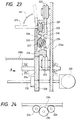
- Fig. 23 is a section view taken along the line 23-23 shown in Fig. 22
- Fig. 24 is an arrow view when viewed from a direction of an arrow B shown in Fig. 23
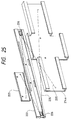
- Fig. 25 is a perspective view of a wire mechanism employed in the sixth embodiment, showing how the wires are extended
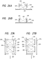
- Fig. 26A and 26B are explanatory views of the operation of the sixth embodiment shown in Fig. 22.
- intermediate push rods 215 are additionally provided one in each of the left and right top forks 223 which are the composing elements of the fork members 213, 214. Except for the additional provision of the intermediate push rods 215, the stacker crane 242 is similar in structure to the stacker crane 206 shown in Fig. 18.
- the upper and lower edges of the second fork 222 are formed as projecting portions each having a V-shaped section
- the base fork 214a includes in the upper and lower portions thereof guide rollers 225 each having a V-section groove engageable with the V-shaped projecting portion of the second fork 222, and the guide rollers 225 hold the second fork 222 between them from top and bottom in such a manner that the second fork 222 can run along the guide rollers 225.
- the top fork 223 also includes guide rollers 221 each having a V-section groove
- the second fork 222 includes a cutaway portion for a passage through which the guide rollers 221 of the top fork 223 run, the upper and lower edges of the inner surfaces of the cutaway portion are formed as projecting portions each having a V-shaped section, and the V-shaped projecting portions hold the guide rollers 221 of the top fork 223 between them from top and bottom in such a manner that the guide rollers 221 can run.
- a stopper 227 which prevents the top fork 223 from inclining or falling down.
- the second fork 222 At the two ends of the second fork 222 in the running direction thereof, there are respectively arranged pulleys having rotational surfaces which are inclined with respect to a vertical surface in mutually different directions, and wires 235 extended over the pulleys 226 are fixed to same side of the top fork 223 and base fork 214a, while, if the second fork 222 is extended and contracted, then the top fork 223 can also be extended and contracted.
- This structure is also employed in the first embodiment shown in Fig. 18. Since the second fork 222 is supported by the guide rollers 225 of the base fork 214a and the guide rollers 221 of the top fork 223 are supported within the cutaway portion of the second fork 222, the thickness of the second fork 222 can be reduced. Also, because the pulleys 226 over which the wires 235 are extended are arranged obliquely so that they can be stored within the thickness of the second fork 222, the thickness of the whole fork can be reduced.
- the intermediate push rods 215 are provided on and projected from the top forks 223 so that they subdivide the distance between the front end and rear end push rods 216, 217 respectively provided in the left and right top forks.
- the intermediate push rods 15 subdivide a frame, which is formed by the front end and rear end push rods 216, 217 and the pair of left and right top forks 223 so as to enclose the periphery of the merchandise 207, into two in the depth direction (Z) of the shelf plate 210.
- the intermediate push rods 215, as shown in Fig. 26A, are situated above the merchandise 207 by means of the expansion operation of the fork members 213, 214 by the fork width adjusting mechanism 211 and, after then, when the carriage 209 is lowered, as shown in Fig. 26B, the intermediate push rods 215 are supported by the top forks 223 swingably in the vertical direction (XY) so that they can retreat upwardly when they are contacted with the upper end of the merchandise 207.
- the reason why the above-mentioned intermediate push rods 215 are provided is that, when the merchandise 207 stored on the shelf plate 210 has a small dimension in the depth direction of the shelf plate 210 (that is, the dimension of the merchandise 207 in the back-and-forth direction thereof is small), the merchandise storage efficiency on the shelf plate 210 can be improved as well as the merchandise moving efficiency can be enhanced.
- the two pieces of the merchandise 207 placed on the shelf plate 210 in the depth direction thereof can be carried onto the pallet 208 at the same time, thereby being able to enhance the merchandise moving efficiency. And, also when the merchandise put on the pallet 208 is to be moved onto the shelf plate 210, the two pieces of the merchandise 207 can be moved together at the same time, which in turn can improve the merchandise moving efficiency. Still further, since the two pieces of the merchandise 207 are moved while they are separated by the intermediate push rods 215, there is formed a clearance between the two pieces of the merchandise 207 after they are moved onto the shelf plate 210 in the depth direction of the shelf plate 210.
- the rear end push rods 217 can be inserted between the two pieces of the merchandise 207 in the depth direction of the shelf plate 210 and thus the merchandise 207 can be taken out easily even one by one.
- the front end and rear end push rods 216, 217 and intermediate push rod 215 may be provided only in one of the right and left top forks 223.
- this structure as well, there can be obtained a similar effect to the above-mentioned structure.
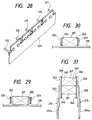
- the number of the intermediate push rod 215 provided between the front end and rear end push rods 216, 217 is not limited to one but, for example, as shown in Fig. 228, it is also possible that the number of the intermediate push rod 215 is increased to thereby increase further the number of pieces of the merchandise that can be moved together at the same time, so that the merchandise moving efficiency as well as the merchandise storage efficiency can be further enhanced.
- front end and rear end push rods 216, 217 may also be structured in such a manner that they can be swung in the vertical direction.
- Fig. 29 is a front view of the main portions of a seventh embodiment of a stacker crane according to the invention.
- two plate-shaped friction force increasing members 245 each formed of rubber or the like are provided on the respective inner surfaces of the top forks 223 of the fork members 213, 214 which are structured such that the mutually spaced distance between them in the width direction thereof can be adjusted.
- the merchandise 207 is handled or moved in such a manner that the merchandise 207 is held by and between the left and right top forks 223 and, in this state, the fork members 213, 214 are extended and contracted to thereby allow the merchandise 207 to slide on the pallet 208 or on the shelf plate 210.
- projections 246 are respectively provided in the front and rear ends of the friction force increasing members 245, then these projections 246 are allowed to have such functions as the front end and rear end push rods 216, 217, so that the reliability of the structure can be enhanced.
- the present structure eliminates the need to secure the space above the merchandise 207 for passage of the push rods, thereby being able to reduce the clearance between the shelf plates 210 by an amount corresponding to the eliminated space.
- an intermediate push rod 252 which can be swung in the vertical direction.
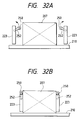
- the intermediate push rod 252 as shown in Fig. 32A, is energized at a waiting position by a spring or the like, while, at the waiting position, the intermediate push rod 252 projects at an angle not perpendicular to the top fork 223 and is held so as to face in the oblique direction in such a manner that the intermediate push rod 252 can be swung within a vertical surface.
- a roller 250 is provided at the leading end of each of the intermediate push rods 252.
- the rollers 250 are contacted with the merchandise 207 and, in response to this, as shown in Fig. 32B, the intermediate push rods 252 are caused to swing and retreat upwardly. Therefore, even when the merchandise 207 has such a large dimension in the back-and-forth direction thereof as intersects the intermediate push rods 252, since the intermediate push rods 252 are pressed and retreated by the merchandise 207 due to the horizontal movements of the top forks 223, there is no possibility that the intermediate push rods 252 can interfere with the movement of the merchandise 207 at all.
- the intermediate push rods 252 are respectively held at a waiting position where the intermediate push rods 252 faces in the downwardly oblique direction and they can be made to swing and retreat downwardly when they are contacted with and pushed by the merchandise 207.
- a merchandise handling truck 6 of the first embodiment is used as a merchandise handling equipment for a first, lowermost, shelf plate 10 1
- a stacker crane 206 of the fifth embodiment is used as a merchandise handling equipment common for second and third, two shelf plates 10 2 , 10 3
- a stacker crane 206 of the fifth embodiment is used as a merchandise handling equipment common for forth, fifth and sixth three shelf plates 10 4 , 10 5 and 10 6 .
- Fig. 33 a merchandise handling truck 6 of the first embodiment is used as a merchandise handling equipment for a first, lowermost, shelf plate 10 1
- a stacker crane 206 of the fifth embodiment is used as a merchandise handling equipment common for second and third, two shelf plates 10 2 , 10 3
- a stacker crane 206 of the fifth embodiment is used as a merchandise handling equipment common for forth, fifth and sixth three shelf plates 10 4 , 10 5 and 10 6 .
- reference numeral 30 designates a lifter; 31, a buffer conveyor; 33, a merchandise shipping conveyor.
- the merchandise handling truck 6 may be arranged such that the truck 6 can be moved beyond the lifter 31 to a position adjacent to the merchandise shipping conveyor 33 to transfer the merchandise directly from itself to the shipping conveyor 33.
Landscapes
- Engineering & Computer Science (AREA)
- Mechanical Engineering (AREA)
- Transportation (AREA)
- Structural Engineering (AREA)
- Civil Engineering (AREA)
- Life Sciences & Earth Sciences (AREA)
- Geology (AREA)
- Warehouses Or Storage Devices (AREA)
Applications Claiming Priority (6)
| Application Number | Priority Date | Filing Date | Title |
|---|---|---|---|
| JP6297595A JPH08258910A (ja) | 1995-03-22 | 1995-03-22 | スタッカークレーン |
| JP62975/95 | 1995-03-22 | ||
| JP7095375A JP2946281B2 (ja) | 1995-04-20 | 1995-04-20 | スタッカークレーン |
| JP95375/95 | 1995-04-20 | ||
| JP162178/95 | 1995-06-28 | ||
| JP16217895A JP2929426B2 (ja) | 1995-06-28 | 1995-06-28 | 物品保管設備 |
Publications (1)
| Publication Number | Publication Date |
|---|---|
| EP0733563A1 true EP0733563A1 (fr) | 1996-09-25 |
Family
ID=27298003
Family Applications (1)
| Application Number | Title | Priority Date | Filing Date |
|---|---|---|---|
| EP96104507A Withdrawn EP0733563A1 (fr) | 1995-03-22 | 1996-03-21 | Equipement de manutention et de stockage pour marchandises |
Country Status (1)
| Country | Link |
|---|---|
| EP (1) | EP0733563A1 (fr) |
Cited By (49)
| Publication number | Priority date | Publication date | Assignee | Title |
|---|---|---|---|---|
| EP0950623A1 (fr) * | 1998-04-17 | 1999-10-20 | MANNESMANN Aktiengesellschaft | Dispositif pour le stockage et le déstockage d'unités de chargement |
| DE10105706A1 (de) * | 2001-02-08 | 2002-09-05 | Siemens Production & Logistics | Regallager |
| EP1285866A1 (fr) * | 2001-08-23 | 2003-02-26 | KHT Kommissionier- und Handhabungstechnik GmbH | Magasin à rayonnage pour boItes rectangulaires en particulier des boItes à dimensions standardisées |
| EP1365975A4 (fr) * | 2001-01-26 | 2007-02-28 | Bakvertisi Ltd | Procede et appareil de stockage et de recuperation de contenants |
| WO2009079678A1 (fr) * | 2007-12-21 | 2009-07-02 | Tgw Mechanics Gmbh | Procédé d'emmagasinage d'auxiliaires de chargement, et dispositif de transport |
| WO2009086578A1 (fr) | 2008-01-11 | 2009-07-16 | Tgw Mechanics Gmbh | Procédé et dispositif de transport pour positionner des moyens de chargement avant leur transfert dans un compartiment de rayonnage |
| WO2009098573A1 (fr) * | 2008-02-04 | 2009-08-13 | S.I.T.I. Di Basso S.R.L. | Dispositif de chargement et de déchargement destiné à un appareil élévateur à translation |
| EP2165950A1 (fr) * | 2008-09-18 | 2010-03-24 | Rowa Automatisierungssysteme GmbH | Appareil de manoeuvre pour un magasin automatisé |
| EP2287093A1 (fr) * | 2009-08-19 | 2011-02-23 | psb intralogistics GmbH | Système de rayonnage et procédé de fonctionnement d'un système de rayonnage |
| EP2351698A1 (fr) | 2008-10-27 | 2011-08-03 | Dematic Accounting Services GmbH | Navette de transport pour entrepôt automatisé |
| EP2433882A1 (fr) * | 2010-09-22 | 2012-03-28 | TGW Mechanics GmbH | Procédé d'encastrement de produits et dispositif associé |
| WO2013006880A1 (fr) * | 2011-07-08 | 2013-01-17 | Tgw Mechanics Gmbh | Moyen de réception de charge destiné à déposer et enlever des marchandises |
| EP2551218A1 (fr) * | 2011-07-27 | 2013-01-30 | Dematic GmbH | Procédé de stockage et de préparation de commande |
| WO2013090958A1 (fr) | 2011-12-21 | 2013-06-27 | Tgw Logistics Group Gmbh | Système d'emmagasinage à rayonnages et son procédé de fonctionnement |
| US20140301811A1 (en) * | 2011-07-01 | 2014-10-09 | Effimat Storage Technology Aps | Vertical lift storage system and a method of operating a lift |
| WO2015027261A1 (fr) | 2013-08-27 | 2015-03-05 | Tgw Logistics Group Gmbh | Système d'entrepôt à rayonnages automatique |
| CN104619613A (zh) * | 2012-09-06 | 2015-05-13 | 村田机械株式会社 | 移载装置 |
| CN104619614A (zh) * | 2012-09-06 | 2015-05-13 | 村田机械株式会社 | 移载装置 |
| US20150217935A1 (en) * | 2012-09-05 | 2015-08-06 | Murata Machinery, Ltd. | Transfer device |
| US20150259141A1 (en) * | 2012-08-31 | 2015-09-17 | Murata Machinery, Ltd. | Transfer device |
| WO2015154116A3 (fr) * | 2014-04-08 | 2015-11-26 | Swisslog Evomatic Gmbh | Transtockeur |
| EP2526032B2 (fr) † | 2010-09-30 | 2016-07-06 | Dematic Systems GmbH | Navette pour entrepôt automatisé |
| WO2016168878A1 (fr) | 2015-04-22 | 2016-10-27 | Tgw Mechanics Gmbh | Procédé de mise en stock de charges isolées dans un rayonnage de stockage et système de stockage |
| CN104619613B (zh) * | 2012-09-06 | 2016-11-30 | 村田机械株式会社 | 移载装置 |
| EP3147237A1 (fr) | 2015-09-25 | 2017-03-29 | Vanderlande Industries B.V. | Système pour le stockage temporaire de produits tels que des bacs chargés ou non de bagages |
| EP3044127A4 (fr) * | 2013-09-13 | 2017-05-10 | Symbotic LLC | Système de stockage et de récupération automatisé |
| US9862543B2 (en) | 2010-12-15 | 2018-01-09 | Symbiotic, LLC | Bot payload alignment and sensing |
| FR3056565A1 (fr) * | 2016-09-27 | 2018-03-30 | Savoye | Dispositif de prehension de charges de tailles variables et procede d'adaptation de largeur de prehension correspondant |
| CN108620371A (zh) * | 2017-03-17 | 2018-10-09 | 亚智科技股份有限公司 | 基板清洗方法与清洗设备 |
| EP3166875A4 (fr) * | 2014-07-08 | 2019-03-06 | Dematic Corp. | Configuration de levage pour entrepôt à chariots |
| CN110182516A (zh) * | 2019-05-15 | 2019-08-30 | 盐城品迅智能科技服务有限公司 | 一种智能仓储装备用多自由度输送装置及平衡控制方法 |
| US10414587B2 (en) | 2016-07-19 | 2019-09-17 | Dematic Gmbh | Automatically centering load support for shuttle vehicles having a variable receiving width |
| EP2163507B2 (fr) † | 2008-09-15 | 2020-05-13 | Markus Erich Riedl | Poignée d'appareil de commande de rayonnage et procédé de fonctionnement de l'appareil de commande de rayonnage |
| US10894663B2 (en) | 2013-09-13 | 2021-01-19 | Symbotic Llc | Automated storage and retrieval system |
| CN112429446A (zh) * | 2019-08-26 | 2021-03-02 | 北京京东乾石科技有限公司 | 一种变距穿梭车货叉间距校正方法和装置 |
| KR20210034949A (ko) | 2019-09-23 | 2021-03-31 | 주식회사 티에스피지 | 주행대차용 텔레스코픽 포크장치 |
| EP3854727A1 (fr) * | 2020-01-24 | 2021-07-28 | Dematic Ltd. | Système de stockage |
| US11078017B2 (en) | 2010-12-15 | 2021-08-03 | Symbotic Llc | Automated bot with transfer arm |
| CN113401548A (zh) * | 2020-03-16 | 2021-09-17 | 因特利格雷特总部有限责任公司 | 用于多深度存放架的自动化穿梭车系统 |
| CN113683025A (zh) * | 2021-07-08 | 2021-11-23 | 长沙华恒机器人系统有限公司 | 一种变距夹抱式货叉装置 |
| CN114105051A (zh) * | 2021-11-15 | 2022-03-01 | 沈阳新松机器人自动化股份有限公司 | 一种自动调节货叉间距的移载机器人 |
| CN114313740A (zh) * | 2022-02-28 | 2022-04-12 | 普罗格智芯科技(湖北)有限公司 | 一种箱式两向车的取料装置 |
| EP4310026A1 (fr) | 2022-07-22 | 2024-01-24 | Goya Systec S.R.L. | Véhicule de transport pour entrepôts automatisés |
| WO2024094281A1 (fr) * | 2022-10-31 | 2024-05-10 | Dematic Gmbh | Système de stockage avec supports de stockage à niveaux multiples et procédé de fonctionnement pour fournir des unités de transport à partir d'une installation de stockage sur au moins une ligne de retrait |
| EP4400450A1 (fr) | 2023-01-12 | 2024-07-17 | Max Winkler | Rail de guidage ainsi qu'étagère dotée d'un rail de guidage |
| US20240300742A1 (en) * | 2020-12-24 | 2024-09-12 | Daifuku Co., Ltd. | Automated warehouse |
| US12103769B2 (en) | 2019-03-29 | 2024-10-01 | Daifuku Co., Ltd. | Transfer device |
| WO2024216322A2 (fr) | 2023-04-21 | 2024-10-24 | Tgw Mechanics Gmbh | Véhicule de transport utilisé à des fins de transport et procédé de manipulation de marchandises de détail dans un système de stockage |
| WO2025229254A1 (fr) * | 2024-04-30 | 2025-11-06 | Simec Systems Oy | Système de chargement pour charger une unité de transport |
Citations (5)
| Publication number | Priority date | Publication date | Assignee | Title |
|---|---|---|---|---|
| DE3324349C1 (de) * | 1983-07-06 | 1984-11-22 | Mannesmann AG, 4000 Düsseldorf | Regalanlage |
| JPS60102305A (ja) * | 1983-11-04 | 1985-06-06 | Toshiba Corp | 移動式入出庫装置 |
| FR2586657A1 (fr) * | 1985-09-04 | 1987-03-06 | Lapouyade Sa | Dispositif de prehension de supports ou de conteneurs de charges |
| JPH06345214A (ja) * | 1993-06-03 | 1994-12-20 | Daifuku Co Ltd | 移載装置 |
| EP0643010A1 (fr) * | 1993-09-15 | 1995-03-15 | MANNESMANN Aktiengesellschaft | Installation de transport pour déplacer des unités de chargement, particulièrement pour des chariots élévateurs d'un transtockeur |
-
1996
- 1996-03-21 EP EP96104507A patent/EP0733563A1/fr not_active Withdrawn
Patent Citations (5)
| Publication number | Priority date | Publication date | Assignee | Title |
|---|---|---|---|---|
| DE3324349C1 (de) * | 1983-07-06 | 1984-11-22 | Mannesmann AG, 4000 Düsseldorf | Regalanlage |
| JPS60102305A (ja) * | 1983-11-04 | 1985-06-06 | Toshiba Corp | 移動式入出庫装置 |
| FR2586657A1 (fr) * | 1985-09-04 | 1987-03-06 | Lapouyade Sa | Dispositif de prehension de supports ou de conteneurs de charges |
| JPH06345214A (ja) * | 1993-06-03 | 1994-12-20 | Daifuku Co Ltd | 移載装置 |
| EP0643010A1 (fr) * | 1993-09-15 | 1995-03-15 | MANNESMANN Aktiengesellschaft | Installation de transport pour déplacer des unités de chargement, particulièrement pour des chariots élévateurs d'un transtockeur |
Non-Patent Citations (2)
| Title |
|---|
| PATENT ABSTRACTS OF JAPAN vol. 9, no. 252 (M - 420)<1975> 9 October 1985 (1985-10-09) * |
| PATENT ABSTRACTS OF JAPAN vol. 940, no. 12 * |
Cited By (93)
| Publication number | Priority date | Publication date | Assignee | Title |
|---|---|---|---|---|
| EP0950623A1 (fr) * | 1998-04-17 | 1999-10-20 | MANNESMANN Aktiengesellschaft | Dispositif pour le stockage et le déstockage d'unités de chargement |
| US6234550B1 (en) | 1998-04-17 | 2001-05-22 | Mannesmann Ag | Pick-up apparatus for retrieving and depositing a load |
| EP1365975A4 (fr) * | 2001-01-26 | 2007-02-28 | Bakvertisi Ltd | Procede et appareil de stockage et de recuperation de contenants |
| DE10105706A1 (de) * | 2001-02-08 | 2002-09-05 | Siemens Production & Logistics | Regallager |
| EP1285866A1 (fr) * | 2001-08-23 | 2003-02-26 | KHT Kommissionier- und Handhabungstechnik GmbH | Magasin à rayonnage pour boItes rectangulaires en particulier des boItes à dimensions standardisées |
| WO2009079678A1 (fr) * | 2007-12-21 | 2009-07-02 | Tgw Mechanics Gmbh | Procédé d'emmagasinage d'auxiliaires de chargement, et dispositif de transport |
| US8740542B2 (en) | 2007-12-21 | 2014-06-03 | Tgw Mechanics Gmbh | Method for introducing loading auxiliary means of transport device |
| WO2009086578A1 (fr) | 2008-01-11 | 2009-07-16 | Tgw Mechanics Gmbh | Procédé et dispositif de transport pour positionner des moyens de chargement avant leur transfert dans un compartiment de rayonnage |
| US8596952B2 (en) | 2008-01-11 | 2013-12-03 | Tgw Mechanics Gmbh | Method and transport device for positioning loading aids prior to the transfer thereof into a shelf |
| WO2009098573A1 (fr) * | 2008-02-04 | 2009-08-13 | S.I.T.I. Di Basso S.R.L. | Dispositif de chargement et de déchargement destiné à un appareil élévateur à translation |
| EP2163507B2 (fr) † | 2008-09-15 | 2020-05-13 | Markus Erich Riedl | Poignée d'appareil de commande de rayonnage et procédé de fonctionnement de l'appareil de commande de rayonnage |
| EP2165950A1 (fr) * | 2008-09-18 | 2010-03-24 | Rowa Automatisierungssysteme GmbH | Appareil de manoeuvre pour un magasin automatisé |
| EP2351698A4 (fr) * | 2008-10-27 | 2013-01-16 | Dematic Accounting Serv Gmbh | Navette de transport pour entrepôt automatisé |
| EP2351698A1 (fr) | 2008-10-27 | 2011-08-03 | Dematic Accounting Services GmbH | Navette de transport pour entrepôt automatisé |
| US8790061B2 (en) | 2008-10-27 | 2014-07-29 | Dematic Accounting Services Gmbh | Transferring shuttle for three dimensional automated warehouse |
| EP2287093A1 (fr) * | 2009-08-19 | 2011-02-23 | psb intralogistics GmbH | Système de rayonnage et procédé de fonctionnement d'un système de rayonnage |
| EP2433882A1 (fr) * | 2010-09-22 | 2012-03-28 | TGW Mechanics GmbH | Procédé d'encastrement de produits et dispositif associé |
| EP2526032B2 (fr) † | 2010-09-30 | 2016-07-06 | Dematic Systems GmbH | Navette pour entrepôt automatisé |
| US9522781B2 (en) | 2010-09-30 | 2016-12-20 | Dematic Systems Gmbh | Shuttle for automated warehouse |
| US11078017B2 (en) | 2010-12-15 | 2021-08-03 | Symbotic Llc | Automated bot with transfer arm |
| US12214959B2 (en) | 2010-12-15 | 2025-02-04 | Symbotic Llc | Automated bot with transfer arm |
| US9862543B2 (en) | 2010-12-15 | 2018-01-09 | Symbiotic, LLC | Bot payload alignment and sensing |
| US20140301811A1 (en) * | 2011-07-01 | 2014-10-09 | Effimat Storage Technology Aps | Vertical lift storage system and a method of operating a lift |
| US9919870B2 (en) * | 2011-07-01 | 2018-03-20 | Effimat Storage Technology Aps | Vertical lift storage system and a method of operating a lift |
| WO2013006880A1 (fr) * | 2011-07-08 | 2013-01-17 | Tgw Mechanics Gmbh | Moyen de réception de charge destiné à déposer et enlever des marchandises |
| AT511641A3 (de) * | 2011-07-08 | 2013-07-15 | Tgw Mechanics Gmbh | Lastaufnahmemittel zum ein- und auslagern von ladegütern |
| US9254930B2 (en) | 2011-07-27 | 2016-02-09 | Dematic Gmbh | Method of storing and picking |
| AU2012207033B2 (en) * | 2011-07-27 | 2014-03-13 | Dematic Gmbh | Method of storing and picking |
| EP2551218A1 (fr) * | 2011-07-27 | 2013-01-30 | Dematic GmbH | Procédé de stockage et de préparation de commande |
| WO2013090970A2 (fr) | 2011-12-21 | 2013-06-27 | Tgw Logistics Group Gmbh | Système de stockage sur rayonnages et son procédé de fonctionnement |
| WO2013090958A1 (fr) | 2011-12-21 | 2013-06-27 | Tgw Logistics Group Gmbh | Système d'emmagasinage à rayonnages et son procédé de fonctionnement |
| EP2794432B1 (fr) | 2011-12-21 | 2019-03-06 | TGW Logistics Group GmbH | Système de stockage sur rayonnages et son procédé de fonctionnement |
| US10173839B2 (en) | 2011-12-21 | 2019-01-08 | Tgw Logistics Group Gmbh | Rack storage system and method for operating it |
| CN104169196A (zh) * | 2011-12-21 | 2014-11-26 | Tgw物流集团有限公司 | 货架仓储系统和用于运行货架仓储系统的方法 |
| WO2013090959A2 (fr) | 2011-12-21 | 2013-06-27 | Tgw Logistics Group Gmbh | Système de stockage sur rayonnages et son procédé de fonctionnement |
| CN104169196B (zh) * | 2011-12-21 | 2016-09-14 | Tgw物流集团有限公司 | 货架仓储系统和用于运行货架仓储系统的方法 |
| WO2013090970A3 (fr) * | 2011-12-21 | 2014-04-10 | Tgw Logistics Group Gmbh | Système de stockage sur rayonnages et son procédé de fonctionnement |
| EP2794431B1 (fr) | 2011-12-21 | 2017-05-03 | TGW Logistics Group GmbH | Système de stockage sur rayonnages et son procédé de fonctionnement |
| CN106276010A (zh) * | 2011-12-21 | 2017-01-04 | Tgw物流集团有限公司 | 货架仓储系统和用于运行货架仓储系统的方法 |
| US9701471B2 (en) * | 2012-08-31 | 2017-07-11 | Murata Machinery, Ltd. | Transfer device |
| US20150259141A1 (en) * | 2012-08-31 | 2015-09-17 | Murata Machinery, Ltd. | Transfer device |
| US9598236B2 (en) * | 2012-09-05 | 2017-03-21 | Murata Machinery, Ltd. | Transfer device |
| US20150217935A1 (en) * | 2012-09-05 | 2015-08-06 | Murata Machinery, Ltd. | Transfer device |
| CN104619613A (zh) * | 2012-09-06 | 2015-05-13 | 村田机械株式会社 | 移载装置 |
| CN104619613B (zh) * | 2012-09-06 | 2016-11-30 | 村田机械株式会社 | 移载装置 |
| CN104619614A (zh) * | 2012-09-06 | 2015-05-13 | 村田机械株式会社 | 移载装置 |
| CN104619614B (zh) * | 2012-09-06 | 2016-08-24 | 村田机械株式会社 | 移载装置 |
| US9764900B2 (en) | 2013-08-27 | 2017-09-19 | Tgw Logistics Group Gmbh | Automatic rack storage system |
| WO2015027261A1 (fr) | 2013-08-27 | 2015-03-05 | Tgw Logistics Group Gmbh | Système d'entrepôt à rayonnages automatique |
| US10894663B2 (en) | 2013-09-13 | 2021-01-19 | Symbotic Llc | Automated storage and retrieval system |
| US11708218B2 (en) | 2013-09-13 | 2023-07-25 | Symbolic Llc | Automated storage and retrieval system |
| EP3044127A4 (fr) * | 2013-09-13 | 2017-05-10 | Symbotic LLC | Système de stockage et de récupération automatisé |
| WO2015154116A3 (fr) * | 2014-04-08 | 2015-11-26 | Swisslog Evomatic Gmbh | Transtockeur |
| US10589928B2 (en) | 2014-04-08 | 2020-03-17 | Swisslog Evomatic Gmbh | Storage and retrieval machine |
| AU2015288140B2 (en) * | 2014-07-08 | 2019-11-07 | Dematic Corp. | Lift configuration for carriage-based warehouse |
| EP3166875A4 (fr) * | 2014-07-08 | 2019-03-06 | Dematic Corp. | Configuration de levage pour entrepôt à chariots |
| EP3286111B1 (fr) | 2015-04-22 | 2018-11-07 | TGW Mechanics GmbH | Procédé de mise en stock de charges isolées dans un rayonnage de stockage et système de stockage |
| DE202016009160U1 (de) | 2015-04-22 | 2023-03-28 | Tgw Mechanics Gmbh | Lagersystem |
| DE202016009161U1 (de) | 2015-04-22 | 2023-03-28 | Tgw Mechanics Gmbh | Lagersystem |
| WO2016168878A1 (fr) | 2015-04-22 | 2016-10-27 | Tgw Mechanics Gmbh | Procédé de mise en stock de charges isolées dans un rayonnage de stockage et système de stockage |
| WO2016168874A1 (fr) | 2015-04-22 | 2016-10-27 | Tgw Mechanics Gmbh | Procédé de mise en stock de charges isolées dans un rayonnage de stockage et système de stockage |
| US10710803B2 (en) | 2015-04-22 | 2020-07-14 | Tgw Mechanics Gmbh | Method for transferring part-load consignments to a storage rack for storage, and storage system |
| EP3147237A1 (fr) | 2015-09-25 | 2017-03-29 | Vanderlande Industries B.V. | Système pour le stockage temporaire de produits tels que des bacs chargés ou non de bagages |
| US10414587B2 (en) | 2016-07-19 | 2019-09-17 | Dematic Gmbh | Automatically centering load support for shuttle vehicles having a variable receiving width |
| CN109715526A (zh) * | 2016-09-27 | 2019-05-03 | 萨沃伊公司 | 夹持可变大小的负载的装置及调适夹持宽度的对应方法 |
| US10865042B2 (en) | 2016-09-27 | 2020-12-15 | Savoye | Device for gripping loads of variable sizes, and corresponding method for adapting gripping width |
| WO2018060031A1 (fr) * | 2016-09-27 | 2018-04-05 | Savoye | Dispositif de préhension de charges de tailles variables et procédé d'adaptation de largeur de préhension correspondant |
| FR3056565A1 (fr) * | 2016-09-27 | 2018-03-30 | Savoye | Dispositif de prehension de charges de tailles variables et procede d'adaptation de largeur de prehension correspondant |
| CN108620371A (zh) * | 2017-03-17 | 2018-10-09 | 亚智科技股份有限公司 | 基板清洗方法与清洗设备 |
| US12103769B2 (en) | 2019-03-29 | 2024-10-01 | Daifuku Co., Ltd. | Transfer device |
| CN110182516B (zh) * | 2019-05-15 | 2020-08-21 | 南通宏昇机械配件有限公司 | 一种智能仓储装备用多自由度输送装置及平衡控制方法 |
| CN110182516A (zh) * | 2019-05-15 | 2019-08-30 | 盐城品迅智能科技服务有限公司 | 一种智能仓储装备用多自由度输送装置及平衡控制方法 |
| CN112429446A (zh) * | 2019-08-26 | 2021-03-02 | 北京京东乾石科技有限公司 | 一种变距穿梭车货叉间距校正方法和装置 |
| CN112429446B (zh) * | 2019-08-26 | 2023-05-30 | 北京京东乾石科技有限公司 | 一种变距穿梭车货叉间距校正方法和装置 |
| KR20210034949A (ko) | 2019-09-23 | 2021-03-31 | 주식회사 티에스피지 | 주행대차용 텔레스코픽 포크장치 |
| EP3854727A1 (fr) * | 2020-01-24 | 2021-07-28 | Dematic Ltd. | Système de stockage |
| US11655101B2 (en) | 2020-01-24 | 2023-05-23 | Dematic Limited | Storage system |
| US12071304B2 (en) | 2020-03-16 | 2024-08-27 | Intelligrated Headquarters, Llc | Automated shuttle systems for multi-depth storage racks |
| EP3919414A1 (fr) * | 2020-03-16 | 2021-12-08 | Intelligrated Headquarters LLC | Systèmes de navette automatique pour râtelier de stockage à profondeurs multiples |
| CN113401548A (zh) * | 2020-03-16 | 2021-09-17 | 因特利格雷特总部有限责任公司 | 用于多深度存放架的自动化穿梭车系统 |
| CN116692337A (zh) * | 2020-03-16 | 2023-09-05 | 因特利格雷特总部有限责任公司 | 用于多深度存放架的自动化穿梭车系统 |
| US11820594B2 (en) | 2020-03-16 | 2023-11-21 | Intelligrated Headquarters, Llc | Automated shuttle systems for multi-depth storage racks |
| US12545519B2 (en) * | 2020-12-24 | 2026-02-10 | Daifuku Co., Ltd. | Automated warehouse |
| US20240300742A1 (en) * | 2020-12-24 | 2024-09-12 | Daifuku Co., Ltd. | Automated warehouse |
| CN113683025A (zh) * | 2021-07-08 | 2021-11-23 | 长沙华恒机器人系统有限公司 | 一种变距夹抱式货叉装置 |
| CN114105051A (zh) * | 2021-11-15 | 2022-03-01 | 沈阳新松机器人自动化股份有限公司 | 一种自动调节货叉间距的移载机器人 |
| CN114313740A (zh) * | 2022-02-28 | 2022-04-12 | 普罗格智芯科技(湖北)有限公司 | 一种箱式两向车的取料装置 |
| EP4310026A1 (fr) | 2022-07-22 | 2024-01-24 | Goya Systec S.R.L. | Véhicule de transport pour entrepôts automatisés |
| WO2024094281A1 (fr) * | 2022-10-31 | 2024-05-10 | Dematic Gmbh | Système de stockage avec supports de stockage à niveaux multiples et procédé de fonctionnement pour fournir des unités de transport à partir d'une installation de stockage sur au moins une ligne de retrait |
| DE102023100596A1 (de) | 2023-01-12 | 2024-07-18 | Max Winkler | Fahrschiene sowie Regal mit Fahrschiene |
| EP4400450A1 (fr) | 2023-01-12 | 2024-07-17 | Max Winkler | Rail de guidage ainsi qu'étagère dotée d'un rail de guidage |
| WO2024216322A2 (fr) | 2023-04-21 | 2024-10-24 | Tgw Mechanics Gmbh | Véhicule de transport utilisé à des fins de transport et procédé de manipulation de marchandises de détail dans un système de stockage |
| WO2025229254A1 (fr) * | 2024-04-30 | 2025-11-06 | Simec Systems Oy | Système de chargement pour charger une unité de transport |
Similar Documents
| Publication | Publication Date | Title |
|---|---|---|
| JP2946281B2 (ja) | スタッカークレーン | |
| CN117985630A (zh) | 一种便于码垛的电动伸缩臂式叉车 | |
| JP2929426B2 (ja) | 物品保管設備 | |
| CN116198882A (zh) | 码垛机器人 | |
| JP2008024493A (ja) | 物品移載装置 | |
| US4014442A (en) | Stacker crane for storehouses | |
| JP4678715B2 (ja) | 荷移載システム | |
| CN210213834U (zh) | 一种转件托盘 | |
| US8641356B2 (en) | Elevating conveyance device | |
| CN117326243A (zh) | 袋笼骨架自动立体化智能存放设备及全自动存取方法 | |
| CN216637684U (zh) | 货叉组件及仓储机器人 | |
| JP3136466B2 (ja) | スタッカークレーン式立体自動倉庫 | |
| JP2004123277A (ja) | 立体自動倉庫における荷の出入方法 | |
| JP2828413B2 (ja) | 詰出装置 | |
| JPS6036224A (ja) | デパレタイザ | |
| JP2726182B2 (ja) | 物品の保管・搬送用パレット | |
| JPS6153962B2 (fr) | ||
| EP1012076B1 (fr) | Systeme de stockage | |
| JPS6132205B2 (fr) | ||
| CN118651795A (zh) | 一种立体仓库用堆垛机 | |
| JP2669804B2 (ja) | 長尺物立体倉庫 | |
| JP2702661B2 (ja) | 成形製品集積装置 | |
| JPH01172108A (ja) | ピッキングヘッド搭載スタッカクレーンを備えた自動倉庫 | |
| JPH0825637B2 (ja) | 角管及び形鋼の段積み装置及び段積み方法 | |
| KR890003115Y1 (ko) | 자동창고의 스택커크레인의 포크구동장치 |
Legal Events
| Date | Code | Title | Description |
|---|---|---|---|
| PUAI | Public reference made under article 153(3) epc to a published international application that has entered the european phase |
Free format text: ORIGINAL CODE: 0009012 |
|
| AK | Designated contracting states |
Kind code of ref document: A1 Designated state(s): DE NL |
|
| STAA | Information on the status of an ep patent application or granted ep patent |
Free format text: STATUS: THE APPLICATION IS DEEMED TO BE WITHDRAWN |
|
| 18D | Application deemed to be withdrawn |
Effective date: 19970326 |