EP0733774B1 - Echelle métallique composée d'éléments métalliques facilement assemblables - Google Patents
Echelle métallique composée d'éléments métalliques facilement assemblables Download PDFInfo
- Publication number
- EP0733774B1 EP0733774B1 EP96830121A EP96830121A EP0733774B1 EP 0733774 B1 EP0733774 B1 EP 0733774B1 EP 96830121 A EP96830121 A EP 96830121A EP 96830121 A EP96830121 A EP 96830121A EP 0733774 B1 EP0733774 B1 EP 0733774B1
- Authority
- EP
- European Patent Office
- Prior art keywords
- ladder
- metal
- structural elements
- structural
- comprises moreover
- Prior art date
- Legal status (The legal status is an assumption and is not a legal conclusion. Google has not performed a legal analysis and makes no representation as to the accuracy of the status listed.)
- Expired - Lifetime
Links
- 229910052751 metal Inorganic materials 0.000 title claims abstract description 61
- 239000002184 metal Substances 0.000 title claims description 60
- 238000010276 construction Methods 0.000 claims abstract description 15
- 230000002787 reinforcement Effects 0.000 claims description 7
- 239000011248 coating agent Substances 0.000 claims description 4
- 238000000576 coating method Methods 0.000 claims description 4
- 239000004579 marble Substances 0.000 claims description 3
- 239000002023 wood Substances 0.000 claims description 2
- 230000008878 coupling Effects 0.000 claims 1
- 238000010168 coupling process Methods 0.000 claims 1
- 238000005859 coupling reaction Methods 0.000 claims 1
- 230000000452 restraining effect Effects 0.000 claims 1
- 230000004048 modification Effects 0.000 description 2
- 238000012986 modification Methods 0.000 description 2
- 230000000284 resting effect Effects 0.000 description 2
- 125000006850 spacer group Chemical group 0.000 description 2
- 239000007769 metal material Substances 0.000 description 1
- 238000000034 method Methods 0.000 description 1
- 230000003068 static effect Effects 0.000 description 1
Images





Classifications
-
- E—FIXED CONSTRUCTIONS
- E06—DOORS, WINDOWS, SHUTTERS, OR ROLLER BLINDS IN GENERAL; LADDERS
- E06C—LADDERS
- E06C7/00—Component parts, supporting parts, or accessories
- E06C7/08—Special construction of longitudinal members, or rungs or other treads
-
- E—FIXED CONSTRUCTIONS
- E04—BUILDING
- E04F—FINISHING WORK ON BUILDINGS, e.g. STAIRS, FLOORS
- E04F11/00—Stairways, ramps, or like structures; Balustrades; Handrails
- E04F11/02—Stairways; Layouts thereof
- E04F11/022—Stairways; Layouts thereof characterised by the supporting structure
- E04F11/035—Stairways consisting of a plurality of assembled modular parts without further support
-
- E—FIXED CONSTRUCTIONS
- E04—BUILDING
- E04F—FINISHING WORK ON BUILDINGS, e.g. STAIRS, FLOORS
- E04F11/00—Stairways, ramps, or like structures; Balustrades; Handrails
- E04F11/02—Stairways; Layouts thereof
- E04F11/104—Treads
- E04F11/112—Treads of metal or with an upper layer of metal
-
- E—FIXED CONSTRUCTIONS
- E06—DOORS, WINDOWS, SHUTTERS, OR ROLLER BLINDS IN GENERAL; LADDERS
- E06C—LADDERS
- E06C1/00—Ladders in general
- E06C1/02—Ladders in general with rigid longitudinal member or members
- E06C1/04—Ladders for resting against objects, e.g. walls poles, trees
- E06C1/08—Ladders for resting against objects, e.g. walls poles, trees multi-part
- E06C1/10—Sections fitted end to end
Definitions
- the present invention relates to an easily assembled metal ladder.
- the lattice constructions of the at present commercially available metal ladders are, in particular, constituted by several types of different elements which, moreover, are furthermore differentiated based on the type of ladder to be made.
- the aim of the present invention is to solve the above mentioned problem by providing a metal ladder, including a very reduced number of modular elements, which can be made at very low cost.
- a main object of the present invention is to provide such a metal ladder which can be simply and quickly assembled.
- Another object of the present invention is to provide such a metal ladder which, by a simple modification of the modular elements constituting the lader, can have either a rectilinear or curved profile, depending on the user requirements.
- Yet another object of the present invention is to provide such a metal ladder which is very safe and reliable in operation.
- each of the plurality of structural metal sheet elements has a substantially cross configuration, said cross configuration including four arms near the end portions of which are provided further holes for assembling, said structural elements being provided for mutual connection by screws, engaged in the assembling holes, in order to define lattice structures constituting the legs of the ladder.
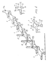
- the metal ladder according to the present invention comprises a bearing construction or structure, constituted by a plurality of structural elements 1, made of a sheet metal material, preferably cut by laser apparatus, or simply share-cut, the structural element being substantially equal to one another and being provided with a substantially cross configuration, including two vertical arms 2 and 3 and two horizontal arms 4 and 5.
- the cross arms 2, 3, 4, 5 are provided, near the free end portions thereof, with holes or perforations, 6, 7, 8, 9 which are used for assembling mutually the several structural elements 1, the assembling being performed by using assembling screws, for making grid or lattice constructions constituting the legs of the ladder, as is clearly shown in figure 1.
- the two horizontal arms 4 and 5 of the structural element 1 are offset in the height direction thereof, with respect to one another.
- the vertical arm 3 is connected to the horizontal arm 5 by a curved fitting or connection element.
- the horizontal arm 4 is likewise connected to the vertical arm 2 by a further curved fitting or connecting element.
- the vertical arms 2 and 3 are connected to one another and, along the axis thereof, middle holes or perforations 11 and 12 are formed, which are aligned or registered with the holes or perforations 6 and 7.
- the middle holes 11 and 12 are used, jointly with the holes 6 and 7, as well as with the holes 8 and 9, for fixing the ladder steps or for fixing, either on the inner face and/or on the outer face of the structural element 1, reinforcement plates, as it will be disclosed in a more detailed manner hereinafter.
- the several structural elements 1 are assembled mutually by using assembling screws, and by arranging a structural element 1 in an adjoining relationship with another structural element 1, so that the holes 6 of structural element 1 is aligned with the hole 8 of another structural element 1, whereas the hole 7 of a structural element 1 is aligned with the hole 9 of the other structural element 1 and so on, so as to obtain a ladder having a set or desired ladder height.
- the lattice or grid construction constituting a leg of the subject metal ladder will be practically constituted by a plurality of constructional elements 1, all equal to one another.
- an end element la which is substantially equal to the constructional or structural element 1, without the arm 4.
- the subject metal ladder is moreover provided with a ladder foot element 13 which can be associated, by means of an assembling screw, to the bottom vertical arm 2 of the structural element 1, constituting the bottom element of the lattice construction of the ladder.
- Inner reinforcement plates are moreover provided, indicated by the reference number 14, which are provided with a pair of holes 14a and 14b with an axis corresponding to the intra-axis of the holes 11 and 12 and which are applied on the inner side of the structural element 1, by assembling screws, engaged through the holes 11 and 12 aligned or registered with the holes 14a and 14b of the reinforcement plate 14.
- the ladder comprises moreover outer plates 15, also provided with holes 15a and 15b, the intra-axis of which corresponds to the intra-axis of the holes 11 and 12.
- the plates 15 can be associated with the outer face or surface of the structural elements 1, la, by possibly using those same screws which are used for assembling the inner plate 14.
- the plates 15 extend on the top of the structural elements 1, la with a portion thereof, therethrough are formed further holes or perforations 16, for connecting the upright support element of the ladder banisters.
- the banisters upright is engaged between the portion of the plates 15 extending on the top of the lattice construction, and inner plates 17 which are connected to the lattice construction, by using those same screws connecting two structural elements at the holes 9 and 7.
- the inner plates 17, in particular, are provided with additional holes or perforations 17a and 17b having an intra-axis equal to that of the holes 16.
- bracket elements 18, which can be connected on the inner side of the structural elements 1, by using those same assembling screws mutually connecting the structural elements, at the holes 7 and 9, together with other assembling screws engaged in the holes 12.
- the wood portion 19 of the step is connected to the assembling brackets 18 by means of assembling screws 20.
- a suitable bearing element would be provided, adapted to be connected to the legs of the ladder, by using those same holes 7 and 9 provided for mutually connecting the structural elements 1 and the middle holes 12.
- connection of the assembling brackets 18 and of the bearing elements of the lattice constructions, which constitute the two legs of the ladder, can be suitably performed by using threaded bushings 21 which are arranged between the assembling brackets 18 or the supporting or bearing element and the inner face of the structural elements 1, or of the possible reinforcement plate 14.
- the threaded bushings 21, in particular, are traversed by a threaded hole, therein is engaged, from a side, the assembling screw 22 connecting the structural elements 1 or the structural element to the reinforcement plate 14 and, on the other side, the screws 23 for connecting the brackets or the step bearing or supporting element.
- Both the assembling brackets 18 and the bearing element for supporting the marble steps are also preferably made of a sheet metal.
- a spacer disc element At the hole 12, between the step and inner face of the structural element 1, or of the inner reinforcement plate 14, is arranged a spacer disc element, in order to fit the different overall thickness of the ladder leg at said hole, with respect to the connection region of the holes 7 and 9.
- the intra-axis of the end holes 6 and 7 of the arms 2 and 3 can be changed, depending on the rise required for the steps of the subject metal ladder.
- the structural elements 1 and 1a can be curved or bent along the extension thereof, in order to provide either curved ladders or helical configuration ladders.
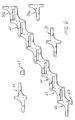
- Figure 6 illustrates a variation of the ladder according to the present invention, made of structural elements similar to the above disclosed structural elements.
- the bottom structural element 44 is also provided with a slightly different configuration from that of the other structural elements.
- the bars or rods 45 which are provided with end bushings 49, can be connected at the assembling holes 8 and 11 of the structural elements 1, thereby providing a different arrangement of the ladder step, with respect to the leg of the ladder.
- the metal ladder according to the present invention owing to the fact that the bearing construction is practically made of a single type of modular element, can be made at a very low cost, both from the making proper standpoint and from the assembling standpoint, which costs are anyhow much smaller than that of conventional types of metal prior ladder.
- an inner structural element 60 which has a bar or rod configuration, being provided with a central body 61 including spaced holes, according to that same principle which has been above disclosed for the rectilinear ladder, and being provided with a front lug 62 and a rear lug 63, with respect to the ladder extension, which are suitably slanted so as to provide the ladder with the desired slanted attitude.
- a bottom hole 64 On the body 61 are provided a bottom hole 64, a top hole 65, as well as a middle hole 66 which is arranged substantially flush with the rear lug 63.
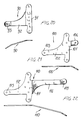
- An inner end structural element 75 is moreover provided, shown in figure 17, which has a central body 76 and a single front lug 77, also slanted with respect to the central body 76.
- an outer helical structural element 80 On the outer side, that is on the outer periphery of the helical ladder, is provided an outer helical structural element 80, which is conceptually analogous to the structural element 1 and which is substantially provided with a central body 81 therefrom extend front 82 and rear 83 arms, which are slanted with respect to the central body 81 and end with front 84 and rear 85 lugs, so as to provide the mutual inclination for obtaining the desired curvature ray.
- a starting outer structural element 86 shown in figure 18, which includes its central body 87 to which is connected a rear arm 88 ending with a rear lug 89.
- the outer end structural element would be of course moreover provided, for forming a helical ladder, said element being indicated by the reference number 90 in figure 20 and being provided with a central body 91 coupled to a front arm 92 ending with a front lug 93, all of these elements being mutually slanted.
- the elements which are herein used also allow to connect to one another ladders of rectilinear configuration including helical portions.
- an inner fitting or connecting structural element is moreover provided, shown in figure 21 and indicated by the reference number 100, which is substantially provided with a central body 101 to which is connected, on the same plane, a front arm 102 and a front lug 103, the rear lug 104 being provided with a slanted attitude.
- an outer fitting or connecting structural element 110 shown in figure 22, having a central body 111 coplanar with the front arm 112 and front lug 113 and slanted with respect to the rear arm 114 in turn slanted with respect to the rear lug 115.
- This step rise can be directly made as a single body with the sheet metal 140 constituting the structural element supporting the ladder step and which, on the front thereof, is provided with a slanted rise 141 to be coated by a coating 142 constituting the ladder step proper and allowing to make both the step rise and the step tread.
Landscapes
- Engineering & Computer Science (AREA)
- Architecture (AREA)
- Civil Engineering (AREA)
- Structural Engineering (AREA)
- Mechanical Engineering (AREA)
- Ladders (AREA)
- Steps, Ramps, And Handrails (AREA)
- Joining Of Building Structures In Genera (AREA)
Claims (27)
- Échelle métallique facilement assemblée comprenant une pluralité d'éléments porteurs modulaires formés d'éléments de structure de plaques métalliques, sensiblement égaux les uns aux autres, des orifices étant formés à travers lesdits éléments de structure pour fixer les échelons de l'échelle, caractérisée en ce que chacun desdits éléments de structure présente une configuration sensiblement en forme de croix, ladite configuration en forme de croix comprenant quatre bras à proximité des portions d'extrémité desquelles sont prévus d'autres orifices dpour l'assemblage, lesdits éléments de structure étant prévus pour une connexion mutuelle au moyen de vis, engagées dans les orifices d'assemblage, dans le but de définir des structures en treillis constitutives des montants de l'échelle.
- Échelle métallique, selon la revendication 1, caractérisée en ce que les deux bras horizontaux desdits éléments de structure sont décalés l'un de l'autre dans la direction de la hauteur.
- Échelle métallique, selon les revendications précédentes, caractérisée en ce que les deux bras verticaux desdits éléments de structure sont alignés mutuellement et en ce que des orifices intermédiaires sont formés le long de leur axe commun entre les orifices d'assemblage respectifs.
- Échelle métallique, selon l'une ou plus des revendications précédentes, caractérisée en ce que lesdits bras verticaux desdits éléments de structure sont reliés aux bras horizontaux par un élément de raccord courbé.
- Échelle métallique, selon l'une ou plus des revendications précédentes, caractérisée en ce que ladite échelle métallique comprend par ailleurs un élément pied qui peut être associé avec le bras vertical inférieur de l'élément de structure, constituant l'élément inférieur desdites constructions en treillis.
- Échelle métallique, selon l'une ou plus des revendications précédentes, caractérisée en ce que ladite échelle comprend de plus des éléments de structure d'extrémité qui sont sensiblement réalisés comme les autres éléments de structure, sans l'un des bras horizontaux.
- Échelle métallique, selon l'une ou plus des revendications précédentes, caractérisée en ce que ladite échelle comprend de plus des plaques de renfort destinées à être associées avec la face intérieure et/ou extérieure desdits éléments de structure.
- Échelle métallique, selon l'une ou plus des revendications précédentes, caractérisée en ce que ladite échelle comprend de plus des plaques de support pour supporter les bras de l'échelle, et qui peuvent être associées avec la face intérieure et/ou extérieure desdits éléments de structure.
- Échelle métallique, selon l'une ou plus des revendications précédentes, caractérisée en ce que ladite échelle comprend des éléments de support pour supporter les échelons de l'échelle, qui peuvent être associés avec lesdits éléments de structure par les mêmes vis d'assemblage des éléments de structure et au moyen d'autres vis destinés à être engagées dans les orifices intermédiaires.
- Échelle métallique, selon l'une ou plus des revendications précédentes, caractérisée en ce que lesdits éléments de structure sont équipés de portions coudées pour réaliser des échelles courbées ou en hélice.
- Échelle métallique, selon l'une ou plus des revendications précédentes, caractérisée en ce que ladite échelle comprend des brides de fixation de support d'échelon pour supporter des échelons de l'échelle en bois, et qui peuvent être appliquées sur la face intérieure des éléments de structure.
- Échelle métallique, selon l'une ou plus des revendications précédentes, caractérisée en ce que ladite échelle comprend de plus des éléments porteurs en feuille métallique pour supporter des échelons en marbre.
- Échelle métallique, selon l'une ou plus des revendications précédentes, caractérisée en ce que ladite échelle comprend de plus des douilles filetées pour attacher desdites brides de fixation ou les éléments porteurs ou supports auxdits éléments de structure.
- Échelle métallique, selon l'une ou plus des revendications précédentes, caractérisée en ce que ladite échelle comprend de plus une barre tubulaire, munie d'un orifice traversant pour un engagement dans celui-ci de vis de maintien pour tenir un élément de type plaque formant ledit échelon d'échelle.
- Échelle métallique, selon l'une ou plus des revendications précédentes, caractérisée en ce que ladite échelle comprend de plus un élément pied porteur, constitué par deux portions espacées et disposées en fourche, qui peuvent être reliées à la portion d'extrémité de l'élément de structure et s'étendant à partir d'un élément de base.
- Échelle métallique, selon l'une ou plus des revendications précédentes, caractérisée en ce que ladite échelle comprend de plus, pour la réalisation d'échelles en hélice, des éléments de structure présentant des portions mutuellement inclinées.
- Échelle métallique, selon l'une ou plus des revendications précédentes, caractérisée en ce que ladite échelle comprend de plus un élément de structure intérieur pour une échelle en hélice, présentant une portion centrale à laquelle sont reliées une oreille avant et une oreille arrière qui sont mutuellement inclinées par rapport à la portion centrale.
- Échelle métallique, selon l'une ou plus des revendications précédentes, caractérisée en ce que ladite échelle comprend de plus un élément de structure intérieur de départ pour une échelle en hélice, ayant un corps central à partir duquel s'étend une oreille arrière inclinée.
- Échelle métallique, selon l'une ou plus des revendications précédentes, caractérisée en ce que ladite échelle comprend de plus un élément de structure intérieur d'extrémité présentant un corps central à partir duquel s'étend une oreille avant inclinée.
- Échelle métallique, selon l'une ou plus des revendications précédentes, caractérisée en ce que ladite échelle comprend de plus un élément de structure extérieur pour une échelle en hélice, qui est muni d'un corps central auquel sont reliés un bras avant et un bras arrière se terminant respectivement par une oreille avant et une oreille arrière qui sont mutuellement inclinées.
- Échelle métallique, selon l'une ou plus des revendications précédentes, caractérisée en ce que ladite échelle comprend de plus un élément de structure extérieur de départ présentant un corps central à partir duquel s'étend un bras arrière, qui se termine par une oreille arrièreinclinée.
- Échelle métallique, selon l'une ou plus des revendications précédentes, caractérisée en ce que ladite échelle comprend de plus un élément de structure extérieur d'extrémité présentant un corps central à partir duquel s'étend un bras avant se terminant par une oreille avant inclinée.
- Échelle métallique, selon l'une ou plus des revendications précédentes, caractérisée en ce que ladite échelle comprend de plus un élément de structure intérieur de raccord présentant un corps central disposé en relation coplanaire avec un bras avant se terminant par une oreille avant, une oreille arrière inclinée étant de plus prévue.
- Échelle métallique, selon l'une ou plus des revendications précédentes, caractérisée en ce que ladite échelle comprend de plus un élément de structure extérieur de raccord présentant un corps central à partir duquel s'étend un bras avant coplanaire avec la portion centrale et une oreille avant, un bras arrière incliné se terminant par une oreille arrière inclinée étant de plus prévu.
- Échelle métallique, selon l'une ou plus des revendications précédentes, caractérisée en ce que ledit élément de type plaque, constituant l'échelon de l'échelle, est équipé de portions crénelées pour un couplage avec une contremarche.
- Échelle métallique, selon l'une ou plus des revendications précédentes, caractérisée en ce que ladite échelle comprend de plus des éléments de type plaque constituant la base de support pour un revêtement formant ledit échelon d'échelle.
- Échelle métallique, selon l'une ou plus des revendications précédentes, caractérisée en ce que ladite échelle comprend de plus un élément de type plaque en feuille métallique formant une plaque en un seul bloc, sur la marche de l'échelon, et une autre plaque, sur la contremarche de l'échelon.
Applications Claiming Priority (2)
| Application Number | Priority Date | Filing Date | Title |
|---|---|---|---|
| ITMI950564 | 1995-03-21 | ||
| IT95MI000564A IT1279005B1 (it) | 1995-03-21 | 1995-03-21 | Scala metallica con struttura portante ad elementi modulari ad elevata semplicita' di assemblaggio |
Publications (2)
| Publication Number | Publication Date |
|---|---|
| EP0733774A1 EP0733774A1 (fr) | 1996-09-25 |
| EP0733774B1 true EP0733774B1 (fr) | 1999-11-03 |
Family
ID=11371007
Family Applications (1)
| Application Number | Title | Priority Date | Filing Date |
|---|---|---|---|
| EP96830121A Expired - Lifetime EP0733774B1 (fr) | 1995-03-21 | 1996-03-18 | Echelle métallique composée d'éléments métalliques facilement assemblables |
Country Status (7)
| Country | Link |
|---|---|
| EP (1) | EP0733774B1 (fr) |
| AT (1) | ATE186371T1 (fr) |
| DE (1) | DE69604954T2 (fr) |
| ES (1) | ES2140815T3 (fr) |
| GR (1) | GR3032578T3 (fr) |
| IT (1) | IT1279005B1 (fr) |
| PT (1) | PT733774E (fr) |
Families Citing this family (6)
| Publication number | Priority date | Publication date | Assignee | Title |
|---|---|---|---|---|
| ITVI980052A1 (it) * | 1998-03-12 | 1999-09-12 | Massimo Mastella | Unita' di gradino modulare per scale prefabbricate autoportanti, non che' scala prefabbricata autoportante incorporante tale unita'. |
| ITVR20010037A1 (it) * | 2001-03-20 | 2002-09-20 | Renato Mastella | Struttura di trave lamellare |
| ITMI20071884A1 (it) * | 2007-10-02 | 2009-04-03 | Alessandro Maltini | Elemento modulare per la realizzazione di scale fisse |
| ITVR20080070A1 (it) * | 2008-06-20 | 2009-12-21 | Mast S R L | Struttura di scala e giunto strutturale per la realizzazione di scale |
| CN104775750B (zh) * | 2015-04-06 | 2016-08-24 | 陈超 | 一种剪叉式梯子 |
| WO2017042641A1 (fr) * | 2015-09-07 | 2017-03-16 | Crima S.R.L. | Marche pour escalier modulaire |
Family Cites Families (10)
| Publication number | Priority date | Publication date | Assignee | Title |
|---|---|---|---|---|
| GB151487A (en) * | 1919-10-14 | 1920-09-30 | William Andrew Sydne Hall | Step ladder |
| FR604662A (fr) * | 1925-09-16 | 1926-05-11 | Escaliers métalliques | |
| FR893503A (fr) * | 1941-05-26 | 1944-07-30 | échelle-escalier repliable | |
| BE740190A (fr) * | 1969-10-13 | 1970-03-16 | ||
| CH554998A (de) * | 1972-10-31 | 1974-10-15 | Arcia Sa | Echelle pliante. |
| BE872495A (fr) * | 1978-12-04 | 1979-03-30 | Willemsens Albert H | Escalier tournant |
| CA1145526A (fr) * | 1981-01-21 | 1983-05-03 | Leopold Lapointe | Volee d'escalier modulaire et auto-portante et montants pour la fabrication de celle-ci |
| US4355700A (en) * | 1981-02-17 | 1982-10-26 | Matthews Wesley D | Modular stairway system for installation on structures having non-linear walls |
| DE3505688A1 (de) * | 1985-02-19 | 1986-08-21 | Otto 5223 Nümbrecht Raschke | Tragekonstruktion fuer eine freitragende treppe |
| FR2597909B1 (fr) * | 1986-04-25 | 1991-05-17 | Abello Jean Baptiste | Escalier demontable en bois et a faux limon |
-
1995
- 1995-03-21 IT IT95MI000564A patent/IT1279005B1/it active IP Right Grant
-
1996
- 1996-03-18 EP EP96830121A patent/EP0733774B1/fr not_active Expired - Lifetime
- 1996-03-18 PT PT96830121T patent/PT733774E/pt unknown
- 1996-03-18 AT AT96830121T patent/ATE186371T1/de not_active IP Right Cessation
- 1996-03-18 DE DE69604954T patent/DE69604954T2/de not_active Expired - Fee Related
- 1996-03-18 ES ES96830121T patent/ES2140815T3/es not_active Expired - Lifetime
-
2000
- 2000-02-03 GR GR20000400273T patent/GR3032578T3/el not_active IP Right Cessation
Also Published As
| Publication number | Publication date |
|---|---|
| ITMI950564A1 (it) | 1996-09-21 |
| DE69604954D1 (de) | 1999-12-09 |
| EP0733774A1 (fr) | 1996-09-25 |
| IT1279005B1 (it) | 1997-12-02 |
| PT733774E (pt) | 2000-04-28 |
| DE69604954T2 (de) | 2000-06-29 |
| ATE186371T1 (de) | 1999-11-15 |
| ITMI950564A0 (it) | 1995-03-21 |
| ES2140815T3 (es) | 2000-03-01 |
| GR3032578T3 (en) | 2000-05-31 |
Similar Documents
| Publication | Publication Date | Title |
|---|---|---|
| KR900006626A (ko) | 가변 관성을 갖는 공간격자로 된 금속 구조물 및 그 건축방법 | |
| EP0733774B1 (fr) | Echelle métallique composée d'éléments métalliques facilement assemblables | |
| EP0263916B1 (fr) | Support modulaire pour marches d'escalier | |
| JPH0343424B2 (fr) | ||
| GB2226060A (en) | Support foot for raised floors | |
| JPH0444655B2 (fr) | ||
| KR970015980A (ko) | 건축용 슬라브 폼(Form) 지지장치 | |
| JP4586047B2 (ja) | 階段 | |
| JP2004076281A (ja) | 螺旋階段 | |
| JP4075519B2 (ja) | 階段 | |
| CN120625925A (zh) | 一种基于装配式设计的钢结构建筑加固方法 | |
| JPH0454272Y2 (fr) | ||
| JPH0643335Y2 (ja) | 手摺りの笠木支柱取付装置 | |
| JP4100185B2 (ja) | 階段の支承体 | |
| JPH0113757Y2 (fr) | ||
| JPS6128832Y2 (fr) | ||
| JPS638287Y2 (fr) | ||
| JP4586045B2 (ja) | 螺旋階段 | |
| JP3026115B2 (ja) | 建物の施工方法 | |
| JP4075518B2 (ja) | 階段 | |
| JP4134825B2 (ja) | 階段 | |
| JP4586048B2 (ja) | 階段 | |
| JPH05263461A (ja) | 片持ち型バルコニー及びその床フレーム | |
| JPH0510101Y2 (fr) | ||
| JP2000213134A (ja) | 螺旋階段の組立構造 |
Legal Events
| Date | Code | Title | Description |
|---|---|---|---|
| PUAI | Public reference made under article 153(3) epc to a published international application that has entered the european phase |
Free format text: ORIGINAL CODE: 0009012 |
|
| AK | Designated contracting states |
Kind code of ref document: A1 Designated state(s): AT BE CH DE ES FR GB GR IT LI LU MC NL PT |
|
| 17P | Request for examination filed |
Effective date: 19961217 |
|
| GRAG | Despatch of communication of intention to grant |
Free format text: ORIGINAL CODE: EPIDOS AGRA |
|
| 17Q | First examination report despatched |
Effective date: 19990210 |
|
| GRAG | Despatch of communication of intention to grant |
Free format text: ORIGINAL CODE: EPIDOS AGRA |
|
| GRAH | Despatch of communication of intention to grant a patent |
Free format text: ORIGINAL CODE: EPIDOS IGRA |
|
| GRAH | Despatch of communication of intention to grant a patent |
Free format text: ORIGINAL CODE: EPIDOS IGRA |
|
| GRAA | (expected) grant |
Free format text: ORIGINAL CODE: 0009210 |
|
| AK | Designated contracting states |
Kind code of ref document: B1 Designated state(s): AT BE CH DE ES FR GB GR IT LI LU MC NL PT |
|
| REF | Corresponds to: |
Ref document number: 186371 Country of ref document: AT Date of ref document: 19991115 Kind code of ref document: T |
|
| REG | Reference to a national code |
Ref country code: CH Ref legal event code: EP |
|
| REF | Corresponds to: |
Ref document number: 69604954 Country of ref document: DE Date of ref document: 19991209 |
|
| ITF | It: translation for a ep patent filed | ||
| REG | Reference to a national code |
Ref country code: CH Ref legal event code: NV Representative=s name: CABINET ROLAND NITHARDT CONSEILS EN PROPRIETE INDU |
|
| REG | Reference to a national code |
Ref country code: ES Ref legal event code: FG2A Ref document number: 2140815 Country of ref document: ES Kind code of ref document: T3 |
|
| ET | Fr: translation filed | ||
| REG | Reference to a national code |
Ref country code: PT Ref legal event code: SC4A Free format text: AVAILABILITY OF NATIONAL TRANSLATION Effective date: 20000124 |
|
| PLBE | No opposition filed within time limit |
Free format text: ORIGINAL CODE: 0009261 |
|
| STAA | Information on the status of an ep patent application or granted ep patent |
Free format text: STATUS: NO OPPOSITION FILED WITHIN TIME LIMIT |
|
| 26N | No opposition filed | ||
| REG | Reference to a national code |
Ref country code: GB Ref legal event code: IF02 |
|
| REG | Reference to a national code |
Ref country code: CH Ref legal event code: NV Representative=s name: BOVARD AG PATENTANWAELTE |
|
| PGFP | Annual fee paid to national office [announced via postgrant information from national office to epo] |
Ref country code: FR Payment date: 20060302 Year of fee payment: 11 |
|
| PGFP | Annual fee paid to national office [announced via postgrant information from national office to epo] |
Ref country code: MC Payment date: 20060303 Year of fee payment: 11 Ref country code: BE Payment date: 20060303 Year of fee payment: 11 |
|
| PGFP | Annual fee paid to national office [announced via postgrant information from national office to epo] |
Ref country code: PT Payment date: 20060306 Year of fee payment: 11 |
|
| PGFP | Annual fee paid to national office [announced via postgrant information from national office to epo] |
Ref country code: CH Payment date: 20060308 Year of fee payment: 11 |
|
| PGFP | Annual fee paid to national office [announced via postgrant information from national office to epo] |
Ref country code: ES Payment date: 20060310 Year of fee payment: 11 Ref country code: DE Payment date: 20060310 Year of fee payment: 11 |
|
| PGFP | Annual fee paid to national office [announced via postgrant information from national office to epo] |
Ref country code: AT Payment date: 20060314 Year of fee payment: 11 |
|
| PGFP | Annual fee paid to national office [announced via postgrant information from national office to epo] |
Ref country code: GB Payment date: 20060315 Year of fee payment: 11 |
|
| PGFP | Annual fee paid to national office [announced via postgrant information from national office to epo] |
Ref country code: LU Payment date: 20060323 Year of fee payment: 11 |
|
| PGFP | Annual fee paid to national office [announced via postgrant information from national office to epo] |
Ref country code: NL Payment date: 20060331 Year of fee payment: 11 Ref country code: GR Payment date: 20060331 Year of fee payment: 11 |
|
| PG25 | Lapsed in a contracting state [announced via postgrant information from national office to epo] |
Ref country code: PT Free format text: LAPSE BECAUSE OF NON-PAYMENT OF DUE FEES Effective date: 20070918 |
|
| REG | Reference to a national code |
Ref country code: PT Ref legal event code: MM4A Free format text: LAPSE DUE TO NON-PAYMENT OF FEES Effective date: 20070918 |
|
| REG | Reference to a national code |
Ref country code: CH Ref legal event code: PL |
|
| PG25 | Lapsed in a contracting state [announced via postgrant information from national office to epo] |
Ref country code: AT Free format text: LAPSE BECAUSE OF NON-PAYMENT OF DUE FEES Effective date: 20070318 |
|
| GBPC | Gb: european patent ceased through non-payment of renewal fee |
Effective date: 20070318 |
|
| NLV4 | Nl: lapsed or anulled due to non-payment of the annual fee |
Effective date: 20071001 |
|
| BERE | Be: lapsed |
Owner name: *CAVALER GIOVANNI Effective date: 20070331 Owner name: *MASTELLA RENATO Effective date: 20070331 |
|
| PG25 | Lapsed in a contracting state [announced via postgrant information from national office to epo] |
Ref country code: BE Free format text: LAPSE BECAUSE OF NON-PAYMENT OF DUE FEES Effective date: 20070331 |
|
| REG | Reference to a national code |
Ref country code: FR Ref legal event code: ST Effective date: 20071130 |
|
| PG25 | Lapsed in a contracting state [announced via postgrant information from national office to epo] |
Ref country code: NL Free format text: LAPSE BECAUSE OF NON-PAYMENT OF DUE FEES Effective date: 20071001 Ref country code: MC Free format text: LAPSE BECAUSE OF NON-PAYMENT OF DUE FEES Effective date: 20070331 Ref country code: DE Free format text: LAPSE BECAUSE OF NON-PAYMENT OF DUE FEES Effective date: 20071002 |
|
| PG25 | Lapsed in a contracting state [announced via postgrant information from national office to epo] |
Ref country code: LI Free format text: LAPSE BECAUSE OF NON-PAYMENT OF DUE FEES Effective date: 20070331 Ref country code: CH Free format text: LAPSE BECAUSE OF NON-PAYMENT OF DUE FEES Effective date: 20070331 |
|
| PG25 | Lapsed in a contracting state [announced via postgrant information from national office to epo] |
Ref country code: GB Free format text: LAPSE BECAUSE OF NON-PAYMENT OF DUE FEES Effective date: 20070318 |
|
| REG | Reference to a national code |
Ref country code: ES Ref legal event code: FD2A Effective date: 20070319 |
|
| PG25 | Lapsed in a contracting state [announced via postgrant information from national office to epo] |
Ref country code: FR Free format text: LAPSE BECAUSE OF NON-PAYMENT OF DUE FEES Effective date: 20070402 Ref country code: ES Free format text: LAPSE BECAUSE OF NON-PAYMENT OF DUE FEES Effective date: 20070319 |
|
| PG25 | Lapsed in a contracting state [announced via postgrant information from national office to epo] |
Ref country code: GR Free format text: LAPSE BECAUSE OF NON-PAYMENT OF DUE FEES Effective date: 20071003 |
|
| PG25 | Lapsed in a contracting state [announced via postgrant information from national office to epo] |
Ref country code: LU Free format text: LAPSE BECAUSE OF NON-PAYMENT OF DUE FEES Effective date: 20070318 |
|
| PGFP | Annual fee paid to national office [announced via postgrant information from national office to epo] |
Ref country code: IT Payment date: 20130329 Year of fee payment: 18 |
|
| PG25 | Lapsed in a contracting state [announced via postgrant information from national office to epo] |
Ref country code: IT Free format text: LAPSE BECAUSE OF NON-PAYMENT OF DUE FEES Effective date: 20140318 |