EP0733778A2 - Schneideinsatz für Fräsbohrmeissel - Google Patents
Schneideinsatz für Fräsbohrmeissel Download PDFInfo
- Publication number
- EP0733778A2 EP0733778A2 EP96301963A EP96301963A EP0733778A2 EP 0733778 A2 EP0733778 A2 EP 0733778A2 EP 96301963 A EP96301963 A EP 96301963A EP 96301963 A EP96301963 A EP 96301963A EP 0733778 A2 EP0733778 A2 EP 0733778A2
- Authority
- EP
- European Patent Office
- Prior art keywords
- substrate
- cutting table
- cutting
- cutter according
- peripheral edge
- Prior art date
- Legal status (The legal status is an assumption and is not a legal conclusion. Google has not performed a legal analysis and makes no representation as to the accuracy of the status listed.)
- Granted
Links
Images

Classifications
-
- E—FIXED CONSTRUCTIONS
- E21—EARTH OR ROCK DRILLING; MINING
- E21B—EARTH OR ROCK DRILLING; OBTAINING OIL, GAS, WATER, SOLUBLE OR MELTABLE MATERIALS OR A SLURRY OF MINERALS FROM WELLS
- E21B10/00—Drill bits
- E21B10/46—Drill bits characterised by wear resisting parts, e.g. diamond inserts
- E21B10/56—Button-type inserts
- E21B10/567—Button-type inserts with preformed cutting elements mounted on a distinct support, e.g. polycrystalline inserts
- E21B10/573—Button-type inserts with preformed cutting elements mounted on a distinct support, e.g. polycrystalline inserts characterised by support details, e.g. the substrate construction or the interface between the substrate and the cutting element
Definitions
- the invention relates to cutters for drag-type rotary drill bits for use in drilling or coring holes in subsurface formations.
- Such rotary drill bits comprise a bit body having a shank for connection to a drill string, a plurality of cutters mounted at the surface of the bit body, and a passage in the bit body for supplying drilling fluid to the surface of the bit for cleaning and/or cooling the cutters.
- Each cutter comprises a preform cutting element mounted in a socket on the bit body or on a carrier which is then mounted in a socket on the bit body.
- preform cutting element comprises a tablet, for example circular, having a thin cutting table of superhard material, such as polycrystalline diamond, bonded to a thicker substrate of less hard material, such as tungsten carbide.
- the thickness of the substrate may be such that the substrate itself forms a stud which may be directly mounted in a socket in the bit body.
- the cutting element may be mounted on a carrier, for example by the brazing process known as "LS bonding". The carrier is then mounted in a socket in the bit body.
- bit body itself may be machined from metal, usually steel, or moulded using a powder metallurgy process.
- cutters of this type may be susceptible to impact damage, due for example to heavy impact of the drill bit on the borehole bottom while being introduced into the borehole, or as a result of impact on harder occlusions in the formation being drilled.
- impact damage is likely to be increased as a result of the stress concentration which can occur at the sharp cutting edge between the front cutting face of the superhard layer and the peripheral edge of the cutting layer and substrate.
- Impact damage is particularly likely to occur when the cutters are new and before a wear flat has been formed on the superhard cutting table and substrate at the cutting edge.
- British Patent Specification No. 2276645 discloses a further development of this concept in which the substrate is also bevelled so as to increase in lateral extent beyond the cutting edge as it extends rearwardly from the superhard cutting table.
- the cutting table and substrate are both circular in cross-section and coaxial.
- the portion of the substrate immediately adjacent the cutting table is frusto-conical in shape and tapers outwardly from the periphery of the cutting table to the cylindrical portion of the remainder of the substrate, which is of greater diameter than the cutting table.
- the frusto-conical portion of the substrate is coaxial with the cutting table and substrate so that the rearward extent of its outer surface is constant around the periphery of the cutting table.
- the substrate including the cylindrical carrier on which it is mounted if such carrier is provided, is received within an appropriately shaped part-cylindrical socket in the bit body, and is usually secured within the socket by brazing.
- the part-cylindrical socket normally embraces only a portion of the periphery of the substrate and carrier, leaving a significant portion exposed. It is currently considered that increasing the exposure of cutters above the bit body increases the rate of penetration of the drill bit, but increasing the exposure tends to decrease the area of the surface of the cutter which is brazed within the socket. In order for the cutter to be securely retained, therefore, it is important that as much of the available surface area as possible is strongly brazed within the socket.
- the socket in which the cutter is received is shown as apparently having a frusto-conical mouth portion which closely engages the tapered portion of the substrate or carrier.
- the socket will normally be cylindrical and of constant cross-section corresponding to the larger diameter portion ofthe carrier or substrate. Consequently, once the cutter is located in the socket there is a part annular gap left between the peripheral wall of the socket and the frusto-conical portion of the substrate. In practice, this gap will usually be filled with braze material.
- the region of the frusto-conical portion of the substrate which is opposite the cutting edge may not be adequately attached to, or supported by, the surrounding bit body with the result that the heavy stresses imparted to the cutter in use may result in fracture or detachment of the cutter from the bit body.
- the provision of a frusto-conical portion of substrate adjacent the cutting table may reduce the concentration of stress at the cutting edge, it may in fact tend to weaken the cutter, and its attachment to the bit body, in other respects.
- the present invention sets out to provide a novel form of cutter where this disadvantage may be overcome.
- a cutter for a rotary drill bit comprising a cutting table of superhard material bonded to a less hard substrate, the cutting table having a front face and a peripheral edge at least a part of which defines a convexly curved cutting region, and the substrate including at least a portion thereof which increases in lateral extent beyond at least said curved cutting region of the peripheral edge of the cutting table as it extends rearwardly therefrom, the rearward extent of the outer surface of said portion varying around the periphery of the cutting table.
- the substrate may include a further portion which does not increase in lateral extent beyond the peripheral edge of the cutting table as it extends rearwardly thereof.
- said outer surface of the laterally increased portion of the substrate has a rearward extent which is a maximum adjacent a part of said convexly curved cutting region of the cutting table, the rearward extent decreasing, preferably smoothly and substantially linearly, as the substrate extends away from said part of cutting region to a second region of the peripheral edge of the cutting table.
- the cutting element is so orientated on the drill bit that its convexly curved cutting region, where the surface of said laterally increased portion is a maximum, engages the earthen formation being drilled, and in a region where the substrate is attached to the drill bit the rearward extent of said laterally increased portion is a minimum, for example is zero.
- This allows the peripheral surface of the substrate to absorb impact loads in the vicinity of the cutting edge, while at the same time not unduly reducing the area of contact between the substrate and its socket in regions away from the cutting edge.
- Said region of minimum rearward extent is preferably diametrically opposite said part of the cutting region.
- the substrate may comprise a substantially unitary body of said less hard material to which the cutting table is bonded, or it may comprise a first portion to which the cutting table is bonded, said first portion being in turn bonded to a second, carrier portion.
- the substrate may be of generally circular cross-section and generally cylindrical in form, except for said portion of increasing lateral extent.
- the invention also includes within its scope arrangements where the cutting table and substrate are non-circular and/or non-cylindrical in shape.
- said portion of the substrate of increasing lateral extent may be generally frusto-conical in shape.
- the variation in rearward extent of the outer surface of the frusto-conical portion may be effected by the axis of the frusto-conical portion being offset from the central axis of the rest of the substrate.
- the axis of the frusto-conical portion may be parallel to, and spaced from, the axis of the rest of the substrate, or may be inclined with respect to said axis.
- the angle of the frusto-conical portion of the substrate, and the offset of its axis, are so selected that the rearward extent of the outer surface of said frusto-conical portion is substantially zero in one region of the peripheral edge of the cutting table.
- peripheral edge of the cutting table may be chamfered, and preferably the chamfered peripheral edge of the cutting table blends substantially smoothly with the adjacent surface of the laterally increased portion of the substrate.
- the invention includes within its cope a method of forming a cutter for a rotary drill bit, the method comprising forming an intermediate structure comprising a cutting table of superhard material, having a front face and a peripheral edge, bonded to a less hard substrate, and then removing material from the intermediate structure, adjacent the cutting table, to form on the cutting table a convexly curved cutting region, and to form on the substrate at least a portion thereof which increases in lateral extent beyond at least the curved cutting region of the peripheral edge of the cutting table as it extends rearwardly therefrom, the rearward extent of the outer surface of said portion varying around the periphery of the cutting table.
- Said material may, for example, be removed from the intermediate structure by rotating the intermediate structure relative to a material removing device about a second axis so as to form said convexly curved cutting region on said peripheral edge of the cutting table and to form on said substrate a frusto-conical surface adjacent said cutting region, said second axis being offset with respect to said longitudinal axis of the substrate so as to vary the extent to which the outer surface of said frusto-conical surface extends rearwardly of the peripheral edge of the cutting table.
- the prior art cutter 10 comprises a circular thin cutting table 11 of polycrystalline diamond bonded, in a high pressure, high temperature press to a substrate 12 of tungsten carbide.
- the substrate 12 is cylindrical and of circular cross-section and is coaxial with the cutting table 11.
- the substrate 12 may comprise a unitary body of tungsten carbide the whole of which is bonded to the polycrystalline diamond cutting table 11 in the press.
- the substrate may comprise a thinner portion of tungsten carbide which is bonded to the polycrystalline diamond cutting table 11 in the press to form a cutting element, the tungsten carbide layer of the cutting element then being bonded to a separately formed cylindrical carrier of tungsten carbide, for example by brazing.
- the term "substrate” will be used to refer to the body of material behind the polycrystalline diamond cutting table 11 in both types of construction.
- the portion 13 of the substrate 12 immediately to the rear of the cutting table 11 is frusto-conical in shape, the half-angle of the cone being for example, about 10°.
- the central axis of the frusto-conical portion 13 is coincident with the longitudinal axis 14 of the cutter so that the substrate has a constant 10° bevel around the whole of its periphery.
- the peripheral edge 15 of the cutting table 11 is similarly bevelled so as to blend smoothly with the frusto-conical portion 13.
- Impact loads can be imposed on the cutting edge 20 of the cutter in a number of directions, and the principal directions are indicated by arrows in Figure 1.
- impact loads can be aligned along the drag direction, parallel to the surface of the formation 18, as indicated by the arrow 6; in the weight-on-bit direction 7, generally at right angles to the surface of the formation; and, due to bit whirl and backwards rotation, typically in a direction indicated by the arrow 8 in Figure 1.
- Any total impact load is therefore likely to be aligned anywhere in the angle between the arrows 6 and 8 and generally, therefore, the impact load can be resolved into two components in the drag direction 6 and weight-on-bit direction 7 respectively.
- a substantial proportion of the substrate 12 is received within a cylindrical socket 16 in a blade 17 formed on the bit body, such blades usually extending outwardly away from the central axis of rotation of the bit.
- a blade 17 formed on the bit body, such blades usually extending outwardly away from the central axis of rotation of the bit.
- braze joint strength is typically at a maximum at a thickness of 10-40 ⁇ m.
- the majority of the triangular gap 19 surrounding the frusto-conical portion 13 of the substrate will be filled with braze material which is much thicker than the optimum and may for example be as great as 350 ⁇ m in thickness.
- the braze joint in the gap 19 will therefore be weak compared with the braze joint between the rest of the substrate 12 and the socket 16. Not only does this increase the risk of the cutter becoming detached from the socket under heavy stresses, but it also means that the substrate is less effectively supported by the bit body in the very region, i.e. opposite the cutting edge 20, where adequate support is most needed.
- braze material in this region is less rigid than the material forming the socket, especially in the case of matrix-bodied bits, it acts rather like a soft spring and impact loads acting on the cutting edge 20 generally in the weight-on-bit direction 7 or bit whirl direction 8 may therefore have a tendency to lever the cutter out of its socket.
- Another disadvantage of a thick braze joint being provided around the exposed cutting face of the cutter is that this increases the tendency for the exposed line of braze material to be eroded by the flow of drilling mud over the cutter, such erosion being particularly common in respect of cutters located in the vicinity of the nozzles which deliver drilling mud to the surface of the drill bit.
- the bevelled shape of the portion 13 of the substrate may reduce the impact loads on the cutting edge 20 itself, the effect of the bevel may also be to weaken the cutter and its attachment to the bit body in other respects.
- FIGS 2 and 3 show an arrangement according to the present invention whereby this disadvantage may be overcome.
- the basic structure of the cutter of Figures 2 and 3 is similar to that of the prior art cutter of Figure 1 in that it comprises a polycrystalline diamond cutting table 21 bonded to a substrate 22 of circular cross-section which is received in a cylindrical socket 23 in a blade 24 on the bit body.
- the substrate 22 is formed with a frusto-conical portion 25 immediately rearward of the cutting table 21.
- the outer surface of the portion 25 is not of constant rearward extent as in the prior art arrangement, but its rearward extent varies as it is extends around the periphery of the cutting table 21.
- the rearward extent of the outer surface of the portion 25 is a maximum adjacent the central part 26a of the convexly curved cutting edge 26 ofthe cutting table 21 but reduces linearly as it extends away from the central part of the cutting edge, becoming zero at the location 27 diametrically opposite the centre of the cutting edge 26.
- the substrate is fully bevelled, for example at an angle of 10°, adjacent the central part of the cutting edge 26 so as to provide the impact resilience which is believed to result from the provision of such bevel.
- the rearward extent of the bevelled surface reduces in the portions of the substrate which lie within the socket 23, a larger surface area of the cylindrical part of the substrate 22 is in close contact with the walls of the socket 23 resulting in a strong brazed joint.
- the whole ofthe bevel is reduced to zero so that the whole of the cylindrical portion of the substrate is closely adjacent and brazed to the wall of the socket 23, thus providing good support for the substrate in this region.
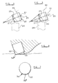
- Figures 4 and 5 show two alternative methods for achieving a construction of the kind shown in Figures 2 and 3.
- an intermediate structure is first formed comprising the cutting table 21 of circular cross-section bonded to the cylindrical substrate 22 of the same diameter as the cutting table 21.
- the intermediate structure is presented to a grinding wheel, indicated diagrammatically at 28, with the longitudinal axis 29 of the intermediate structure arranged at a required angle, for example 10°, to the peripheral surface of the grinding wheel 28.
- the intermediate structure is held in a chuck, indicated diagrammatically at 30, for rotation about an axis 31 which is parallel to and spaced from the longitudinal axis 29 of the intermediate structure.
- the intermediate structure is then rotated in contact with the grinding wheel 21 so as to form the bevelled portion 25.
- the offsetting of the axis of rotation 31 of the intermediate structure from the central longitudinal axis 29 of the structure has the result that the width of the outer surface of the frusto-conical portion 25 varies linearly around the periphery of the structure.
- the offset distance between the axes is so selected that the minimum rearward extent of the surface of the portion 25 from the cutting table 21 is zero.
- the invention includes within its scope arrangements where the rearward extent is not reduced to zero but where a smaller extent of bevel is formed opposite the maximum extent of bevel.
- the cutting table 21 is flat and planar and is coaxial with the substrate 22.
- the invention includes within its scope arrangements in which the cutting table is not flat but is profiled on its rear face and/or on its front face.
- the cutting table 21 might be dished or domed or may be formed on its rearward surface with projections with project into the material of the substrate 22.
- the substrate need not necessarily be cylindrical in shape or circular in cross-section.
- the bevelled portion 25 is preferably frusto-conical, since then it may be readily formed by rotating the intermediate structure in contact with a grinding wheel or other material-removing device, such as an EDM device, the invention includes within its scope arrangements where the surface is not frusto-conical and where the rearward extent of the bevelled surface does not vary linearly around the periphery of the cutter.
- the substrate of the cutter may be appropriately shaped by other known machining or cutting processes, or the cutter may be moulded in the required shape in the high pressure, high temperature press.
- the bevelled portion 25 of the cutter extends around substantially the whole periphery of the substrate, reducing to zero width only at the position 27 directly opposite the centre 26a of the cutting edge 26.
- the bevel 32 extends around only a portion of the substrate 33, leaving a significant portion of the periphery of the substrate furthest away from the centre 34a of the cutting edge 34 unbevelled and thus able to be brazed strongly within the cylindrical socket.
- the bevel may, for example, extend around about half the periphery of the substrate.
- the method described in relation to Figures 4 and 5 is a convenient method of forming a cutter according to the present invention, other forming processes may be employed.
- the cutter may be cut to the desired shape by wire electrical discharge machining or other cutting processes which may allow non-conical, non-symmetrical shapes to be achieved more easily.
Landscapes
- Engineering & Computer Science (AREA)
- Life Sciences & Earth Sciences (AREA)
- Mining & Mineral Resources (AREA)
- Geology (AREA)
- Mechanical Engineering (AREA)
- Physics & Mathematics (AREA)
- Environmental & Geological Engineering (AREA)
- Fluid Mechanics (AREA)
- Chemical & Material Sciences (AREA)
- Crystallography & Structural Chemistry (AREA)
- General Life Sciences & Earth Sciences (AREA)
- Geochemistry & Mineralogy (AREA)
- Drilling Tools (AREA)
- Earth Drilling (AREA)
Applications Claiming Priority (2)
| Application Number | Priority Date | Filing Date | Title |
|---|---|---|---|
| GB9505922 | 1995-03-23 | ||
| GBGB9505922.6A GB9505922D0 (en) | 1995-03-23 | 1995-03-23 | Improvements in or relating to cutters for rotary drill bits |
Publications (3)
| Publication Number | Publication Date |
|---|---|
| EP0733778A2 true EP0733778A2 (de) | 1996-09-25 |
| EP0733778A3 EP0733778A3 (de) | 1996-11-13 |
| EP0733778B1 EP0733778B1 (de) | 2000-10-25 |
Family
ID=10771752
Family Applications (1)
| Application Number | Title | Priority Date | Filing Date |
|---|---|---|---|
| EP96301963A Expired - Lifetime EP0733778B1 (de) | 1995-03-23 | 1996-03-21 | Schneideinsatz für Fräsbohrmeissel |
Country Status (4)
| Country | Link |
|---|---|
| US (1) | US5769175A (de) |
| EP (1) | EP0733778B1 (de) |
| DE (1) | DE69610729T2 (de) |
| GB (2) | GB9505922D0 (de) |
Families Citing this family (4)
| Publication number | Priority date | Publication date | Assignee | Title |
|---|---|---|---|---|
| US5967249A (en) * | 1997-02-03 | 1999-10-19 | Baker Hughes Incorporated | Superabrasive cutters with structure aligned to loading and method of drilling |
| US6345673B1 (en) | 1998-11-20 | 2002-02-12 | Smith International, Inc. | High offset bits with super-abrasive cutters |
| US7676890B2 (en) * | 2005-10-25 | 2010-03-16 | Black And Decker, Inc. | Vibration dampening handle for a powered apparatus |
| RU2708436C1 (ru) * | 2019-06-04 | 2019-12-06 | Федеральное государственное бюджетное образовательное учреждение высшего образования "Сибирский государственный индустриальный университет", ФГБОУ ВО "СибГИУ" | Буровой резец для вращательного бурения шпуров |
Family Cites Families (11)
| Publication number | Priority date | Publication date | Assignee | Title |
|---|---|---|---|---|
| US4109737A (en) * | 1976-06-24 | 1978-08-29 | General Electric Company | Rotary drill bit |
| USRE32036E (en) * | 1980-06-11 | 1985-11-26 | Strata Bit Corporation | Drill bit |
| AU578637B2 (en) * | 1983-12-03 | 1988-11-03 | N.L. Petroleum Products Ltd. | Rotary drill bits and cutting elements for such bits |
| GB2188354B (en) * | 1986-03-27 | 1989-11-22 | Shell Int Research | Rotary drill bit |
| DE68905106T2 (de) * | 1988-06-28 | 1993-09-02 | Camco Drilling Group Ltd | Schneidelemente fuer drehbohrmeissel. |
| NO169735C (no) * | 1989-01-26 | 1992-07-29 | Geir Tandberg | Kombinasjonsborekrone |
| US5460233A (en) * | 1993-03-30 | 1995-10-24 | Baker Hughes Incorporated | Diamond cutting structure for drilling hard subterranean formations |
| DE4310251A1 (de) * | 1993-03-30 | 1994-10-06 | Eickhoff Geb | Gleitlagerung eines Räumschildhalters eines Walzenladers |
| EP0655549B1 (de) * | 1993-11-10 | 1999-02-10 | Camco Drilling Group Limited | Verbesserungen an oder bezüglich Elemente, die mit einem superharten Material bekleidet sind |
| US5435403A (en) * | 1993-12-09 | 1995-07-25 | Baker Hughes Incorporated | Cutting elements with enhanced stiffness and arrangements thereof on earth boring drill bits |
| US5566779A (en) * | 1995-07-03 | 1996-10-22 | Dennis Tool Company | Insert for a drill bit incorporating a PDC layer having extended side portions |
-
1995
- 1995-03-23 GB GBGB9505922.6A patent/GB9505922D0/en active Pending
-
1996
- 1996-03-15 US US08/618,433 patent/US5769175A/en not_active Expired - Lifetime
- 1996-03-19 GB GB9605774A patent/GB2299110B/en not_active Expired - Fee Related
- 1996-03-21 EP EP96301963A patent/EP0733778B1/de not_active Expired - Lifetime
- 1996-03-21 DE DE69610729T patent/DE69610729T2/de not_active Expired - Fee Related
Also Published As
| Publication number | Publication date |
|---|---|
| EP0733778A3 (de) | 1996-11-13 |
| GB2299110B (en) | 1998-09-16 |
| US5769175A (en) | 1998-06-23 |
| GB2299110A (en) | 1996-09-25 |
| GB9605774D0 (en) | 1996-05-22 |
| EP0733778B1 (de) | 2000-10-25 |
| GB9505922D0 (en) | 1995-05-10 |
| DE69610729T2 (de) | 2001-05-10 |
| DE69610729D1 (de) | 2000-11-30 |
Similar Documents
| Publication | Publication Date | Title |
|---|---|---|
| US5429199A (en) | Cutting bit and cutting insert | |
| US6595305B1 (en) | Drill bit, hard member, and bit body | |
| US5992549A (en) | Cutting structures for rotary drill bits | |
| US5732784A (en) | Cutting means for drag drill bits | |
| US4352400A (en) | Drill bit | |
| US6932172B2 (en) | Rotary contact structures and cutting elements | |
| US11255129B2 (en) | Shaped cutters | |
| US5617928A (en) | Elements faced with superhard material | |
| USRE45748E1 (en) | Modified cutters and a method of drilling with modified cutters | |
| US6332503B1 (en) | Fixed cutter bit with chisel or vertical cutting elements | |
| EP0869256A2 (de) | Drehbohrmeissel mit Kaliberabschnitt, Verfahren zur Herstellung eines solchen Bohrmeissels und Verfahren zum Bohren einer unterirdischen Formation | |
| EP0841463A2 (de) | Vorgeformtes Schneidelement für Drehbohrmeissel | |
| EP0117241A1 (de) | Bohrmeissel und Schneidelement | |
| EP0741228A2 (de) | Schneidelement für Drehbohrmeissel | |
| US6021858A (en) | Drill bit having trapezium-shaped blades | |
| AU2001233070A1 (en) | Drill bit, hard member, and bit body | |
| US20200224501A1 (en) | Shaped cutters | |
| JP2003533618A (ja) | 切削工具及びその使用方法 | |
| US20040118616A1 (en) | Structure for polycrystalline diamond insert drill bit body and method for making | |
| EP3833844B1 (de) | Bohrlochwerkzeug mit feststehenden messern zum entfernen von gestein | |
| CA1218353A (en) | Tooth design to avoid shearing stresses | |
| US20040231894A1 (en) | Rotary tools or bits | |
| US4632196A (en) | Drill bit with shrouded cutter | |
| EP0145422A2 (de) | Drehbohrmeissel | |
| EP0733778B1 (de) | Schneideinsatz für Fräsbohrmeissel |
Legal Events
| Date | Code | Title | Description |
|---|---|---|---|
| PUAI | Public reference made under article 153(3) epc to a published international application that has entered the european phase |
Free format text: ORIGINAL CODE: 0009012 |
|
| AK | Designated contracting states |
Kind code of ref document: A2 Designated state(s): BE DE |
|
| PUAL | Search report despatched |
Free format text: ORIGINAL CODE: 0009013 |
|
| AK | Designated contracting states |
Kind code of ref document: A3 Designated state(s): BE DE |
|
| 17P | Request for examination filed |
Effective date: 19970418 |
|
| GRAG | Despatch of communication of intention to grant |
Free format text: ORIGINAL CODE: EPIDOS AGRA |
|
| 17Q | First examination report despatched |
Effective date: 19991209 |
|
| GRAG | Despatch of communication of intention to grant |
Free format text: ORIGINAL CODE: EPIDOS AGRA |
|
| GRAH | Despatch of communication of intention to grant a patent |
Free format text: ORIGINAL CODE: EPIDOS IGRA |
|
| GRAH | Despatch of communication of intention to grant a patent |
Free format text: ORIGINAL CODE: EPIDOS IGRA |
|
| GRAA | (expected) grant |
Free format text: ORIGINAL CODE: 0009210 |
|
| AK | Designated contracting states |
Kind code of ref document: B1 Designated state(s): BE DE |
|
| REF | Corresponds to: |
Ref document number: 69610729 Country of ref document: DE Date of ref document: 20001130 |
|
| EN | Fr: translation not filed | ||
| PLBE | No opposition filed within time limit |
Free format text: ORIGINAL CODE: 0009261 |
|
| STAA | Information on the status of an ep patent application or granted ep patent |
Free format text: STATUS: NO OPPOSITION FILED WITHIN TIME LIMIT |
|
| 26N | No opposition filed | ||
| PGFP | Annual fee paid to national office [announced via postgrant information from national office to epo] |
Ref country code: DE Payment date: 20050317 Year of fee payment: 10 |
|
| PGFP | Annual fee paid to national office [announced via postgrant information from national office to epo] |
Ref country code: BE Payment date: 20050509 Year of fee payment: 10 |
|
| PG25 | Lapsed in a contracting state [announced via postgrant information from national office to epo] |
Ref country code: BE Free format text: LAPSE BECAUSE OF NON-PAYMENT OF DUE FEES Effective date: 20060331 |
|
| PG25 | Lapsed in a contracting state [announced via postgrant information from national office to epo] |
Ref country code: DE Free format text: LAPSE BECAUSE OF NON-PAYMENT OF DUE FEES Effective date: 20061003 |
|
| BERE | Be: lapsed |
Owner name: *CAMCO DRILLING GROUP LTD Effective date: 20060331 |