EP0733779B1 - Verfahren und Vorrichtung zum Reinigen von Brunnen mit Hilfe von Ultraschall - Google Patents
Verfahren und Vorrichtung zum Reinigen von Brunnen mit Hilfe von Ultraschall Download PDFInfo
- Publication number
- EP0733779B1 EP0733779B1 EP96101406A EP96101406A EP0733779B1 EP 0733779 B1 EP0733779 B1 EP 0733779B1 EP 96101406 A EP96101406 A EP 96101406A EP 96101406 A EP96101406 A EP 96101406A EP 0733779 B1 EP0733779 B1 EP 0733779B1
- Authority
- EP
- European Patent Office
- Prior art keywords
- ultrasound
- well
- oscillators
- ultrasonic
- dirty water
- Prior art date
- Legal status (The legal status is an assumption and is not a legal conclusion. Google has not performed a legal analysis and makes no representation as to the accuracy of the status listed.)
- Expired - Lifetime
Links
Images


Classifications
-
- E—FIXED CONSTRUCTIONS
- E21—EARTH OR ROCK DRILLING; MINING
- E21B—EARTH OR ROCK DRILLING; OBTAINING OIL, GAS, WATER, SOLUBLE OR MELTABLE MATERIALS OR A SLURRY OF MINERALS FROM WELLS
- E21B37/00—Methods or apparatus for cleaning boreholes or wells
- E21B37/08—Methods or apparatus for cleaning boreholes or wells cleaning in situ of down-hole filters, screens, e.g. casing perforations, or gravel packs
-
- B—PERFORMING OPERATIONS; TRANSPORTING
- B06—GENERATING OR TRANSMITTING MECHANICAL VIBRATIONS IN GENERAL
- B06B—METHODS OR APPARATUS FOR GENERATING OR TRANSMITTING MECHANICAL VIBRATIONS OF INFRASONIC, SONIC, OR ULTRASONIC FREQUENCY, e.g. FOR PERFORMING MECHANICAL WORK IN GENERAL
- B06B1/00—Methods or apparatus for generating mechanical vibrations of infrasonic, sonic, or ultrasonic frequency
- B06B1/02—Methods or apparatus for generating mechanical vibrations of infrasonic, sonic, or ultrasonic frequency making use of electrical energy
- B06B1/08—Methods or apparatus for generating mechanical vibrations of infrasonic, sonic, or ultrasonic frequency making use of electrical energy operating with magnetostriction
-
- E—FIXED CONSTRUCTIONS
- E21—EARTH OR ROCK DRILLING; MINING
- E21B—EARTH OR ROCK DRILLING; OBTAINING OIL, GAS, WATER, SOLUBLE OR MELTABLE MATERIALS OR A SLURRY OF MINERALS FROM WELLS
- E21B28/00—Vibration generating arrangements for boreholes or wells, e.g. for stimulating production
Definitions
- the invention relates to a device for cleaning wells with ultrasound and at least one magnetostrictive working ultrasonic transducer.
- fountain wall As a rule, wells of the type of interest here are used for Providing the population and / or industry with water and have a well shaft with a filter tube designated fountain wall is lined.
- This fountain wall has slit-shaped openings. On their outside there is usually a layer of gravel and grown behind it Soil. Over time, the performance leaves one of such wells because impurities are found both in the gravel layer as well as in the slit-shaped openings of the Store the well wall.
- This decrease in well output is measured by the input device described that comes from DATABASE WPI Section PQ, Week 8643 December 3, 1986 Derwent Publications Ltd., London, GB; Class Q42, Page 12, AN 86211444 & SU 1 214 863 A (IVANO-FRANK OIL RES), February 28, 1986.
- the known cleaning device is slit-shaped up to the level Well wall openings lowered, whereupon the ultrasonic vibrator is operated, which is within a cleaning chamber located opposite the rest of the well shaft delimited by a seal interacting with the well wall is. That which forms within the cleaning chamber Dirty water is piped upwards out of the Well promoted.
- the one used in the known device Ultrasonic transducer has a magnetostrictive ring inside an annular electromagnetic coil. This Parts are concentric within the sonicated cross section of the fountain arranged, with no possibility of the distance to adapt to the well wall and to the performance of the ultrasonic transducer vote.
- the ultrasonic vibrator works in the range from two to thirty and preferably with about 20 kHz and with an acoustic power of 0.5 watts / cm 2 of stone surface.
- two ultrasound transducers arranged offset along the bore axis can be provided.
- adjustment transverse to the axis of the bore is not possible here either.
- the invention has for its object the above train known device so that with it more effective well cleaning can be achieved.
- This object is achieved according to the invention by an output of eight to twelve watts per square centimeter (cm 2 ) of sound-radiating surface and at least one adjustment device or at least one guide device such that the ultrasonic oscillator (s) can be adjusted transversely to the fountain axis with the aid of the adjustment device / guide device.
- the magnetostrictive ultrasound creates the presence a sufficiently strong power source and a generator ahead.
- the ultrasonic vibrator works with vibrations in Form of longitudinal vibrations. They radiate radially outside, further working with resonance frequencies, the are preferably in the order of magnitude between 18 and 25 kHz.
- the vibrating material is preferably around high-alloy nickel sheets.
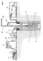
- a device 1 for cleaning wells 2, which for Promotion of drinking or industrial water, includes one cleaning unit 4 which can be lowered into a well shaft 3, whose ultrasound generator 5, for example, by one Cable reel 6 unwinding, live cable 7 with electricity is supplied.
- a power generator is also provided for this purpose 8 and a generator 9 and a switching device 10, which are connected via live cables 11.
- the accruing Dirty water is pumped out via a pipe rod 12 and collected, for example, in a settling tank 13 or cleaned.
- a lifting device 14 with cables 15 is used for lowering and gradually moving the cleaning unit 4 and to catch up after cleaning.
- the fountain 2 comprises to delimit the well shaft 3 a well wall 16, which is at the level of the water-carrying Has layers of openings 17. On the outside the well wall 16 is usually one Gravel layer 18 which merges into grown soil 19.
- the cleaning unit 4 comprises according to FIG. 2 at the lower end of the pipe string 12, a dirty water pump 19 'and one Ultrasound generator 5, not shown, which is expedient arranged below the dirty water pump 19 ' is.
- the ultrasound generator 5 generally comprises at least two and preferably several, also optionally in several Levels 20, 21 and 22 ultrasonic transducers arranged one below the other 23. With the help of an adjustment device 24 are the ultrasonic vibrators 23 on the respective Diameter of the well shaft 3 and at an optimal distance adjustable to the well wall 16. Also spacers 25 for example in the form of rolls can be provided be a precisely defined distance between each sound radiating surface 26 of each ultrasonic transducer 23 and the inside of the well wall 16 or ensure the openings 17 located there.
- the ultrasonic vibrators 23 at one arranged in cross section for example U-shaped carrier 27, which is parallel to axis 28 of the well shaft 3 extends.
- the carriers 27 are more suitable with the help Bearings 28 'also serve as spacers 25 attached.
- the ultrasonic vibrators 23 are in resonance frequency Longitudinally vibrating, high-alloy nickel sheet packages and are so with their sound-radiating surfaces 26 the fountain wall 16 facing the ultrasonic waves from the shortest possible distance and perpendicular to the inside 29 of the well wall 16 or onto the openings 17 meet and then behind the openings 17 in the area the gravel layer 18 have a cleaning effect.
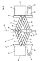
- each parallel link 30, 30 'or 31, 31' comprises the adjusting device 24 according to that shown in FIG. 3 Embodiment each parallel link 30, 30 'or 31, 31'.
- Each pair of parallel links 30, 30 ' or 31, 31 ' which are arranged V-shaped to each other on the one hand articulated on the supports 27 and with the others Ends of those directed downward by the ultrasonic vibrators 23
- Threaded rod 33 with the well axis 28 aligned or coaxial to the sleeve 32 is provided and extends through and is with one end at the lower end of the dirty water pump 19 'rotatably mounted and can at its other end for example, be provided with a hand crank 34.
- the Threaded rod 33 with the hand crank 34 is used for adjustment the ultrasonic vibrator 23 according to the respective Well wall diameter 16.
- To the sleeve 32 also has a sufficiently large elongated hole 36 on, so that the linkage of the handlebars 30 and 30 ' the adjusting nut 35 is possible and the elongated hole 36 also to achieve a sufficiently large setting range serves or must be suitable.
- the dirty water pump 19 'suction openings 37 only at their the end facing the ultrasonic vibrators 23.
- a seal 38 on the outside 29 to the inside of the well wall 16 provided. This has the consequence that the dirty water pump 19 'essentially only liquid from the Part of the well shaft 3, in which the Ultrasonic vibrator 23 are located.
- a second, similarly working seal 38 ' is located itself over the dirty water pump 19 '.
- the ultrasound transducer 23 is supplied with power via electrical cables 39 that run through the pump room extend downwards and over a suitable, waterproof coupling 40 with the live cable 7 are connected to the generator 9 or to the switching device 10 leads.
- Another current-carrying cable 41 with associated coupling 42 is provided according to FIG. 5 and supplies the Dirty water pump 19 'with electric current.
- the pipe link 12 carries the cleaning unit 4.
- the cleaning unit 4 For the operation of the cleaning unit 4 according to FIG. 5 is characteristic that the area of the Well shaft 3 is initially sonicated, whereupon the Dirty water is sucked off. Then the whole Cleaning unit 4 by one step or work cycle proceed below.
- Fig. 6 shows a modified embodiment, wherein basically same parts the same reference numbers and additionally have the letter index a.
- the cleaning unit 4a is correct with regard to the ultrasound generator 5a substantially identical to that described first Embodiment match. There are differences only with regard to the dirty water pump 19a 'and in terms of how it works.
- the dirty water pump 19a ' has its entire length Intake openings 37a. These suction openings are also located 37a between a lower seal 38a and one upper seal 38a ', each of the dirty water pump 19a 'or their suction openings 37a with respect to the inside 29a of the well wall 16a largely seal.
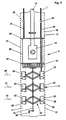
- FIG. 7 Another embodiment of an ultrasound generator is shown in Figures 7 and 8, wherein same parts the same reference numbers and additionally the Have letter index b.
- the ultrasound generator 5b is not provided with an adjustment device for the individual ultrasonic vibrators 23b, 23b ' or 23b '', but it has guide devices 50b so that the ultrasonic transducers on the respective The diameter of the well is set in the radial direction can be.
- Each guide device 50b comprises itself radially and parallel arms 51b and 52b.
- Arms 51b and 52b are double arms and extend according to the exemplary embodiment radially the same in each case from the well axis 28b far outwards.
- the Ultrasonic generator 23b, 23b 'and 23b' ' are expediently in housings 53b and are via this housing 53b directly on the arms 51b and 52b attached.
- suitable Fastening means 56b for example in the form of Threaded bolts and nuts are used to fix the ultrasonic transducers 23b and its housing 53b along and between the arms 51b and 52b of the respective guide device 50b.
- connection elements serving intermediate pieces 57b and connecting flanges 58b an assembly 59b.
- connection flanges 58b With their aligned connection flanges 58b and with the help of fasteners 60b, several units 59b become an ultrasound generator 5b composed.
- Fig. 4 for the embodiment shown there and Figures 7 and 8 for the last described Show embodiment are the ultrasonic transducers 23b basically arranged in a star shape.
- Each ultrasonic transducer brushes with the ones it emits Sound waves an area that is significantly larger than its sound radiating surface 26b. By their arrangement ensures that there is no sonication.
- An intermediate piece 57b and 52b is associated with each arm 51b and 52b a connecting flange 58b. Between arms 51b and 52b are only the radially adjustable ones for space reasons Ultrasonic vibrator 23b arranged. This leads to they also back to back between arms 51b and 52b are adjustable when it comes to a well shaft to clean with the smallest possible diameter. This is just then reachable if only two ultrasonic transducers at a time 23b in a plane 20b or 21b or 22b diametrically to one another are arranged and otherwise in an axial distance from each other.
Landscapes
- Engineering & Computer Science (AREA)
- Geology (AREA)
- Life Sciences & Earth Sciences (AREA)
- Mining & Mineral Resources (AREA)
- Environmental & Geological Engineering (AREA)
- Fluid Mechanics (AREA)
- Physics & Mathematics (AREA)
- General Life Sciences & Earth Sciences (AREA)
- Geochemistry & Mineralogy (AREA)
- Mechanical Engineering (AREA)
- Cleaning By Liquid Or Steam (AREA)
- Automatic Analysis And Handling Materials Therefor (AREA)
- Cleaning In General (AREA)
Description
- Fig. 1:
- eine Prinzipskizze mit verschiedenen Komponenten, die zum Reinigen eines Brunnens mit Hilfe von Ultraschall erforderlich sind;
- Fig. 2:
- in größerem Maßstab sowie im Schnitt eine Prinzipskizze einer mit Ultraschall arbeitenden Reinigungseinheit in einem Brunnen;
- Fig. 3:
- eine Einzelheit des Ultraschallerzeugers in Seitenansicht in nochmals größerem Maßstab;
- Fig. 4:
- eine Draufsicht auf den Ultraschallerzeuger in nochmals anderem Maßstab;
- Fig. 5:
- eine Prinzipskizze einer Reinigungseinheit entsprechend Fig. 2 in kleinerem Maßstab;
- Fig. 6:
- eine Prinzipskizze wie in Fig. 5 von einer abgewandelten Ausführungsform;
- Fig. 7:
- in größerem Maßstab eine Prinzipskizze einer weiteren Ausführungsform eines Ultraschallerzeugers und
- Fig. 8:
- eine Draufsicht auf den Ultraschallerzeuger längs der Schnittlinie VIII-VIII in Fig. 7.
Claims (9)
- Vorrichtung zum Reinigen von Brunnen (2) mit Hilfe von Ultraschall sowie mit mindestens einem magnetostriktiv arbeitenden Ultraschallschwinger (23, 23b), gekennzeichnet durcha) eine Leistung von acht bis zwölf Watt pro Quadratzentimeter (cm2) schallstrahlender Fläche (26, 26b) sowieb) mindestens eine Verstelleinrichtung (24) oder mindestens eine Führungseinrichtung (50b) derart,c) dass der/die Ultraschallschwinger (23, 23b) mit Hilfe der Verstelleinrichtung (24)/Führungseinrichtung (50b) quer zur Brunnenachse (28, 28b) einstellbar ist sind.
- Vorrichtung nach Anspruch 1, dadurch gekennzeichnet, dass ein Ultraschallerzeuger (5) mit mindestens zwei Ultraschallschwingern (23) in mindestens einer Ebene (20, 21, 22) vorgesehen ist.
- Vorrichtung nach einem oder mehreren der vorhergehenden Ansprüche, dadurch gekennzeichnet, dass die Ultraschallschwinger (23, 23b) sternförmig angeordnet sind.
- Vorrichtung nach einem oder mehreren der vorhergehenden Ansprüche, dadurch gekennzeichnet, dass die Ultraschallschwinger (23, 23b) in mehreren Ebenen (20, 20b bzw. 21, 21b bzw. 22, 22b) angeordnet sind.
- Vorrichtung nach einem oder mehreren der vorhergehenden Ansprüche, dadurch gekennzeichnet, dass jeweils zwei Ultraschallschwinger (23, 23b) in einer Ebene (20, 20b bzw. 21, 21b bzw. 22, 22b) diametral zueinander angeordnet sind.
- Vorrichtung nach Anspruch 1, dadurch gekennzeichnet, dass die Führungseinrichtung (50b) Langlöcher (54b, 55b) aufweist.
- Vorrichtung nach Anspruch 1 und 6, dadurch gekennzeichnet dass die Führungseinrichtung (50b) sich radial sowie parallel erstreckende Arme (51b, 52b) umfaßt.
- Vorrichtung nach Anspruch 1 und einem oder mehreren der vorhergehenden Ansprüche, dadurch gekennzeichnet, dass die Ultraschallschwinger (23b) jeweils zwischen zwei Armen (51b, 52b) angeordnet sind.
- Vorrichtung nach einem oder mehreren der vorhergehenden Ansprüche, dadurch gekennzeichnet, dass die Ultraschallschwinger (23b) einer Ebene (20b, 21b, 22b) und die zugehörigen Arme (51b, 52b) zusammen mit Anschlußelementen jeweils eine Baueinheit (59b) bilden.
Priority Applications (1)
| Application Number | Priority Date | Filing Date | Title |
|---|---|---|---|
| US08/621,815 US5727628A (en) | 1995-03-24 | 1996-03-22 | Method and apparatus for cleaning wells with ultrasonics |
Applications Claiming Priority (2)
| Application Number | Priority Date | Filing Date | Title |
|---|---|---|---|
| DE19510421 | 1995-03-24 | ||
| DE19510421 | 1995-03-24 |
Publications (3)
| Publication Number | Publication Date |
|---|---|
| EP0733779A2 EP0733779A2 (de) | 1996-09-25 |
| EP0733779A3 EP0733779A3 (de) | 1997-10-22 |
| EP0733779B1 true EP0733779B1 (de) | 2002-12-18 |
Family
ID=7757389
Family Applications (1)
| Application Number | Title | Priority Date | Filing Date |
|---|---|---|---|
| EP96101406A Expired - Lifetime EP0733779B1 (de) | 1995-03-24 | 1996-02-01 | Verfahren und Vorrichtung zum Reinigen von Brunnen mit Hilfe von Ultraschall |
Country Status (3)
| Country | Link |
|---|---|
| EP (1) | EP0733779B1 (de) |
| AT (1) | ATE230062T1 (de) |
| DE (1) | DE59609982D1 (de) |
Cited By (1)
| Publication number | Priority date | Publication date | Assignee | Title |
|---|---|---|---|---|
| CN112627779A (zh) * | 2020-12-21 | 2021-04-09 | 耐尔能源装备有限公司 | 一种潜油电泵防垢缓蚀装置 |
Families Citing this family (5)
| Publication number | Priority date | Publication date | Assignee | Title |
|---|---|---|---|---|
| DE19547264A1 (de) * | 1995-12-07 | 1997-06-12 | Dankwart Klein Erdbohrungen Gm | Verfahren und Vorrichtung zur Erhaltung der Leistungsfähigkeit neuer Brunnen sowie zur Reinigung und Regenerierung bestehender Brunnen mittels Ultraschall |
| DE29711422U1 (de) * | 1997-07-01 | 1997-09-04 | Erdmann, Peter, 58640 Iserlohn | Anordnung zur Regenerierung verockerter Trinkwasserbrunnen |
| DE202019100359U1 (de) | 2018-01-31 | 2019-02-27 | sonic technologies GmbH | Vorrichtung zur Emission von Ultraschall |
| RU2739170C1 (ru) * | 2020-04-20 | 2020-12-21 | Николай Борисович Болотин | Устройство для очистки скважинного фильтра |
| CN117266838B (zh) * | 2023-11-01 | 2025-08-22 | 上海瑞达峰致能源科技股份有限公司 | 一种探测煤层气井井底沉淀物厚度的装置 |
Family Cites Families (4)
| Publication number | Priority date | Publication date | Assignee | Title |
|---|---|---|---|---|
| SU1214863A2 (ru) * | 1984-06-22 | 1986-02-28 | Ивано-Франковский Институт Нефти И Газа | Устройство дл очистки фильтров эксплуатируемых на воду скважин |
| EP0225113A3 (de) * | 1985-11-19 | 1988-12-14 | Westinghouse Electric Corporation | Magnetostriktives Wandlergerät |
| US5184678A (en) * | 1990-02-14 | 1993-02-09 | Halliburton Logging Services, Inc. | Acoustic flow stimulation method and apparatus |
| NL9320035A (nl) * | 1992-06-03 | 1995-05-01 | Mobil Oil Corp | Werkwijze voor het verwijderen van alkalimetaalsulfaat-bevattende afzetting. |
-
1996
- 1996-02-01 AT AT96101406T patent/ATE230062T1/de not_active IP Right Cessation
- 1996-02-01 DE DE59609982T patent/DE59609982D1/de not_active Expired - Fee Related
- 1996-02-01 EP EP96101406A patent/EP0733779B1/de not_active Expired - Lifetime
Cited By (2)
| Publication number | Priority date | Publication date | Assignee | Title |
|---|---|---|---|---|
| CN112627779A (zh) * | 2020-12-21 | 2021-04-09 | 耐尔能源装备有限公司 | 一种潜油电泵防垢缓蚀装置 |
| CN112627779B (zh) * | 2020-12-21 | 2021-07-20 | 耐尔能源装备有限公司 | 一种潜油电泵防垢缓蚀装置 |
Also Published As
| Publication number | Publication date |
|---|---|
| EP0733779A2 (de) | 1996-09-25 |
| ATE230062T1 (de) | 2003-01-15 |
| EP0733779A3 (de) | 1997-10-22 |
| DE59609982D1 (de) | 2003-01-30 |
Similar Documents
| Publication | Publication Date | Title |
|---|---|---|
| DE10310543B4 (de) | Wafer-Reinigungssystem und Verfahren zum Reinigen eines Wafers | |
| DE2913807C2 (de) | ||
| DE69202452T2 (de) | Anordnung für das mit ultraschall erschüttern einer nichtresonierender struktur. | |
| DE3523603C2 (de) | Bahnschneidvorrichtung | |
| EP0733779B1 (de) | Verfahren und Vorrichtung zum Reinigen von Brunnen mit Hilfe von Ultraschall | |
| DE4004711A1 (de) | Verfahren und vorrichtung zur entfernung von schadstoffen aus untergrund-formationen im erdboden | |
| DE2641830A1 (de) | Verfahren und vorrichtung zur entfernung von schmutzstoffen im wasser durch ultraschall | |
| DE3635968A1 (de) | Resonator mit gleichmaessiger ausgangsschwingungsamplitude | |
| WO1991012409A1 (de) | Verfahren und vorrichtung zur beseitigung von inkrustierungen in form von verockerung und/oder versinterung in brunnen | |
| DE10317329A1 (de) | Vorrichtung und Verfahren zum Reinigen eines Halbleiterwafers | |
| EP3521215B1 (de) | Schwingförderer | |
| DE69426067T2 (de) | Einrichtung zur abschreckung von tierischen schädlingen mittels ultraschall und verfahren zu deren herstellung | |
| EP0431431B1 (de) | Rakeleinrichtung | |
| DE19647482A1 (de) | Ultraschall-Reinigungsvorrichtung | |
| DE3920800C1 (en) | Detoxifying soil in-situ - by introducing cleansing medium and vibrating using cylindrical chamber with 3 radial plate carrying tubes | |
| DE19547264A1 (de) | Verfahren und Vorrichtung zur Erhaltung der Leistungsfähigkeit neuer Brunnen sowie zur Reinigung und Regenerierung bestehender Brunnen mittels Ultraschall | |
| DE3611235C1 (de) | Entwaesserungsmaschine | |
| DE102005012244B4 (de) | Verfahren zur Reinigung von Gegenständen mittels Ultraschall | |
| EP1514652A2 (de) | Lebensmittelschneidvorrichtung mit einem Schneidmittel mit einem Schwingungsgenerator | |
| DE4138713A1 (de) | Mehrfrequenz-ultraschallschwinger | |
| WO1990009834A1 (de) | Vorrichtung zum abziehen von boden- oder schwimmschlamm aus einem klärbecken oder dergleichen | |
| DE3739184C2 (de) | Unterwasser-Schleppantenne | |
| CH700441A1 (de) | Vibrationswendelförderer zum Entstauben und Entgraten von Kleinteilen. | |
| DE19724189C2 (de) | Rohrförmige elektroakustische Vorrichtung zur Erzeugung von Ultraschallenergie | |
| DE69302906T2 (de) | Vorrichtung und verfahren zum herstellen von bauelementen aus beton |
Legal Events
| Date | Code | Title | Description |
|---|---|---|---|
| PUAI | Public reference made under article 153(3) epc to a published international application that has entered the european phase |
Free format text: ORIGINAL CODE: 0009012 |
|
| AK | Designated contracting states |
Kind code of ref document: A2 Designated state(s): AT BE CH DE DK ES FR GB IT LI NL |
|
| PUAL | Search report despatched |
Free format text: ORIGINAL CODE: 0009013 |
|
| AK | Designated contracting states |
Kind code of ref document: A3 Designated state(s): AT BE CH DE DK ES FR GB IT LI NL |
|
| 17P | Request for examination filed |
Effective date: 19980422 |
|
| 17Q | First examination report despatched |
Effective date: 19991014 |
|
| GRAG | Despatch of communication of intention to grant |
Free format text: ORIGINAL CODE: EPIDOS AGRA |
|
| GRAG | Despatch of communication of intention to grant |
Free format text: ORIGINAL CODE: EPIDOS AGRA |
|
| GRAH | Despatch of communication of intention to grant a patent |
Free format text: ORIGINAL CODE: EPIDOS IGRA |
|
| GRAH | Despatch of communication of intention to grant a patent |
Free format text: ORIGINAL CODE: EPIDOS IGRA |
|
| GRAA | (expected) grant |
Free format text: ORIGINAL CODE: 0009210 |
|
| AK | Designated contracting states |
Kind code of ref document: B1 Designated state(s): AT BE CH DE DK ES FR GB IT LI NL |
|
| PG25 | Lapsed in a contracting state [announced via postgrant information from national office to epo] |
Ref country code: NL Free format text: LAPSE BECAUSE OF FAILURE TO SUBMIT A TRANSLATION OF THE DESCRIPTION OR TO PAY THE FEE WITHIN THE PRESCRIBED TIME-LIMIT Effective date: 20021218 Ref country code: IT Free format text: LAPSE BECAUSE OF FAILURE TO SUBMIT A TRANSLATION OF THE DESCRIPTION OR TO PAY THE FEE WITHIN THE PRE;WARNING: LAPSES OF ITALIAN PATENTS WITH EFFECTIVE DATE BEFORE 2007 MAY HAVE OCCURRED AT ANY TIME BEFORE 2007. THE CORRECT EFFECTIVE DATE MAY BE DIFFERENT FROM THE ONE RECORDED.SCRIBED TIME-LIMIT Effective date: 20021218 Ref country code: GB Free format text: LAPSE BECAUSE OF FAILURE TO SUBMIT A TRANSLATION OF THE DESCRIPTION OR TO PAY THE FEE WITHIN THE PRESCRIBED TIME-LIMIT Effective date: 20021218 Ref country code: FR Free format text: LAPSE BECAUSE OF FAILURE TO SUBMIT A TRANSLATION OF THE DESCRIPTION OR TO PAY THE FEE WITHIN THE PRESCRIBED TIME-LIMIT Effective date: 20021218 |
|
| REF | Corresponds to: |
Ref document number: 230062 Country of ref document: AT Date of ref document: 20030115 Kind code of ref document: T |
|
| REG | Reference to a national code |
Ref country code: GB Ref legal event code: FG4D Free format text: NOT ENGLISH |
|
| REG | Reference to a national code |
Ref country code: CH Ref legal event code: EP |
|
| REF | Corresponds to: |
Ref document number: 59609982 Country of ref document: DE Date of ref document: 20030130 Kind code of ref document: P Ref document number: 59609982 Country of ref document: DE Date of ref document: 20030130 |
|
| PG25 | Lapsed in a contracting state [announced via postgrant information from national office to epo] |
Ref country code: AT Free format text: LAPSE BECAUSE OF NON-PAYMENT OF DUE FEES Effective date: 20030201 |
|
| PG25 | Lapsed in a contracting state [announced via postgrant information from national office to epo] |
Ref country code: LI Free format text: LAPSE BECAUSE OF NON-PAYMENT OF DUE FEES Effective date: 20030228 Ref country code: CH Free format text: LAPSE BECAUSE OF NON-PAYMENT OF DUE FEES Effective date: 20030228 Ref country code: BE Free format text: LAPSE BECAUSE OF NON-PAYMENT OF DUE FEES Effective date: 20030228 |
|
| PG25 | Lapsed in a contracting state [announced via postgrant information from national office to epo] |
Ref country code: DK Free format text: LAPSE BECAUSE OF FAILURE TO SUBMIT A TRANSLATION OF THE DESCRIPTION OR TO PAY THE FEE WITHIN THE PRESCRIBED TIME-LIMIT Effective date: 20030318 |
|
| GBV | Gb: ep patent (uk) treated as always having been void in accordance with gb section 77(7)/1977 [no translation filed] |
Effective date: 20021218 |
|
| PG25 | Lapsed in a contracting state [announced via postgrant information from national office to epo] |
Ref country code: ES Free format text: LAPSE BECAUSE OF FAILURE TO SUBMIT A TRANSLATION OF THE DESCRIPTION OR TO PAY THE FEE WITHIN THE PRESCRIBED TIME-LIMIT Effective date: 20030627 |
|
| REG | Reference to a national code |
Ref country code: CH Ref legal event code: PL |
|
| PLBE | No opposition filed within time limit |
Free format text: ORIGINAL CODE: 0009261 |
|
| STAA | Information on the status of an ep patent application or granted ep patent |
Free format text: STATUS: NO OPPOSITION FILED WITHIN TIME LIMIT |
|
| EN | Fr: translation not filed | ||
| 26N | No opposition filed |
Effective date: 20030919 |
|
| PGFP | Annual fee paid to national office [announced via postgrant information from national office to epo] |
Ref country code: DE Payment date: 20040420 Year of fee payment: 9 |
|
| PG25 | Lapsed in a contracting state [announced via postgrant information from national office to epo] |
Ref country code: DE Free format text: LAPSE BECAUSE OF NON-PAYMENT OF DUE FEES Effective date: 20050901 |