EP0733828A2 - Transducteur de mouvement - Google Patents
Transducteur de mouvement Download PDFInfo
- Publication number
- EP0733828A2 EP0733828A2 EP96301986A EP96301986A EP0733828A2 EP 0733828 A2 EP0733828 A2 EP 0733828A2 EP 96301986 A EP96301986 A EP 96301986A EP 96301986 A EP96301986 A EP 96301986A EP 0733828 A2 EP0733828 A2 EP 0733828A2
- Authority
- EP
- European Patent Office
- Prior art keywords
- core
- housing
- groove
- displacement
- operative position
- Prior art date
- Legal status (The legal status is an assumption and is not a legal conclusion. Google has not performed a legal analysis and makes no representation as to the accuracy of the status listed.)
- Withdrawn
Links
Images



Classifications
-
- F—MECHANICAL ENGINEERING; LIGHTING; HEATING; WEAPONS; BLASTING
- F16—ENGINEERING ELEMENTS AND UNITS; GENERAL MEASURES FOR PRODUCING AND MAINTAINING EFFECTIVE FUNCTIONING OF MACHINES OR INSTALLATIONS; THERMAL INSULATION IN GENERAL
- F16H—GEARING
- F16H25/00—Gearings comprising primarily only cams, cam-followers and screw-and-nut mechanisms
- F16H25/18—Gearings comprising primarily only cams, cam-followers and screw-and-nut mechanisms for conveying or interconverting oscillating or reciprocating motions
- F16H25/186—Gearings comprising primarily only cams, cam-followers and screw-and-nut mechanisms for conveying or interconverting oscillating or reciprocating motions with reciprocation along the axis of oscillation
Definitions
- This invention relates to motion transducers, more particularly to devices for producing rapid angular displacements about an axis in response to thrust exerted along the said axis.
- the device according to the invention has a number of industrial applications, for instance actuating a safety valve or other safety devices in response to an increase of pressure within a container, causing a cam quickly to pass from one side of a dead point to another, and the like.
- the device according to the invention is characterized in that it comprises, in combination, a housing having a cylindrical bore therein; a core of an essentially cylindrical shape, fitting into said bore of said housing and axially and angularly displaceable with respect thereto, in response to an axial thrust, between an inoperative condition and an operative position, said core being provided on its surface with at least one groove and preferably a plurality of grooves, having a substantially helicoidal portion; and a guide member for each of said grooves, said guide member projecting into said cylindrical bore and engaging said groove; said core further having means for actuating, when displaced to its operative position, any desired device (hereinafter referred to as "controlled device").
- Means are provided for preventing displacement of said core in a direction opposite to that of its displacement from said inoperative position to said operative position, said means preferably comprising a closed, substantially rectilinear, terminal axial portion of said groove or grooves.
- Means are preferably provided in the device for preventing said core from being displaced beyond said operative position, and these means may either limit the axial or the angular displacement of said core. thus providing self-locking properties.
- Means are provided in said core for receiving an axial thrust. which means preferably consist in a surface preferably provided at one end of said core.
- the means for actuating, when said core is displaced to its operative position, the controlled device preferably comprise an arm carried by the core at or in the vicinity of one end, preferably the end opposite to that at which the thrust receiving surface is provided, if such is provided.
- the controlled device is not part of the invention and may be of any desired kind, as long as it can be actuated by the angular displacement of said core.
- the guide members may be a part of the housing, but in a preferred embodiment of the device they are attachable to it in fixed positioned relationship, and still more preferably they are pins that can be inserted into seats of the housing.
- said seats are radial seats opening into the cylindrical bore of the housing.
- said radial seats are cylindrical, the portion of each of said pins inserted in the corresponding seat is cylindrical, and the portion of each of said pins engaging the corresponding groove of said core is bounded by convex arcuate surfaces.
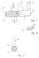
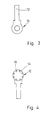
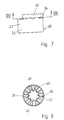
- the device according to the invention comprises a core 10 (separately illustrated in Figs. 1-4) and a housing 20 (separately illustrated in Figs. 5-8).
- Core 10 comprises a substantially cylindrical portion 11 and an arm 12. This latter may have any desired shape and the shape shown in the figures has no particular significance.
- the terminal surface of core 11, indicated at 14, at the opposite end of arm 12 is a thrust surface, as will later be better explained.
- Cylindrical portion 11 has defined therein grooves 13, which in the examples shown are in the number of eight, but may be in any desired number and even be a single one. One of said grooves is visible in its entirety in Fig. 1 and its configuration can thus be understood.
- the initial portion of any groove 13, starting from first surface 14, is rectilinear or substantially rectilinear. That portion is indicated in Fig. 1 by numeral 15. It is followed by a substantially helical or helicoidal portion 16 with a shoulder 18, as shown in the detail of Fig. 1a.
- the portion 17 of groove 13 adjacent to shoulder 18 is essentially rectilinear but may be very short, and might in fact be missing altogether, the axis of the groove being merely tangent to the axial direction in the vicinity of shoulder 18.
- Grooves 13 have a substantially rectangular cross-section, as shown in Fig. 2, but this is not necessary, and the shape of said cross-section might be changed if desired.
- the housing 20 comprises a substantially cylindrical body 21, which may be attached in any convenient way to any frame or support.
- the means for attaching it are indicated as a lateral projection 22, shown as broken off at 23, since it may have any desired configuration and be attached by any desired means to a frame or support.
- the cylindrical portion 21 is provided with seats for guide members adapted to engage grooves 13 of core 11 and guide said core in its displacement.
- said guide members are pins 30, illustrated in Figs. 13 to 15.
- the said seats of said core 20 are circular bores as shown in Fig.
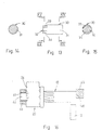
- the pins 30 have a cylindrical portion 31, which can be seated in bore 24 and freely rotate therein, and a shaped portion 32, which protrudes within the cylindrical space enclosed by the inner surface 25 of housing 20 and engages a groove 13 and is illustrated in cross-section in Fig. 14.
- said portion 32 is bound by two arcuate surfaces 33-34. It is desirable that the radius of curvature of said surfaces be as high as possible, preferably substantially greater then d/2, wherein d is the diameter of the cylindrical portion 31 of the pin, this in order to minimize the pressure stressses between pin and groove 13, at the point of contact, viz. at the center of the arcuate surfaces 33-34.
- Means are provided for retaining pins 30 within bores 24, and, in the embodiment illustrated, they consist of a ring 40, which can be slipped onto the cylindrical portion 21 of housing 20 in such a way as to cover bores 24 at least partially.
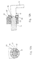
- Core 10 is displaceable within housing 20 from an inoperative and an operative position.
- the inoperative position is shown in Figs. 9, 10, 12a and 12b.
- core 10 is inserted within the circular opening of housing 20, its outer surface slideably engages the inner surface 25 of said space, pins 30 are inserted in the bores 24 of said housing and the shaped portions 32 thereof are engaged with grooves 13.
- the core is inserted into housing 20 as far as it will go. viz. until pins 30 engage shoulders 18 of grooves 13 and prevent any further displacement in the direction indicated by the arrow A of Fig. 9. In this position the pins 30 engage terminal portion 17 of grooves 13 and shoulders 18.
- any moment or tangential thrust exerted on arm 12 will produce no rotation of the core and no displacement of the device.
- core 10 will be displaced axially in a direction opposite to that of arrow A in Fig. 9.
- grooves 13 will slide over arcuate surfaces 33-34 of shaped portions 32 of pins 30. While it would be possible to dispense with such shaped portions and make the pins entirely cylindrical, with a diameter small enough so that they will fit into grooves 13, it is desirable to shape them as described . While grooves 13 slide over portions 32 of pins 30, the pins will rotate to follow the slant of the grooves, and this is permitted by the cylindrical configurations of portions 31 of pins 30 and of bores 24 of housing 11.
- Fig. 11 Once core 10 reaches the operative position of Fig. 11, it will be prevented from becoming further displaced in the same direction by any suitable means that may be provided.
- Two such means are schematically indicated in Fig.16, but they have no particular significance, since they can be replaced by any other mechanical means easily devised by persons skilled in the art. In fact, said means may be omitted altogether, since the controlled device itself may be such as to prevent any displacement beyond the operative position.
- One of the means schematically shown consists of a ring 43 which may be applied, e.g.
- a terminal extension 42 of core 10 (not shown in any of the other figures, as it will generally be lacking) which extends beyond the threaded portion 15 of core 10, once the core has been inserted into housing 20.
- Ring 43 will bear against surface 26 of housing 20 and prevent any further displacement of the core.
- Another means. shown for economy of illustration in the same figure, consists of a stop member 45, schematically illustrated, against which the surface 19 of core 10, which is the end surface of the core on the side of arm 12, will bear, to prevent any further displacement.
- core 10 In passing from the inoperative position of Fig. 9 to the operative position of Fig. 11, core 10 will have become angularly displaced by an angle that is measured by the arc on the periphery of core 10 between portions 15 and 17 of the grooves.
- This angle is illustrated in Fig. 17, wherein a single groove is shown in an end view of the core and the angular position of said groove when the core is in the position of Fig. 9 is shown in full lines while its position is as shown in Fig. 17 in broken lines.
- Said angle is indicated by ⁇ 1 .
- Said angular displacement occurs in the time in which the pins 30 are in engagement with the intermediate, helicoidal portions 16 of grooves 13.
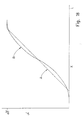
- Fig. 18 The kinematics of the rotation of core 10 are illustrated in Fig. 18. It will be clear that if the angle ⁇ 1 by which the core rotates between its two extreme positions, were 360°, then the axial length of the helicoidal portion 16 of the grooves 13 would be equal to their pitch. Since said portions generally are not perfectly helical, the pitch to be considered is that of a perfect helix the initial and terminal points of which are the same as the initial and terminal points of said portions, viz. the average pitch of the actual helix of the device. The angle ⁇ 1 therefore is equal to 2 ⁇ L/p, wherein L is the axial length of the helical portion 16 of a groove 13, and p is said average pitch.
- ⁇ is the angle by which the core has rotated from its initial position
- ⁇ is the angle between the tangent to the center line of the portions 16 and the axial direction of the core 10
- x is the axial displacement of the core and R its radius.
- tg ⁇ R.d ⁇ /dx. Therefore, if the portions 16 were perfectly helical, viz. the angle ⁇ were constant, the angle ⁇ would be proportional to the axial displacement and the rotation of the core would be represented by the broken line A in Fig. 18, wherein the abscissa is x and the ordinate is ⁇ . In the first part of the movement, when the pins 30 are in engagement with the portion 15 of the grooves 13, ⁇ remains equal to zero.
- the admissible speed of rotation depends mainly on the capability of the device to stand the stresses due to shock which arise at the end of its displacement, when it is stopped.
Landscapes
- Engineering & Computer Science (AREA)
- General Engineering & Computer Science (AREA)
- Mechanical Engineering (AREA)
- Molds, Cores, And Manufacturing Methods Thereof (AREA)
Applications Claiming Priority (2)
| Application Number | Priority Date | Filing Date | Title |
|---|---|---|---|
| IL11310595 | 1995-03-23 | ||
| IL11310595A IL113105A0 (en) | 1995-03-23 | 1995-03-23 | Motion transducer |
Publications (2)
| Publication Number | Publication Date |
|---|---|
| EP0733828A2 true EP0733828A2 (fr) | 1996-09-25 |
| EP0733828A3 EP0733828A3 (fr) | 1997-01-15 |
Family
ID=11067259
Family Applications (1)
| Application Number | Title | Priority Date | Filing Date |
|---|---|---|---|
| EP96301986A Withdrawn EP0733828A3 (fr) | 1995-03-23 | 1996-03-22 | Transducteur de mouvement |
Country Status (2)
| Country | Link |
|---|---|
| EP (1) | EP0733828A3 (fr) |
| IL (1) | IL113105A0 (fr) |
Cited By (1)
| Publication number | Priority date | Publication date | Assignee | Title |
|---|---|---|---|---|
| EP1772648A1 (fr) * | 2005-10-07 | 2007-04-11 | Vrije Universiteit Brussel | Mecanisme comportant un corps de forme hélicoidale déroulant sur un corps de forme hyperboloïde |
Family Cites Families (5)
| Publication number | Priority date | Publication date | Assignee | Title |
|---|---|---|---|---|
| US3141387A (en) * | 1962-05-08 | 1964-07-21 | Gen Motors Corp | Twin piston rotary actuators |
| US3298659A (en) * | 1962-12-21 | 1967-01-17 | Cupedo Douwe Janse | Fluid power actuated butterfly valve or plug cock |
| FR1452166A (fr) * | 1965-07-24 | 1966-02-25 | Unité rotative à angle prédéterminé | |
| HU177203B (en) * | 1977-10-26 | 1981-08-28 | Epitoegepgyarto Vallalat | Working roll |
| DE8707252U1 (de) * | 1987-05-20 | 1987-11-12 | Hanel, Eugen, 4100 Duisburg | Gewindeform für einen Drehtrieb |
-
1995
- 1995-03-23 IL IL11310595A patent/IL113105A0/xx unknown
-
1996
- 1996-03-22 EP EP96301986A patent/EP0733828A3/fr not_active Withdrawn
Cited By (2)
| Publication number | Priority date | Publication date | Assignee | Title |
|---|---|---|---|---|
| EP1772648A1 (fr) * | 2005-10-07 | 2007-04-11 | Vrije Universiteit Brussel | Mecanisme comportant un corps de forme hélicoidale déroulant sur un corps de forme hyperboloïde |
| WO2007041813A1 (fr) * | 2005-10-07 | 2007-04-19 | Vrije Universiteit Brussel | Appareil comprenant un corps de forme helicoide roulant sur un corps de forme hyperboloide |
Also Published As
| Publication number | Publication date |
|---|---|
| EP0733828A3 (fr) | 1997-01-15 |
| IL113105A0 (en) | 1996-05-14 |
Similar Documents
| Publication | Publication Date | Title |
|---|---|---|
| EP0885164B1 (fr) | Dispositif d'actionnement de levier | |
| US4577730A (en) | Mechanical lock | |
| JP4402445B2 (ja) | 時計ケース | |
| US5934144A (en) | Split gear assembly for use in a worm gear drive | |
| US4570769A (en) | Ratchet mechanism | |
| EP0485620B1 (fr) | Retroviseur a telecommande electrique | |
| US6311576B1 (en) | Anti-backlash nut for lead screw | |
| JPH10511757A (ja) | バックラッシ除去ナットアセンブリ | |
| US4641737A (en) | Bi-directional overtravel stop | |
| CN116062021A (zh) | 用于线控转向转向系统的旋转限制组件和方向盘组件 | |
| US11047459B2 (en) | Ball screw device | |
| PL91172B1 (fr) | ||
| US7465248B2 (en) | Planetary gear type reduction gear with torque limiter | |
| EP3406936B1 (fr) | Mécanisme de vis planétaire amélioré | |
| US5765449A (en) | Spring locking and release apparatus for knobs and knob-like structures | |
| US5981940A (en) | Angle measuring system with a clampable shaft | |
| EP0733828A2 (fr) | Transducteur de mouvement | |
| JP4781808B2 (ja) | トルクリミッター付き遊星歯車型減速機 | |
| US5267759A (en) | Connector assembly | |
| US6546825B1 (en) | Actuator | |
| US5719712A (en) | Clicking device having a rotary member with teeth engageable with a plurality of fixed projections | |
| JPH10267062A (ja) | コイルスプリングのばね圧調整装置 | |
| US4721196A (en) | Overtravel stop | |
| EP0079184A1 (fr) | Roue dentée sans jeu divisée en deux parties opposées par des ressorts | |
| AU569210B2 (en) | Inertia stop for sudden loads |
Legal Events
| Date | Code | Title | Description |
|---|---|---|---|
| PUAI | Public reference made under article 153(3) epc to a published international application that has entered the european phase |
Free format text: ORIGINAL CODE: 0009012 |
|
| AK | Designated contracting states |
Kind code of ref document: A2 Designated state(s): AT BE CH DE DK ES FR GB IT LI NL SE |
|
| PUAL | Search report despatched |
Free format text: ORIGINAL CODE: 0009013 |
|
| AK | Designated contracting states |
Kind code of ref document: A3 Designated state(s): AT BE CH DE DK ES FR GB IT LI NL SE |
|
| STAA | Information on the status of an ep patent application or granted ep patent |
Free format text: STATUS: THE APPLICATION IS DEEMED TO BE WITHDRAWN |
|
| 18D | Application deemed to be withdrawn |
Effective date: 19970716 |