EP0733896A2 - Verfahren und Vorrichtung zur Bestimmung des Polymerisationsprofils einer Polymerschicht - Google Patents
Verfahren und Vorrichtung zur Bestimmung des Polymerisationsprofils einer Polymerschicht Download PDFInfo
- Publication number
- EP0733896A2 EP0733896A2 EP96104443A EP96104443A EP0733896A2 EP 0733896 A2 EP0733896 A2 EP 0733896A2 EP 96104443 A EP96104443 A EP 96104443A EP 96104443 A EP96104443 A EP 96104443A EP 0733896 A2 EP0733896 A2 EP 0733896A2
- Authority
- EP
- European Patent Office
- Prior art keywords
- radiation
- layer
- coating
- incidence
- intensity
- Prior art date
- Legal status (The legal status is an assumption and is not a legal conclusion. Google has not performed a legal analysis and makes no representation as to the accuracy of the status listed.)
- Granted
Links
Images
Classifications
-
- G—PHYSICS
- G01—MEASURING; TESTING
- G01N—INVESTIGATING OR ANALYSING MATERIALS BY DETERMINING THEIR CHEMICAL OR PHYSICAL PROPERTIES
- G01N33/00—Investigating or analysing materials by specific methods not covered by groups G01N1/00 - G01N31/00
- G01N33/44—Resins; Plastics; Rubber; Leather
- G01N33/442—Resins; Plastics
-
- G—PHYSICS
- G01—MEASURING; TESTING
- G01N—INVESTIGATING OR ANALYSING MATERIALS BY DETERMINING THEIR CHEMICAL OR PHYSICAL PROPERTIES
- G01N21/00—Investigating or analysing materials by the use of optical means, i.e. using sub-millimetre waves, infrared, visible or ultraviolet light
- G01N21/17—Systems in which incident light is modified in accordance with the properties of the material investigated
- G01N21/41—Refractivity; Phase-affecting properties, e.g. optical path length
- G01N21/412—Index profiling of optical fibres
Definitions
- the invention described herein relates to the characterisation of polymeric materials and in particular it concerns a method of and a device for determining the polymerisation profile of one such material.
- the invention can be applied to determination of the polymerisation profile of the polymeric coating of optical waveguides.
- the degree of polymerisation of a polymer determines many of its physical and mechanical characteristics, such as density, viscosity, refractive index, resistance to abrasion, response to tensile and flexure stresses, etc.
- the polymer is used as a coating, for instance as a protective coating, the knowledge of those characteristics is also important to know the behaviour of the coated body.
- optical waveguides with a coating, generally made of an acrylate, intended to prevent chemical attack of the waveguide and to improve its mechanical resistance to different kinds of stresses. It is essential that the characteristics of the coating remain constant in time, in order to guarantee a uniform behaviour of the guides, and therefore it is also necessary, to this end, to monitor the degree of polymerisation of the coating.
- the known devices essentially are spectrometers equipped with an accessory allowing the analysis of multiple reflections within a crystal. For the measurement, first a sample of non-polymerised resin is applied onto the crystal, its infrared spectrum is determined and the ratio U between the areas of an absorption peak which is not affected by polymerisation and of a peak that is affected by polymerisation is computed.
- a sample of the coating under test is fixed to the crystal, an infrared radiation is sent onto the sample at a pre-set angle such as to give rise to multiple reflections at the crystal-sample interface, and ratio BR between the areas of said peaks is computed both when contacting with the crystal the surface of the sample that was directly exposed to a polymerising radiation, and when contacting the opposite surface.
- the relative variation (U-BR)/U of those ratios provides the degree of polymerisation for the two faces of the coating.
- the known devices have the drawback of providing only information about the surfaces of the coating and not about its internal structure.
- the coatings of interest particularly for the preferred application, have relatively limited thickness, there is no guarantee that information about the surface should also be valid for the mass of the polymer.
- the measurement procedure is laborious, as it needs to be repeated for the two opposite surfaces of the material sample.
- the invention described herein provides instead a method and a device which allow the polymerisation profile of a coating (i.e. the behaviour of the degree of polymerisation throughout the entire thickness of the coating) to be determined with a single operation.
- a light radiation is sent towards the layer under test at different angles of incidence; both the portion of the radiation reflected by the layer and the portion transmitted are transformed into electrical signals; the intensities of said electrical signals are measured; the values of the reflectance and transmittance of the layer are obtained from said values of intensity; a value of the refractive index at a different depth inside the layer is obtained from the values of reflectance and transmittance relevant to each angle of incidence; and the degree of polymerisation at each depth is obtained by comparison with the values, determined in a calibration phase, of the refractive index of a precursor of the polymer and of the fully polymerised material.
- the device comprises: a light radiation source; means for sending that radiation towards a layer under test, at different angles of incidence; means for collecting and converting into electrical signals both the portion of radiation transmitted by the layer and the portion reflected by the layer; means for measuring the intensity of these electrical signals; a processing system arranged to: obtain the transmittance and reflectance of the layer at the different angles of incidence from the values of intensity; obtain a value of the refractive index at a different depth inside the layer from the values of reflectance and transmittance relevant to each angle of incidence; and to obtain the degree of polymerisation at each depth by comparison with the values, determined in a calibration phase and stored in the processing system, of the refractive index of a precursor of the polymer and of the fully polymerised polymeric material.
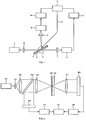
- the light emitted by a source 1, for instance a laser, is sent onto a sample 2 of the polymer to be analysed, possibly through an optical collimating system, represented schematically by lens 12.
- the sample is a very thin layer (e.g. 50 ⁇ m thick) applied on a glass plate 3.
- the sample is borne by a support, indicated schematically as 4, which allows the sample orientation with respect to the incident beam to be varied.
- the radiation transmitted and the radiation reflected by sample 2 are focused on detectors 5, 6, respectively, by means of optical systems represented schematically by lenses 7, 8.
- the electrical signals generated by detectors 5, 6 are supplied to intensity measuring devices 9, 10, which supply a processor 11 with the measured values of intensity.
- the processor also controls the support rotation, as depicted schematically by connection 13.
- the processor is arranged to: establish an association between the intensity information provided by detectors 5, 6 to the angle of incidence of the beam emitted by source 1; determine the values of reflectance and transmittance as the angle varies, starting from the intensity information; and obtain the polymerisation profile of the sample from the reflectance and transmittance values.
- the light emitted by source 101 is sent onto sample 102, mounted on plate 103, through an optical focusing system schematically represented by lenses 114, 115, 116.
- an optical collimating system schematically represented by lens 117 the light transmitted by sample 102 is collimated onto a linear detector array 105, where each detector receives the light refracted by sample 102 inside a certain range of angles.
- the light reflected by sample 102 is collected by lens 116 and collimated onto a semitransparent mirror 118, which is placed between lenses 115 and 116 and on one side transmits the light coming from source 101 towards lens 116 and sample 102, and on the other side reflects the light reflected by sample 102 towards a linear detector array 106, analogous to array 105.
- each detector in array 106 receives the radiation reflected by the sample within a certain range of angles. It is evident that the optical systems which allow the radiation transmitted or reflected by the sample to be transferred to the respective detectors must ensure a one-to-one correspondence between the detectors in both arrays.
- the detectors in arrays 105, 106 are connected to respective intensity measuring devices 109, 110, which in turn supply processor 111 with intensity information. As before, the processor establishes an association between the signals provided by the detectors and the angle of incidence, and then the polymerisation profile can be obtained starting from the measure of reflectance and transmittance as a function of the angle of incidence.
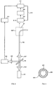
- source 201 launches light radiations into a length of coated optical fibre 200 through an optical system schematically represented by lenses 212, 207.
- Reference 202 indicates the polymeric coating and 203 the glass part (i. e. the bare fibre).
- Coated fibre 200 is mounted onto a support (not shown) which is so constructed that the fibre presents a curved region 200' with variable radius of curvature. In that region, the radiation guided in the fibre reaches the interface between glass part 203 and coating 202 with a variable angle of incidence, and a fraction of the radiation will exit through coating 202.
- That fraction is collected by a detector 205 which is placed on a support (incorporated in the detector itself to keep the drawing simple) which can be displaced parallel to itself in order to collect rays exiting different points of fibre region 200'.
- the displacements of the detector can be controlled by processor 211, as schematically shown by connection 213.
- detector 205 is associated with a device 209 measuring the intensity of the electrical signal generated by the detector itself, which device is connected to processor 211 associating intensity information with the position of the detector, and therefore with the angle of incidence of the radiation guided in the fibre on the glass-coating interface.
- a semi-transparent mirror 218 located between lenses 212 and 207 collects the radiation backscattered in the fibre and sends it, through an optical system 208, to a detector 206 associated with a device 210 measuring the intensity of the signals emitted by the detector.
- Measuring device 210 is a part, together with source 201, of a time domain reflectometry system which allows information on the intensity of the radiation backscattered to be associated with information on the point from which the radiation originated and therefore with the angle of incidence on the glass-coating interface.
- Also measuring device 210 is connected to processor 211 which, as in the previous embodiments, can determine transmittance and reflectance as a function of the angle of incidence and thus obtain the polymerisation profile.
- Transmittance in turn is linked to the values of the constants beyond the last layer. Since, as stated above, for each angle of incidence and for each layer transmittance and reflectance are known functions of n and k, by applying the relations reported in the article the processing system can immediately determine, for instance with the least squares method, the combination of pairs of values n, k which best fits the experimental data obtained for reflectance and transmittance. Once this combination of value pairs has been determined, the degree of polymerisation of the individual layer will be obtained by comparison with the corresponding values of n, k for the non-polymerised liquid and for the fully polymerised material.
- a calibration phase the profile of the complex refractive index for a layer, of the same thickness as the sample, of the polymer precursor liquid and for a fully polymerised layer.
- This calibration phase can be carried out once and for all for a given coating material, or it can be repeated each time. Subsequently, the actual measurement will be carried out on the sample under test.
- refractive index variation which is mainly due to the variation of k, is particularly marked.
- the above description refers in particular to the determination of the polymerisation profile of a coating of a planar optical waveguide or of an optical fibre
- the invention can be used to determine the polymerisation profile of any polymeric layer, provided its width is sufficient to allow illumination with the beam emitted by the source.
Landscapes
- Health & Medical Sciences (AREA)
- Life Sciences & Earth Sciences (AREA)
- Chemical & Material Sciences (AREA)
- General Health & Medical Sciences (AREA)
- Physics & Mathematics (AREA)
- Analytical Chemistry (AREA)
- Biochemistry (AREA)
- General Physics & Mathematics (AREA)
- Immunology (AREA)
- Pathology (AREA)
- Food Science & Technology (AREA)
- Medicinal Chemistry (AREA)
- Engineering & Computer Science (AREA)
- Investigating Or Analysing Materials By Optical Means (AREA)
- Investigating, Analyzing Materials By Fluorescence Or Luminescence (AREA)
Applications Claiming Priority (2)
| Application Number | Priority Date | Filing Date | Title |
|---|---|---|---|
| ITTO950217 | 1995-03-22 | ||
| IT95TO000217A IT1280817B1 (it) | 1995-03-22 | 1995-03-22 | Procedimento e apparecchiatura per la determinazione del profilo di polimerizzazione di uno strato polimerico |
Publications (3)
| Publication Number | Publication Date |
|---|---|
| EP0733896A2 true EP0733896A2 (de) | 1996-09-25 |
| EP0733896A3 EP0733896A3 (de) | 1997-11-19 |
| EP0733896B1 EP0733896B1 (de) | 2002-06-12 |
Family
ID=11413392
Family Applications (1)
| Application Number | Title | Priority Date | Filing Date |
|---|---|---|---|
| EP96104443A Expired - Lifetime EP0733896B1 (de) | 1995-03-22 | 1996-03-20 | Verfahren und Vorrichtung zur Bestimmung des Polymerisationsprofils einer Polymerschicht |
Country Status (4)
| Country | Link |
|---|---|
| US (1) | US5644391A (de) |
| EP (1) | EP0733896B1 (de) |
| DE (2) | DE69621683T2 (de) |
| IT (1) | IT1280817B1 (de) |
Cited By (1)
| Publication number | Priority date | Publication date | Assignee | Title |
|---|---|---|---|---|
| US6956645B2 (en) | 2001-12-21 | 2005-10-18 | Osram Opto Semiconductors Gmbh | Apparatus and method for in-situ measurement of polymer quantities output from an extractor |
Families Citing this family (4)
| Publication number | Priority date | Publication date | Assignee | Title |
|---|---|---|---|---|
| EP1572029B1 (de) * | 2002-11-07 | 2010-03-24 | Abbott Laboratories | Verfahren zum anbringen eines medikaments auf eine prothese mittels eines flüssigstrahls |
| US8389041B2 (en) | 2010-06-17 | 2013-03-05 | Abbott Cardiovascular Systems, Inc. | Systems and methods for rotating and coating an implantable device |
| EP2734836A4 (de) | 2011-07-21 | 2015-07-22 | Univ Columbia | Verfahren zum sammeln und verarbeiten elektronendiffraktionsdaten |
| GB201704447D0 (en) * | 2017-03-21 | 2017-05-03 | Asterope Ltd | Wire coating determination |
Family Cites Families (3)
| Publication number | Priority date | Publication date | Assignee | Title |
|---|---|---|---|---|
| SU1017978A1 (ru) * | 1981-08-21 | 1983-05-15 | Предприятие П/Я Р-6681 | Способ определени показател преломлени твердых сред |
| GB2116708B (en) * | 1982-03-18 | 1985-09-18 | Nat Res Dev | Method of and apparatus for determining the radial refractive index profile of an optical specimen |
| DE4102767A1 (de) * | 1991-01-31 | 1992-08-06 | Metallgesellschaft Ag | Verfahren zur qualitativen analyse von kunststoffteilchen |
-
1995
- 1995-03-22 IT IT95TO000217A patent/IT1280817B1/it active IP Right Grant
-
1996
- 1996-03-20 DE DE69621683T patent/DE69621683T2/de not_active Expired - Lifetime
- 1996-03-20 EP EP96104443A patent/EP0733896B1/de not_active Expired - Lifetime
- 1996-03-20 DE DE0733896T patent/DE733896T1/de active Pending
- 1996-03-21 US US08/619,425 patent/US5644391A/en not_active Expired - Lifetime
Cited By (3)
| Publication number | Priority date | Publication date | Assignee | Title |
|---|---|---|---|---|
| US6956645B2 (en) | 2001-12-21 | 2005-10-18 | Osram Opto Semiconductors Gmbh | Apparatus and method for in-situ measurement of polymer quantities output from an extractor |
| DE10163463B4 (de) * | 2001-12-21 | 2008-04-03 | Osram Opto Semiconductors Gmbh | Vorrichtung und Verfahren zu in-situ-Messung von auf Trägern aufgedruckten Polymermengen |
| DE10163463B9 (de) * | 2001-12-21 | 2008-07-17 | Osram Opto Semiconductors Gmbh | Vorrichtung und Verfahren zu in-situ-Messung von auf Trägern aufgedruckten Polymermengen |
Also Published As
| Publication number | Publication date |
|---|---|
| ITTO950217A1 (it) | 1996-09-22 |
| IT1280817B1 (it) | 1998-02-11 |
| US5644391A (en) | 1997-07-01 |
| DE69621683D1 (de) | 2002-07-18 |
| DE733896T1 (de) | 1998-06-25 |
| EP0733896A3 (de) | 1997-11-19 |
| EP0733896B1 (de) | 2002-06-12 |
| DE69621683T2 (de) | 2002-11-21 |
| ITTO950217A0 (it) | 1995-03-22 |
Similar Documents
| Publication | Publication Date | Title |
|---|---|---|
| CA2086338C (en) | Process and device for determining measured quantities by means of an integrated optical sensor module | |
| EP0326291B1 (de) | Biologische Nachweisvorrichtung | |
| US5822073A (en) | Optical lightpipe sensor based on surface plasmon resonance | |
| US5543919A (en) | Apparatus and method for performing high spatial resolution thin film layer thickness metrology | |
| US8743368B2 (en) | Optical sensor system and method of sensing | |
| EP0371550B1 (de) | Verfahren zur Dünnschichtdickenmessung | |
| EP0150945A3 (de) | Verfahren und Vorrichtung zur Messung der Eigenschaften von Dünnmaterial | |
| EP0139186A1 (de) | Vorrichtung zur Schichtdickenmessung | |
| EP1517124A1 (de) | Brennpunktermittlungseinheit und Brechungsindexmessungsgerät, und berührungsloses Thermometer, das dieses verwendet | |
| JP2008180736A (ja) | 光学的に透明な対象物の光学的および物理的厚さを測定する方法と装置 | |
| CN103278455A (zh) | 一种介质薄膜光学参数的测量装置及测量方法 | |
| US20110116094A1 (en) | Method of Producing a Surface Plasmon Generator, a Surface Plasmon Generator and a Sensor Incorporating the Surface Plasmon Generator | |
| US4430565A (en) | Correlating fiber optical measuring device | |
| EP0575132A1 (de) | Optische Messvorrichtung | |
| EP0032774B1 (de) | Optische Reflektionsmesseinrichtung | |
| EP0733896B1 (de) | Verfahren und Vorrichtung zur Bestimmung des Polymerisationsprofils einer Polymerschicht | |
| US4842410A (en) | Apparatus and method utilizing interference fringes to determine the thermal stability of a liquid | |
| CN1049977C (zh) | 测定不同介质的折射系数的方法和装置 | |
| US7456942B1 (en) | Dynamic refractometer | |
| EP0736766B1 (de) | Verfahren und Vorrichtung zur Messung des Brechungsindex von Scheiben aus glasartigem Material | |
| US4586816A (en) | Optical fibre spot size determination apparatus | |
| US4730109A (en) | Apparatus and method for measuring electric field by electroreflectance | |
| EP0794425A1 (de) | Gassensor | |
| JPH0652238B2 (ja) | 流体屈折計およびこれを用いた流体密度計 | |
| GB2141541A (en) | Optical transducers |
Legal Events
| Date | Code | Title | Description |
|---|---|---|---|
| PUAI | Public reference made under article 153(3) epc to a published international application that has entered the european phase |
Free format text: ORIGINAL CODE: 0009012 |
|
| AK | Designated contracting states |
Kind code of ref document: A2 Designated state(s): DE FR GB IT NL SE |
|
| PUAL | Search report despatched |
Free format text: ORIGINAL CODE: 0009013 |
|
| AK | Designated contracting states |
Kind code of ref document: A3 Designated state(s): DE FR GB IT NL SE |
|
| 17P | Request for examination filed |
Effective date: 19971125 |
|
| EL | Fr: translation of claims filed | ||
| TCNL | Nl: translation of patent claims filed | ||
| RAP1 | Party data changed (applicant data changed or rights of an application transferred) |
Owner name: TELECOM ITALIA S.P.A. |
|
| DET | De: translation of patent claims | ||
| 17Q | First examination report despatched |
Effective date: 20000926 |
|
| GRAG | Despatch of communication of intention to grant |
Free format text: ORIGINAL CODE: EPIDOS AGRA |
|
| GRAG | Despatch of communication of intention to grant |
Free format text: ORIGINAL CODE: EPIDOS AGRA |
|
| GRAG | Despatch of communication of intention to grant |
Free format text: ORIGINAL CODE: EPIDOS AGRA |
|
| GRAH | Despatch of communication of intention to grant a patent |
Free format text: ORIGINAL CODE: EPIDOS IGRA |
|
| GRAH | Despatch of communication of intention to grant a patent |
Free format text: ORIGINAL CODE: EPIDOS IGRA |
|
| GRAA | (expected) grant |
Free format text: ORIGINAL CODE: 0009210 |
|
| AK | Designated contracting states |
Kind code of ref document: B1 Designated state(s): DE FR GB IT NL SE |
|
| REG | Reference to a national code |
Ref country code: GB Ref legal event code: FG4D |
|
| REF | Corresponds to: |
Ref document number: 69621683 Country of ref document: DE Date of ref document: 20020718 |
|
| ET | Fr: translation filed | ||
| PLBE | No opposition filed within time limit |
Free format text: ORIGINAL CODE: 0009261 |
|
| STAA | Information on the status of an ep patent application or granted ep patent |
Free format text: STATUS: NO OPPOSITION FILED WITHIN TIME LIMIT |
|
| 26N | No opposition filed |
Effective date: 20030313 |
|
| REG | Reference to a national code |
Ref country code: FR Ref legal event code: PLFP Year of fee payment: 20 |
|
| PGFP | Annual fee paid to national office [announced via postgrant information from national office to epo] |
Ref country code: NL Payment date: 20150326 Year of fee payment: 20 Ref country code: DE Payment date: 20150327 Year of fee payment: 20 Ref country code: IT Payment date: 20150324 Year of fee payment: 20 |
|
| PGFP | Annual fee paid to national office [announced via postgrant information from national office to epo] |
Ref country code: FR Payment date: 20150317 Year of fee payment: 20 Ref country code: GB Payment date: 20150327 Year of fee payment: 20 Ref country code: SE Payment date: 20150327 Year of fee payment: 20 |
|
| REG | Reference to a national code |
Ref country code: DE Ref legal event code: R071 Ref document number: 69621683 Country of ref document: DE |
|
| REG | Reference to a national code |
Ref country code: NL Ref legal event code: MK Effective date: 20160319 |
|
| REG | Reference to a national code |
Ref country code: GB Ref legal event code: PE20 Expiry date: 20160319 |
|
| PG25 | Lapsed in a contracting state [announced via postgrant information from national office to epo] |
Ref country code: GB Free format text: LAPSE BECAUSE OF EXPIRATION OF PROTECTION Effective date: 20160319 |
|
| REG | Reference to a national code |
Ref country code: SE Ref legal event code: EUG |