EP0733951A2 - Verfahren und Vorrichtung zur Herstellung einer Druckschablone - Google Patents
Verfahren und Vorrichtung zur Herstellung einer Druckschablone Download PDFInfo
- Publication number
- EP0733951A2 EP0733951A2 EP96101052A EP96101052A EP0733951A2 EP 0733951 A2 EP0733951 A2 EP 0733951A2 EP 96101052 A EP96101052 A EP 96101052A EP 96101052 A EP96101052 A EP 96101052A EP 0733951 A2 EP0733951 A2 EP 0733951A2
- Authority
- EP
- European Patent Office
- Prior art keywords
- screen
- layer
- exposed
- sieve
- pattern
- Prior art date
- Legal status (The legal status is an assumption and is not a legal conclusion. Google has not performed a legal analysis and makes no representation as to the accuracy of the status listed.)
- Granted
Links
Images
Classifications
-
- B—PERFORMING OPERATIONS; TRANSPORTING
- B41—PRINTING; LINING MACHINES; TYPEWRITERS; STAMPS
- B41C—PROCESSES FOR THE MANUFACTURE OR REPRODUCTION OF PRINTING SURFACES
- B41C1/00—Forme preparation
- B41C1/14—Forme preparation for stencil-printing or silk-screen printing
- B41C1/148—Forme preparation for stencil-printing or silk-screen printing by a traditional thermographic exposure using the heat- or light- absorbing properties of the pattern on the original, e.g. by using a flash
-
- G—PHYSICS
- G03—PHOTOGRAPHY; CINEMATOGRAPHY; ANALOGOUS TECHNIQUES USING WAVES OTHER THAN OPTICAL WAVES; ELECTROGRAPHY; HOLOGRAPHY
- G03F—PHOTOMECHANICAL PRODUCTION OF TEXTURED OR PATTERNED SURFACES, e.g. FOR PRINTING, FOR PROCESSING OF SEMICONDUCTOR DEVICES; MATERIALS THEREFOR; ORIGINALS THEREFOR; APPARATUS SPECIALLY ADAPTED THEREFOR
- G03F7/00—Photomechanical, e.g. photolithographic, production of textured or patterned surfaces, e.g. printing surfaces; Materials therefor, e.g. comprising photoresists; Apparatus specially adapted therefor
- G03F7/12—Production of screen printing forms or similar printing forms, e.g. stencils
-
- G—PHYSICS
- G03—PHOTOGRAPHY; CINEMATOGRAPHY; ANALOGOUS TECHNIQUES USING WAVES OTHER THAN OPTICAL WAVES; ELECTROGRAPHY; HOLOGRAPHY
- G03F—PHOTOMECHANICAL PRODUCTION OF TEXTURED OR PATTERNED SURFACES, e.g. FOR PRINTING, FOR PROCESSING OF SEMICONDUCTOR DEVICES; MATERIALS THEREFOR; ORIGINALS THEREFOR; APPARATUS SPECIALLY ADAPTED THEREFOR
- G03F7/00—Photomechanical, e.g. photolithographic, production of textured or patterned surfaces, e.g. printing surfaces; Materials therefor, e.g. comprising photoresists; Apparatus specially adapted therefor
- G03F7/20—Exposure; Apparatus therefor
- G03F7/2002—Exposure; Apparatus therefor with visible light or UV light, through an original having an opaque pattern on a transparent support, e.g. film printing, projection printing; by reflection of visible or UV light from an original such as a printed image
- G03F7/2014—Contact or film exposure of light sensitive plates such as lithographic plates or circuit boards, e.g. in a vacuum frame
- G03F7/2016—Contact mask being integral part of the photosensitive element and subject to destructive removal during post-exposure processing
- G03F7/2018—Masking pattern obtained by selective application of an ink or a toner, e.g. ink jet printing
Definitions
- the present invention relates to a method for producing a printing stencil with a fine-meshed screen, which is provided with an unexposed photoemulsion layer and on which those areas which are not to be exposed are covered with an opaque layer, which layer is removed after exposure.
- EP-A-0 492 351 EP-A-0 558 098 or EP-A-0 590 164.
- EP-A-0 492 351 describes a powder such as e.g. Put talcum powder on the sieve, so that the ink sprayed on afterwards does not flow, but forms precise contours.
- a disadvantage of this arrangement is the use of the powder, which always forms a mist at the workplace and thus affects the environment.
- EP-A-0 558 098 describes the design of the tailstocks which are provided with shoulders in order to be able to center tubular sieves with different diameters.
- the manufacture of such tailstocks is Relatively complex and therefore expensive, since in comparison with simple known tailstocks, only these would have to be replaced, the increase in price clearly comes to the fore.
- EP-A-0 590 164 shows a method in which the cover layer is formed from a viscous layer.
- An emulsion of a synthetic resin lacquer is proposed as the material for this viscous layer.
- such a material has a great adhesive force on the screen, washing out after exposure is not intended, because the covering liquid should be resistant to abrasion and chemical influences of the printing chemicals.
- an object of the invention to provide a method according to which an easily removable cover layer can be applied to a sieve in a pattern-accurate manner, and the sieve can be coated as a tube or as a flat surface.
- the method is characterized in that wax is used as the material for the opaque layer. and the device for carrying out the method in a tubular arrangement is characterized by a number of supports, each with a circular segment-shaped recess for aligning a tubular screen on the tailstocks of an arrangement for rotating the screen about its longitudinal axis.
- the device for carrying out the method for a flat sieve is characterized in that when a flat sieve is used, the sieve rests on a number of columns arranged in rows and columns, which also bring about the alignment of the frame of the sieve in the two main directions.
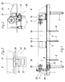
- FIGS. 1, 2 and 3 show a frame 1 on supports 2, two of which can be seen in FIG are.
- Two tailstocks 3, 4 serve in a known manner to clamp the cylindrical screen 5 and to drive it by means of a motor 33 and a toothed belt 34 on the spindle 35 in the tailstock 3.
- this tailstock 4 is axially displaceable in order to be able to insert the screen unhindered from above or from the front.
- Three vertically adjustable supports 6, 7, 8 are used as insertion aids, each of which has a support plate 9 provided with a circular segment-shaped recess with the radius of the sieve 5.
- the coater 20 can be seen in FIGS. 2 and 3 in the present case it consists of a spray head 21 which can have up to 96 nozzles which are arranged in a line at an acute angle to the base of the coater.
- Coating with a spray head 21 with, for example, 96 nozzles is carried out in strips approximately 8 mm wide.
- a drive with a stepping gear can thus be advanced by 8 mm after each single rotation of the screen.
- the starting point for one revolution is determined by a position transmitter 32.
- a light emitter 25 can also be mounted on the coater 20, so that in principle the areas not covered by the wax can be exposed in the same operation.
- the coater is fed by means of a spindle 30 and by means of a ball screw nut 31 and thus in a very uniform form.
- the angle transmitter 32 necessary for the control is used to adjust the setting of the coater 40 with respect to the origin of the pattern in a manner that is inherently arbitrary. This adjustment can advantageously be done with a sine function around the origin. This moves the respective beginning forwards or backwards for one revolution of the sieve and there is no discernible interruption in the pattern.
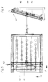
- the coater 40 is moved over the flat screen. Only here the coater 40 is moved in two orthogonal directions. Support heads 43, against which the frame 41 rests in two orthogonal directions and thus have a precisely fixable position, serve for the correct mounting of the flat screen 42 clamped in a frame 41. The screen 42 rests on further support heads 43 in several places and can thus withstand the slight pressure of the coater 40.
- a motor 44 is used, which gradually moves a carriage 47 with the coater 40 via a drive belt 46 tensioned with tensioning elements 45.
- the coater 40 then becomes uniform in the X direction, with known drive means, moved back and forth.
Landscapes
- Physics & Mathematics (AREA)
- General Physics & Mathematics (AREA)
- Engineering & Computer Science (AREA)
- Manufacturing & Machinery (AREA)
- Manufacture Or Reproduction Of Printing Formes (AREA)
- Printing Plates And Materials Therefor (AREA)
- Printing Methods (AREA)
- Manufacturing Of Printed Wiring (AREA)
- Moulding By Coating Moulds (AREA)
- Moulds For Moulding Plastics Or The Like (AREA)
Abstract
Description
- Die vorliegende Erfindung betrifft ein Verfahren zur Herstellung einer Druckschablone mit einem feinmaschigen Sieb, das mit einer unbelichteten Photoemulsionsschicht versehen ist und auf dem diejenigen Stellen, die nicht zu belichten sind, musterbedingt mit einer lichtundurchlässigen Schicht abgedeckt sind, welche Schicht nach der Belichtung entfernt wird.
- Solcherart beschichtete Druckschablonen sind bekannt, wie die EP-A-0 492 351, die EP-A-0 558 098 oder die EP-A- 0 590 164 zeigen. Einzeln betrachtet wird bei der EP-A-0 492 351 ein Pulver, wie z.B. Talkpulver auf das Sieb gegeben, damit die danach aufgespritzte Tinte nicht verfliesst, sondern genaue Konturen bildet. Nachteilig an dieser Anordnung ist die Verwendung des Pulvers, das immer einen Nebel am Arbeitsplatz bildet und damit die Umgebung beeinträchtigt.
- In der EP-A-0 558 098 wird die Ausbildung der Reitstöcke beschrieben, die mit Absätzen versehen sind, um rohrförmige Siebe mit unterschiedlichen Durchmessern zentrieren zu können. Die Herstellung solcher Reitstöcke ist relativ aufwendig und daher teuer, da im Vergleich mit einfachen bekannten Reitstöcken nur diese auszuwechseln wären tritt die Verteuerung erkennbar in den Vordergrund.
- Schliesslich zeigt die EP-A-0 590 164 ein Verfahren, bei dem die Abdeckschicht aus einer zähviskosen Schicht gebildet wird. Als Material für diese zähviskose Schicht wird eine Emulsion eines Kunstharzlackes vorgeschlagen. Ein solches Material hat jedoch eine grosse Haftungskraft auf dem Sieb, ein Auswaschen nach dem Belichten ist nicht vorgesehen, denn die Abdeckflüssigkeit soll resistent gegen Abrasion und gegen chemische Einflüsse der Druckchemikalien sein.
- Dementsprechend ist es eine Aufgabe der Erfindung ein Verfahren anzugeben, nach welchem eine leicht entfernbare Deckschicht mustergenau auf ein Sieb aufbringbar ist, und das Sieb als Rohr oder als ebene Fläche beschichtbar ist.
- Erfindungsgemäss wird dies nach den Merkmalen im Anspruch 1 und in den Ansprüchen 5 und 6 erreicht. Das Verfahren ist dabei dadurch gekennzeichnet, dass als Material für die lichtundurchlässige Schicht Wachs verwendet wird. und die Vorrichtung zur Durchführung des Verfahrens bei einer rohrförmigen Anordnung ist gekennzeichnet durch eine Anzahl Stützen mit je einer kreissegmentförmigen Ausnehmung zur Ausrichtung eines rohrförmigen Siebes auf die Reitstöcke einer Anordnung zum rotieren des Siebes um seine Längsachse.
- Ferner ist die Vorrichtung zur Durchführung des Verfahrens für ein flach angeordnetes Sieb dadurch gekennzeichnet, dass bei Verwendung eines flachen Siebes das Sieb auf einer Anzahl zeilen und spaltenförmig angeordneten Stützen ruht, die auch die Ausrichtung des Rahmens des Siebes in den zwei Hauptrichtungen bewirken.
- Nachfolgend werden Ausführungsbeispiele der Erfindung an Hand der Zeichnungen erläutert. Es zeigen:
- Fig.1
- einen Aufriss einer Vorrichtung zum Beschichten eines zylindrischen Siebes mit Mitteln zum Aufspannen desselben,
- Fig.2
- einen Seitenriss von rechts in Fig. 1 gesehen,
- Fig.3
- eine Draufsicht auf den Schlitten mit der Spritzdüsenanordnung und den zugehörigen Steuerungsmitteln,
- Fig.4
- einen Seitenriss einer Vorrichtung zum Beschichten eines ebenen Siebes, und
- Fig.5
- eine Vorderansicht der Halterung des Einspannrahmens des Siebes.
- Die Anordnung zur Beschichtung eines zylindrischen Siebes gemäss Fig. 1, 2 und 3 zeigt ein Gestell 1 auf stützen 2, von denen zwei in Fig.1 ersichtlich sind. Zwei Reitstöcke 3,4 dienen in bekannter Weise zum Einspannen des zylinderförmigen Siebes 5 und zu dessen Antrieb mittels eines Motors 33 und einem Zahnriemen 34 auf die Spindel 35 im Reitstock 3. Wie durch die mit unterbrochenen Linien dargestellte Lage des Reitstockes 4 als Reitstock 4' gezeigt ist, ist dieser Reitstock 4 axial verschieblich angeordnet, um das Sieb ungehindert von oben oder von vorn einlegen zu können. Als Einlegehilfe dienen beispielsweise drei vertikal einstellbare Stützen 6,7,8 die je ein mit einer kreissegmentförmigen Ausnehmung mit dem Radius des Siebes 5 versehene Auflageplatte 9 aufweisen. Diese Stützen 6,7,8 werden mechanisch oder pneumatisch hochgefahren, so dass die Auflageplatten in die Stellung 9a kommen und damit ein Bett für das Sieb 5 bilden. Nach dem Einfahren des Reitstockes 4 in die Haltelage wird das Sieb 5 zentriert und mittels eines Gebläses 10 wird Luft in das Sieb geblasen, so dass dieses die korrekte kreiszylindrische Form einnimmt.
- Der Beschichter 20 ist in Fig.2 und 3 ersichtlich im vorliegenden Fall besteht er aus einem Sprühkopf 21 der bis zu 96 Düsen aufweisen kann, die unter einem spitzen Winkel zur Basis des Beschichters linienartig angeordnet sind. Auf dem Beschichter 20 befinden sich ausserdem die Steuerung 22 mit einem Datengeber, durch den die einzelnen Düsen des Sprühkopfes 21 gesteuert werden, d.h. geschlossen oder geöffnet werden. Auf dem Beschichter 20 befindet sich selbstverständlich auch das Reservoir 24 für die Beschichtungsflüssigkeit, im vorliegenden Falle mit Leim vermischtes Wachs, das somit erwärmt und mittels wärmegeschützter Leitung 23 dem Sprühkopf 21 zugeleitet wird.
- Die Beschichtung mit einem Sprühkopf 21 mit beispielsweise 96 Düsen erfolgt in Bändern mit etwa 8 mm Breite. Ein Antrieb mit einem Schrittgetriebe kann somit jeweils nach einer einzigen Umdrehung des Siebes um 8 mm vorgeschoben werden. Der Anfangspunkt für eine Umdrehung wird durch einen Stellungsgeber 32 bestimmt.
- Ein Lichtstrahler 25 kann ebenfalls auf den Beschichter 20 montiert sein, so dass grundsätzlich die Belichtung der nicht durch das Wachs abgedeckte Stellen im gleichen Arbeitsgang erfolgen kann.
- Der Vorschub des Beschichters erfolgt mittels einer Spindel 30, und mittels einer Kugelschraubenmutter 31 und damit in sehr gleichmässiger Form.
- Es ist leicht einzusehen, dass eine Beschichtung die immer an derselben Stelle des Umfanges des zylindrischen Siebes ihren Ursprung hat eine Linie im Muster erzeugen kann. Um das zu beheben wird der für die Steuerung notwendige Winkelgeber 32 benützt, um die Einstellung des Beschichters 40 bezüglich des Ursprungs des Musters in an sich beliebiger Weise zu verstellen. Vorteilhafterweise kann diese Verstellung mit einer Sinusfunktion um den Ursprung herum geschehen. Damit wird der jeweilige Anfang für eine Umdrehung des Siebes vor- oder zurückverschoben und es kann sich keine erkennbare unterbrechung im Muster ergeben.
- In ähnlicher Weise wird auch der Beschichter 40 über das flache Sieb bewegt. Nur dass hier der Beschichter 40 in zwei orthogonalen Richtungen bewegt wird. Zur korrekten Halterung des ebenen, in einen Rahmen 41 eingespannten Siebes 42 dienen Stützköpfe 43, an die der Rahmen 41 in zwei orthogonalen Richtungen anliegt und so eine genau fixierbare Lage hat. Das Sieb 42 liegt an mehreren Stellen auf weiteren Stützköpfen 43 auf und kann dadurch dem leichten Druck des Beschichters 40 widerstehen. Für den Antrieb in Y-Richtung (siehe Fig.5) dient ein Motor 44, der über ein mit Spannelementen 45 gespanntes Antriebsband 46 einen Schlitten 47 mit dem Beschichter 40 schrittweise verschiebt. In X-Richtung wird dann der Beschichter 40 gleichmässig, mit an sich bekannten Antriebsmitteln, hin und herbewegt. Es ist dabei nicht wichtig, ob der Beschichter in beiden Verschieberichtungen das Sieb besprüht oder nur in einer Richtung, wenn man bedenkt, dass die jeweilige Beschichtungsbreite von 8 mm mit den 96 Düsen vor der nachfolgenden Beschichtung vorgeschoben werden muss, könnte ebensogut mit einem raschen Rücklauf wieder an derselben Randstelle des Rahmens beschichtet werden.
Claims (7)
- Verfahren zur Herstellung einer Druckschablone mit einem feinmaschigen Sieb, das mit einer unbelichteten Photoemulsionsschicht versehen ist und auf dem diejenigen Stellen, die nicht zu belichten sind, musterbedingt mit einer lichtundurchlässigen Schicht abgedeckt sind, welche Schicht nach der Belichtung entfernt wird, dadurch gekennzeichnet, dass als Material für die lichtundurchlässige Schicht Wachs verwendet wird.
- Verfahren nach Anspruch 1, dadurch gekennzeichnet, dass bei einem rohrförmigen Sieb der Musteranfang gesetzmässig variiert wird, um eine markante Trennlinie zu vermeiden.
- Verfahren nach Anspruch 2, dadurch gekennzeichnet, dass die gesetzmässige Variation einer Sinuslinie folgt.
- Verfahren nach einem der Ansprüche 1 bis 3, dadurch gekennzeichnet, dass das beschichtete Sieb der Beschichtung nachfolgend belichtet wird.
- Vorrichtung zur Durchführung des Verfahrens nach Anspruch 1, gekennzeichnet durch eine Anzahl Stützen mit je einer kreissegmentförmigen Ausnehmung zur Ausrichtung eines rohrförmigen Siebes auf die Reitstöcke einer Anordnung zum rotieren des Siebes um seine Längsachse.
- Vorrichtung zur Durchführung des Verfahrens nach Anspruch 1, dadurch gekennzeichnet, dass bei Verwendung eines flachen Siebes das Sieb auf einer Anzahl zeilen und spaltenförmig angeordneten Stützen ruht, die auch die Ausrichtung des Rahmens des Siebes in den zwei Hauptrichtungen bewirken.
- Vorrichtung nach Anspruch 5, dadurch gekennzeichnet, dass wenigstens der eine Reitstock mit einer Zuführung von Pressluft in den zylindrischen Hohlraum des rohrförmigen Siebes ausgebildet ist.
Applications Claiming Priority (2)
| Application Number | Priority Date | Filing Date | Title |
|---|---|---|---|
| CH00213/95A CH690030A5 (de) | 1995-01-26 | 1995-01-26 | Verfahren und Vorrichtung zur Herstellung einer Druckschablone. |
| CH213/95 | 1995-01-26 |
Publications (3)
| Publication Number | Publication Date |
|---|---|
| EP0733951A2 true EP0733951A2 (de) | 1996-09-25 |
| EP0733951A3 EP0733951A3 (de) | 1996-12-18 |
| EP0733951B1 EP0733951B1 (de) | 1998-09-02 |
Family
ID=4181849
Family Applications (1)
| Application Number | Title | Priority Date | Filing Date |
|---|---|---|---|
| EP96101052A Expired - Lifetime EP0733951B1 (de) | 1995-01-26 | 1996-01-25 | Verfahren und Vorrichtung zur Herstellung einer Druckschablone |
Country Status (13)
| Country | Link |
|---|---|
| EP (1) | EP0733951B1 (de) |
| JP (1) | JP3022298B2 (de) |
| KR (1) | KR960029098A (de) |
| CN (1) | CN1074990C (de) |
| AT (1) | ATE170639T1 (de) |
| BR (1) | BR9600213A (de) |
| CH (1) | CH690030A5 (de) |
| DE (1) | DE59600495D1 (de) |
| DK (1) | DK0733951T3 (de) |
| ES (1) | ES2123304T3 (de) |
| HK (1) | HK1000635A1 (de) |
| IL (1) | IL116630A (de) |
| RU (1) | RU2157763C2 (de) |
Cited By (3)
| Publication number | Priority date | Publication date | Assignee | Title |
|---|---|---|---|---|
| DE19725488A1 (de) * | 1997-06-17 | 1999-01-21 | Kissel & Wolf Gmbh | Verfahren zur Herstellung einer Siebdruckform und Vorrichtung zur Durchführung des Verfahrens |
| EP1154326A1 (de) * | 2000-05-12 | 2001-11-14 | Schablonentechnik Kufstein Aktiengesellschaft | Verfahren und Vorrichtung zur Herstellung von Druckplatten |
| WO2002094580A1 (de) * | 2001-05-22 | 2002-11-28 | Berndorf Band Gesmbh | Verfahren zum strukturieren von endlosen bändern für pressen |
Families Citing this family (8)
| Publication number | Priority date | Publication date | Assignee | Title |
|---|---|---|---|---|
| AU3834800A (en) * | 2000-03-24 | 2001-10-03 | F. Lli Robustelli Srl | Method for centered screen printing and apparatus |
| US20150336301A1 (en) | 2012-05-02 | 2015-11-26 | Rolith, Inc. | Cylindrical polymer mask and method of fabrication |
| JP6278954B2 (ja) * | 2012-05-02 | 2018-02-14 | メタマテリアル テクノロジーズ ユーエスエー インコーポレイテッド | 円柱状ポリマーマスクおよび製造方法 |
| US9481112B2 (en) | 2013-01-31 | 2016-11-01 | Metamaterial Technologies Usa, Inc. | Cylindrical master mold assembly for casting cylindrical masks |
| US9782917B2 (en) | 2013-01-31 | 2017-10-10 | Metamaterial Technologies Usa, Inc. | Cylindrical master mold and method of fabrication |
| US10088914B2 (en) * | 2013-06-13 | 2018-10-02 | Microsoft Technology Licensing, Llc | Modifying input delivery to applications |
| CN104742493A (zh) * | 2013-12-27 | 2015-07-01 | 乐凯华光印刷科技有限公司 | 一种丝网印刷版及其制造方法 |
| CN111391475A (zh) * | 2020-04-18 | 2020-07-10 | 杨林 | 一种印刷丝网印版线形流动曝光装置 |
Family Cites Families (15)
| Publication number | Priority date | Publication date | Assignee | Title |
|---|---|---|---|---|
| SE419199B (sv) * | 1977-05-16 | 1981-07-20 | Svecia Silkscreen Maskiner Ab | Anordning for framstellning av en stencil |
| US4390369A (en) * | 1981-12-17 | 1983-06-28 | Exxon Research And Engineering Co. | Natural wax-containing ink jet inks |
| US5154121A (en) * | 1988-11-09 | 1992-10-13 | Man Roland Druckmaschinen Ag | System and method to apply a printing image on a printing machine cylinder having ink accepting receptors or cells, in accordance with electronically furnished image information |
| AT393979B (de) * | 1989-11-07 | 1992-01-10 | Kufstein Schablonentech Gmbh | Vorrichtung zum bearbeiten von hohlzylindern mittels eines lasers |
| CN1022417C (zh) * | 1990-06-04 | 1993-10-13 | 中国科学院长春应用化学研究所 | 速溶阴离子型聚丙烯酰胺制备 |
| US5156089A (en) * | 1990-12-17 | 1992-10-20 | Gerber Scientific Products, Inc. | Method and apparatus for making a painting screen using an ink jet printer for printing a graphic on the screen emulsion |
| US5192641A (en) * | 1990-12-19 | 1993-03-09 | Hoechst Celanese Corporation | Method of thermal wax transfer as a mask for digital color proofing |
| US5345254A (en) * | 1991-05-16 | 1994-09-06 | Xerox Corporation | Ink jet printing process |
| DE4132668C2 (de) * | 1991-10-01 | 1993-09-30 | Kammann Maschf Werner | Vorrichtung und Verfahren zum Dekorieren eines kegelförmigen Körpers |
| US5156098A (en) * | 1992-01-06 | 1992-10-20 | William W. Bailey | Two chamber burner apparatus for destroying waste liquids |
| US5247315A (en) * | 1992-02-06 | 1993-09-21 | Gerber Scientific Products, Inc. | Method of printing a graphic having uniform ink density on an emulsion coated printing screen |
| DE59202410D1 (de) * | 1992-03-27 | 1995-07-06 | Kufstein Schablonentech Gmbh | Vorrichtung zum Bearbeiten dünnwandiger Hohlzylinder mittels eines Laserstrahls. |
| DE59209985D1 (de) * | 1992-09-22 | 2003-09-11 | Schablonentechnik Kufstein Ag | Vorrichtung zum Aufbringen einer Abdeckflüssigkeit auf einen Zylinder |
| EP0622190B1 (de) * | 1993-04-28 | 1996-03-06 | Schablonentechnik Kufstein Aktiengesellschaft | Vorrichtung zum formstabilen Aufspannen eines dünnwandigen Hohlzylinders |
| JP6151549B2 (ja) | 2013-04-22 | 2017-06-21 | Hoya株式会社 | 内視鏡用光源装置 |
-
1995
- 1995-01-26 CH CH00213/95A patent/CH690030A5/de not_active IP Right Cessation
- 1995-12-31 IL IL11663095A patent/IL116630A/en not_active IP Right Cessation
-
1996
- 1996-01-16 KR KR1019960000691A patent/KR960029098A/ko not_active Withdrawn
- 1996-01-25 DK DK96101052T patent/DK0733951T3/da not_active Application Discontinuation
- 1996-01-25 ES ES96101052T patent/ES2123304T3/es not_active Expired - Lifetime
- 1996-01-25 AT AT96101052T patent/ATE170639T1/de active
- 1996-01-25 BR BR9600213A patent/BR9600213A/pt not_active IP Right Cessation
- 1996-01-25 DE DE59600495T patent/DE59600495D1/de not_active Expired - Lifetime
- 1996-01-25 EP EP96101052A patent/EP0733951B1/de not_active Expired - Lifetime
- 1996-01-25 JP JP8011061A patent/JP3022298B2/ja not_active Expired - Fee Related
- 1996-01-26 CN CN96100876A patent/CN1074990C/zh not_active Expired - Fee Related
- 1996-01-26 RU RU96102671/12A patent/RU2157763C2/ru not_active IP Right Cessation
-
1997
- 1997-11-18 HK HK97102190A patent/HK1000635A1/xx not_active IP Right Cessation
Cited By (7)
| Publication number | Priority date | Publication date | Assignee | Title |
|---|---|---|---|---|
| DE19725488A1 (de) * | 1997-06-17 | 1999-01-21 | Kissel & Wolf Gmbh | Verfahren zur Herstellung einer Siebdruckform und Vorrichtung zur Durchführung des Verfahrens |
| EP0885718A3 (de) * | 1997-06-17 | 1999-03-03 | Kissel & Wolf GmbH | Verfahren zur Herstellung einer Siebdruckform und Vorrichtung zur Durchführung des Verfahrens |
| EP1154326A1 (de) * | 2000-05-12 | 2001-11-14 | Schablonentechnik Kufstein Aktiengesellschaft | Verfahren und Vorrichtung zur Herstellung von Druckplatten |
| WO2002094580A1 (de) * | 2001-05-22 | 2002-11-28 | Berndorf Band Gesmbh | Verfahren zum strukturieren von endlosen bändern für pressen |
| AT500267A1 (de) * | 2001-05-22 | 2005-11-15 | Berndorf Band Ges M B H | Verfahren zum strukturieren von endlosen bändern für pressen |
| AT500267B1 (de) * | 2001-05-22 | 2006-08-15 | Berndorf Band Ges M B H | Verfahren zum strukturieren von endlosen bändern für pressen |
| US7371430B2 (en) | 2001-05-22 | 2008-05-13 | Berndorf Band Gmbh & Co. | Method for structuring endless belts for presses |
Also Published As
| Publication number | Publication date |
|---|---|
| ATE170639T1 (de) | 1998-09-15 |
| DE59600495D1 (de) | 1998-10-08 |
| ES2123304T3 (es) | 1999-01-01 |
| BR9600213A (pt) | 1998-01-06 |
| EP0733951B1 (de) | 1998-09-02 |
| RU2157763C2 (ru) | 2000-10-20 |
| IL116630A (en) | 1998-10-30 |
| CN1154910A (zh) | 1997-07-23 |
| EP0733951A3 (de) | 1996-12-18 |
| KR960029098A (ko) | 1996-08-17 |
| CH690030A5 (de) | 2000-03-31 |
| HK1000635A1 (en) | 2002-03-15 |
| IL116630A0 (en) | 1996-03-31 |
| JPH08238863A (ja) | 1996-09-17 |
| DK0733951T3 (da) | 1999-06-07 |
| JP3022298B2 (ja) | 2000-03-15 |
| CN1074990C (zh) | 2001-11-21 |
Similar Documents
| Publication | Publication Date | Title |
|---|---|---|
| EP0897796B1 (de) | Verfahren zur Herstellung einer Siebdruckschablone und hierfür geeignete Vorrichtung | |
| DE102006022722B4 (de) | Verfahren und Vorrichtung zur Oberflächenstrukturierung eines Pressbleches oder eines Endlosbandes | |
| EP0733951B1 (de) | Verfahren und Vorrichtung zur Herstellung einer Druckschablone | |
| DE19633407A1 (de) | Vorrichtung und Verfahren zum Auftragen von Fotoresist auf nicht ebene Grundkörperflächen für fotolithografische Verfahren | |
| DD241567A5 (de) | Verfahren und Vorrichtung zur Herstellung einer Siebdruckschablone | |
| EP0558098A2 (de) | Vorrichtung zum Bearbeiten von Hohlzylindern mittels eines Lasers | |
| DE68902168T2 (de) | Vorrichtung und verfahren zum herstellen einer rotationssiebdruckschablone. | |
| EP0714766B1 (de) | Vorrichtung zur Herstellung von Druckschablonen | |
| AT411741B (de) | Verfahren und einrichtung zur herstellung eines stempels | |
| DE102016013317B4 (de) | Verfahren zum Herstellen eines dreidimensionalen Formgegenstands und Vorrichtung zur Durchführung des Verfahrens | |
| EP4008523B1 (de) | Verfahren und vorrichtung zum schichtweisen aufbau eines bauteils aus photopolymerisierbarem material | |
| EP0818711B1 (de) | Vorrichtung zum Aufbringen einer Abdeckflüssigkeit auf einen Zylinder | |
| DE4018113A1 (de) | Vorrichtung zum entfernen von etiketten und folienzuschnitten mittels axial versetzter trennmittelduesen | |
| DE2524824A1 (de) | Giessvorrichtung mit schlitzartiger ausflussoeffnung | |
| EP0043077A1 (de) | Verfahren und Vorrichtung zum Beschichten der Aussenflächen von Glasflaschen | |
| DE69409940T2 (de) | Gravurgerät für zylindrische Gummimatrix | |
| DE102017205741A1 (de) | Beschichtungseinrichtung, Verfahren zum Herstellen eines beschichteten Bauteils und Kraftfahrzeug | |
| DE2359088A1 (de) | Verfahren und vorrichtung zum auftragen einer schicht aus fluessigem material auf die aussenseite einer zylindrischen siebschablone | |
| DE102010047924A1 (de) | Verfahren und Vorrichtung zum Erzeugen einer Oberfläche einer aushärtenden Flüssigkeit | |
| DE102016013319A1 (de) | Vorrichtung und Verfahren zum Aufbringen von fließfähigem Material auf eine um eine Drehachse drehbare Unterlage | |
| EP0802047B1 (de) | Halbtonschablone sowie Verfahren und Vorrichtung zu ihrer Herstellung | |
| DE60006285T2 (de) | Druckhülse mit befestigungsmitteln für druckplatten und verfahren zu ihrer herstellung | |
| EP0850134B1 (de) | Verfahren und vorrichtungen zum beschichten eines trägerteils | |
| EP0785474A1 (de) | Verfahren und Vorrichtung zur Herstellung einer Flexodruckschablone | |
| DE2549758A1 (de) | Farbspritzwerk |
Legal Events
| Date | Code | Title | Description |
|---|---|---|---|
| PUAI | Public reference made under article 153(3) epc to a published international application that has entered the european phase |
Free format text: ORIGINAL CODE: 0009012 |
|
| AK | Designated contracting states |
Kind code of ref document: A2 Designated state(s): AT BE CH DE DK ES FR GB GR IE IT LI LU MC NL PT SE |
|
| PUAL | Search report despatched |
Free format text: ORIGINAL CODE: 0009013 |
|
| AK | Designated contracting states |
Kind code of ref document: A3 Designated state(s): AT BE CH DE DK ES FR GB GR IE IT LI LU MC NL PT SE |
|
| 17P | Request for examination filed |
Effective date: 19970204 |
|
| 17Q | First examination report despatched |
Effective date: 19970506 |
|
| GRAG | Despatch of communication of intention to grant |
Free format text: ORIGINAL CODE: EPIDOS AGRA |
|
| GRAG | Despatch of communication of intention to grant |
Free format text: ORIGINAL CODE: EPIDOS AGRA |
|
| GRAG | Despatch of communication of intention to grant |
Free format text: ORIGINAL CODE: EPIDOS AGRA |
|
| GRAH | Despatch of communication of intention to grant a patent |
Free format text: ORIGINAL CODE: EPIDOS IGRA |
|
| GRAH | Despatch of communication of intention to grant a patent |
Free format text: ORIGINAL CODE: EPIDOS IGRA |
|
| GRAA | (expected) grant |
Free format text: ORIGINAL CODE: 0009210 |
|
| AK | Designated contracting states |
Kind code of ref document: B1 Designated state(s): AT BE CH DE DK ES FR GB GR IE IT LI LU MC NL PT SE |
|
| REF | Corresponds to: |
Ref document number: 170639 Country of ref document: AT Date of ref document: 19980915 Kind code of ref document: T |
|
| REG | Reference to a national code |
Ref country code: CH Ref legal event code: EP |
|
| REF | Corresponds to: |
Ref document number: 59600495 Country of ref document: DE Date of ref document: 19981008 |
|
| REG | Reference to a national code |
Ref country code: CH Ref legal event code: NV Representative=s name: R. A. EGLI & CO. PATENTANWAELTE |
|
| GBT | Gb: translation of ep patent filed (gb section 77(6)(a)/1977) |
Effective date: 19981105 |
|
| REG | Reference to a national code |
Ref country code: IE Ref legal event code: FG4D Free format text: GERMAN |
|
| ET | Fr: translation filed | ||
| REG | Reference to a national code |
Ref country code: ES Ref legal event code: FG2A Ref document number: 2123304 Country of ref document: ES Kind code of ref document: T3 |
|
| REG | Reference to a national code |
Ref country code: PT Ref legal event code: SC4A Free format text: AVAILABILITY OF NATIONAL TRANSLATION Effective date: 19981202 |
|
| REG | Reference to a national code |
Ref country code: CH Ref legal event code: PUE Owner name: LUESCHER, HANS;LUESCHER, URSULA TRANSFER- FINGRAF |
|
| REG | Reference to a national code |
Ref country code: GB Ref legal event code: 732E |
|
| REG | Reference to a national code |
Ref country code: DK Ref legal event code: T3 |
|
| REG | Reference to a national code |
Ref country code: FR Ref legal event code: TP |
|
| REG | Reference to a national code |
Ref country code: PT Ref legal event code: PC4A Free format text: FINGRAF AG CH Effective date: 19990323 |
|
| NLS | Nl: assignments of ep-patents |
Owner name: FINGRAF AG |
|
| PLBQ | Unpublished change to opponent data |
Free format text: ORIGINAL CODE: EPIDOS OPPO |
|
| PLBI | Opposition filed |
Free format text: ORIGINAL CODE: 0009260 |
|
| PLBF | Reply of patent proprietor to notice(s) of opposition |
Free format text: ORIGINAL CODE: EPIDOS OBSO |
|
| 26 | Opposition filed |
Opponent name: KISSEL & WOLF GMBH Effective date: 19990601 |
|
| REG | Reference to a national code |
Ref country code: ES Ref legal event code: PC2A |
|
| PLBI | Opposition filed |
Free format text: ORIGINAL CODE: 0009260 |
|
| PLAV | Examination of admissibility of opposition |
Free format text: ORIGINAL CODE: EPIDOS OPEX |
|
| 26 | Opposition filed |
Opponent name: F.LLI ROBUSTELLI S.R.L. Effective date: 19990918 Opponent name: KISSEL & WOLF GMBH Effective date: 19990601 |
|
| NLR1 | Nl: opposition has been filed with the epo |
Opponent name: F.LLI ROBUSTELLI S.R.L. Opponent name: KISSEL & WOLF GMBH |
|
| PLBF | Reply of patent proprietor to notice(s) of opposition |
Free format text: ORIGINAL CODE: EPIDOS OBSO |
|
| PLBF | Reply of patent proprietor to notice(s) of opposition |
Free format text: ORIGINAL CODE: EPIDOS OBSO |
|
| REG | Reference to a national code |
Ref country code: GB Ref legal event code: IF02 |
|
| PGFP | Annual fee paid to national office [announced via postgrant information from national office to epo] |
Ref country code: MC Payment date: 20050120 Year of fee payment: 10 |
|
| PGFP | Annual fee paid to national office [announced via postgrant information from national office to epo] |
Ref country code: PT Payment date: 20050121 Year of fee payment: 10 |
|
| PGFP | Annual fee paid to national office [announced via postgrant information from national office to epo] |
Ref country code: LU Payment date: 20050124 Year of fee payment: 10 |
|
| PGFP | Annual fee paid to national office [announced via postgrant information from national office to epo] |
Ref country code: GR Payment date: 20050126 Year of fee payment: 10 |
|
| PG25 | Lapsed in a contracting state [announced via postgrant information from national office to epo] |
Ref country code: MC Free format text: LAPSE BECAUSE OF NON-PAYMENT OF DUE FEES Effective date: 20060131 Ref country code: LU Free format text: LAPSE BECAUSE OF NON-PAYMENT OF DUE FEES Effective date: 20060131 |
|
| PG25 | Lapsed in a contracting state [announced via postgrant information from national office to epo] |
Ref country code: PT Free format text: LAPSE BECAUSE OF NON-PAYMENT OF DUE FEES Effective date: 20060725 |
|
| REG | Reference to a national code |
Ref country code: PT Ref legal event code: MM4A Effective date: 20060725 |
|
| PLBP | Opposition withdrawn |
Free format text: ORIGINAL CODE: 0009264 |
|
| PLAY | Examination report in opposition despatched + time limit |
Free format text: ORIGINAL CODE: EPIDOSNORE2 |
|
| PLBC | Reply to examination report in opposition received |
Free format text: ORIGINAL CODE: EPIDOSNORE3 |
|
| RAP2 | Party data changed (patent owner data changed or rights of a patent transferred) |
Owner name: FINGRAF AG |
|
| PLCK | Communication despatched that opposition was rejected |
Free format text: ORIGINAL CODE: EPIDOSNREJ1 |
|
| NLT2 | Nl: modifications (of names), taken from the european patent patent bulletin |
Owner name: FINGRAF AG Effective date: 20071031 |
|
| PLBN | Opposition rejected |
Free format text: ORIGINAL CODE: 0009273 |
|
| STAA | Information on the status of an ep patent application or granted ep patent |
Free format text: STATUS: OPPOSITION REJECTED |
|
| 27O | Opposition rejected |
Effective date: 20070710 |
|
| NLR2 | Nl: decision of opposition |
Effective date: 20070710 |
|
| PLAB | Opposition data, opponent's data or that of the opponent's representative modified |
Free format text: ORIGINAL CODE: 0009299OPPO |
|
| PG25 | Lapsed in a contracting state [announced via postgrant information from national office to epo] |
Ref country code: GR Free format text: LAPSE BECAUSE OF NON-PAYMENT OF DUE FEES Effective date: 20060802 |
|
| PGFP | Annual fee paid to national office [announced via postgrant information from national office to epo] |
Ref country code: IE Payment date: 20090123 Year of fee payment: 14 Ref country code: ES Payment date: 20090122 Year of fee payment: 14 Ref country code: DK Payment date: 20090113 Year of fee payment: 14 |
|
| PGFP | Annual fee paid to national office [announced via postgrant information from national office to epo] |
Ref country code: NL Payment date: 20090114 Year of fee payment: 14 |
|
| PGFP | Annual fee paid to national office [announced via postgrant information from national office to epo] |
Ref country code: GB Payment date: 20090122 Year of fee payment: 14 |
|
| PGFP | Annual fee paid to national office [announced via postgrant information from national office to epo] |
Ref country code: BE Payment date: 20090219 Year of fee payment: 14 |
|
| PGFP | Annual fee paid to national office [announced via postgrant information from national office to epo] |
Ref country code: SE Payment date: 20090114 Year of fee payment: 14 |
|
| PGFP | Annual fee paid to national office [announced via postgrant information from national office to epo] |
Ref country code: FR Payment date: 20090115 Year of fee payment: 14 |
|
| BERE | Be: lapsed |
Owner name: *FINGRAF A.G. Effective date: 20100131 |
|
| REG | Reference to a national code |
Ref country code: NL Ref legal event code: V1 Effective date: 20100801 |
|
| REG | Reference to a national code |
Ref country code: DK Ref legal event code: EBP |
|
| GBPC | Gb: european patent ceased through non-payment of renewal fee |
Effective date: 20100125 |
|
| EUG | Se: european patent has lapsed | ||
| REG | Reference to a national code |
Ref country code: FR Ref legal event code: ST Effective date: 20100930 |
|
| REG | Reference to a national code |
Ref country code: IE Ref legal event code: MM4A |
|
| PG25 | Lapsed in a contracting state [announced via postgrant information from national office to epo] |
Ref country code: NL Free format text: LAPSE BECAUSE OF NON-PAYMENT OF DUE FEES Effective date: 20100801 Ref country code: FR Free format text: LAPSE BECAUSE OF NON-PAYMENT OF DUE FEES Effective date: 20100201 |
|
| PG25 | Lapsed in a contracting state [announced via postgrant information from national office to epo] |
Ref country code: GB Free format text: LAPSE BECAUSE OF NON-PAYMENT OF DUE FEES Effective date: 20100125 |
|
| PG25 | Lapsed in a contracting state [announced via postgrant information from national office to epo] |
Ref country code: IE Free format text: LAPSE BECAUSE OF NON-PAYMENT OF DUE FEES Effective date: 20100125 Ref country code: DK Free format text: LAPSE BECAUSE OF NON-PAYMENT OF DUE FEES Effective date: 20100131 |
|
| PG25 | Lapsed in a contracting state [announced via postgrant information from national office to epo] |
Ref country code: BE Free format text: LAPSE BECAUSE OF NON-PAYMENT OF DUE FEES Effective date: 20100131 |
|
| REG | Reference to a national code |
Ref country code: ES Ref legal event code: FD2A Effective date: 20111118 |
|
| PG25 | Lapsed in a contracting state [announced via postgrant information from national office to epo] |
Ref country code: ES Free format text: LAPSE BECAUSE OF NON-PAYMENT OF DUE FEES Effective date: 20100126 |
|
| PG25 | Lapsed in a contracting state [announced via postgrant information from national office to epo] |
Ref country code: SE Free format text: LAPSE BECAUSE OF NON-PAYMENT OF DUE FEES Effective date: 20100126 |
|
| PGFP | Annual fee paid to national office [announced via postgrant information from national office to epo] |
Ref country code: DE Payment date: 20140122 Year of fee payment: 19 |
|
| PGFP | Annual fee paid to national office [announced via postgrant information from national office to epo] |
Ref country code: AT Payment date: 20140113 Year of fee payment: 19 Ref country code: IT Payment date: 20140131 Year of fee payment: 19 |
|
| PGFP | Annual fee paid to national office [announced via postgrant information from national office to epo] |
Ref country code: CH Payment date: 20140423 Year of fee payment: 19 |
|
| REG | Reference to a national code |
Ref country code: DE Ref legal event code: R119 Ref document number: 59600495 Country of ref document: DE |
|
| REG | Reference to a national code |
Ref country code: CH Ref legal event code: PL |
|
| REG | Reference to a national code |
Ref country code: AT Ref legal event code: MM01 Ref document number: 170639 Country of ref document: AT Kind code of ref document: T Effective date: 20150125 |
|
| PG25 | Lapsed in a contracting state [announced via postgrant information from national office to epo] |
Ref country code: DE Free format text: LAPSE BECAUSE OF NON-PAYMENT OF DUE FEES Effective date: 20150801 Ref country code: CH Free format text: LAPSE BECAUSE OF NON-PAYMENT OF DUE FEES Effective date: 20150131 Ref country code: LI Free format text: LAPSE BECAUSE OF NON-PAYMENT OF DUE FEES Effective date: 20150131 |
|
| PG25 | Lapsed in a contracting state [announced via postgrant information from national office to epo] |
Ref country code: AT Free format text: LAPSE BECAUSE OF NON-PAYMENT OF DUE FEES Effective date: 20150125 |
|
| PG25 | Lapsed in a contracting state [announced via postgrant information from national office to epo] |
Ref country code: IT Free format text: LAPSE BECAUSE OF NON-PAYMENT OF DUE FEES Effective date: 20150125 |