EP0733956B1 - Appareil de formation d'images - Google Patents
Appareil de formation d'images Download PDFInfo
- Publication number
- EP0733956B1 EP0733956B1 EP96301941A EP96301941A EP0733956B1 EP 0733956 B1 EP0733956 B1 EP 0733956B1 EP 96301941 A EP96301941 A EP 96301941A EP 96301941 A EP96301941 A EP 96301941A EP 0733956 B1 EP0733956 B1 EP 0733956B1
- Authority
- EP
- European Patent Office
- Prior art keywords
- image
- transfer material
- sheet
- electricity removing
- potential
- Prior art date
- Legal status (The legal status is an assumption and is not a legal conclusion. Google has not performed a legal analysis and makes no representation as to the accuracy of the status listed.)
- Expired - Lifetime
Links
- 230000005611 electricity Effects 0.000 claims description 194
- 239000000463 material Substances 0.000 claims description 86
- 230000001419 dependent effect Effects 0.000 claims 1
- 238000000926 separation method Methods 0.000 description 23
- 239000011800 void material Substances 0.000 description 22
- 230000015572 biosynthetic process Effects 0.000 description 18
- 230000000630 rising effect Effects 0.000 description 13
- 230000002441 reversible effect Effects 0.000 description 12
- 238000010586 diagram Methods 0.000 description 10
- 230000003247 decreasing effect Effects 0.000 description 9
- 238000004140 cleaning Methods 0.000 description 8
- 238000001514 detection method Methods 0.000 description 8
- 238000000034 method Methods 0.000 description 8
- 230000008569 process Effects 0.000 description 7
- 230000009471 action Effects 0.000 description 6
- 239000003990 capacitor Substances 0.000 description 6
- 238000010521 absorption reaction Methods 0.000 description 5
- 229910052751 metal Inorganic materials 0.000 description 5
- 239000002184 metal Substances 0.000 description 5
- 230000008859 change Effects 0.000 description 4
- 230000003111 delayed effect Effects 0.000 description 4
- 230000000694 effects Effects 0.000 description 4
- 238000009413 insulation Methods 0.000 description 4
- 239000004411 aluminium Substances 0.000 description 3
- 229910052782 aluminium Inorganic materials 0.000 description 3
- XAGFODPZIPBFFR-UHFFFAOYSA-N aluminium Chemical compound [Al] XAGFODPZIPBFFR-UHFFFAOYSA-N 0.000 description 3
- 230000009467 reduction Effects 0.000 description 3
- 239000011347 resin Substances 0.000 description 3
- 229920005989 resin Polymers 0.000 description 3
- 239000002131 composite material Substances 0.000 description 2
- 238000011109 contamination Methods 0.000 description 2
- 230000000994 depressogenic effect Effects 0.000 description 2
- 229910052736 halogen Inorganic materials 0.000 description 2
- 150000002367 halogens Chemical class 0.000 description 2
- 238000005259 measurement Methods 0.000 description 2
- 238000011144 upstream manufacturing Methods 0.000 description 2
- 241001417534 Lutjanidae Species 0.000 description 1
- CBENFWSGALASAD-UHFFFAOYSA-N Ozone Chemical compound [O-][O+]=O CBENFWSGALASAD-UHFFFAOYSA-N 0.000 description 1
- 238000005452 bending Methods 0.000 description 1
- 239000011248 coating agent Substances 0.000 description 1
- 238000000576 coating method Methods 0.000 description 1
- 230000006866 deterioration Effects 0.000 description 1
- 238000007599 discharging Methods 0.000 description 1
- 230000007613 environmental effect Effects 0.000 description 1
- 238000007667 floating Methods 0.000 description 1
- 230000020169 heat generation Effects 0.000 description 1
- 238000010438 heat treatment Methods 0.000 description 1
- 230000010355 oscillation Effects 0.000 description 1
- 108091008695 photoreceptors Proteins 0.000 description 1
- 238000007639 printing Methods 0.000 description 1
- 230000001737 promoting effect Effects 0.000 description 1
- 230000004044 response Effects 0.000 description 1
- 238000007790 scraping Methods 0.000 description 1
- 230000001360 synchronised effect Effects 0.000 description 1
- 239000002699 waste material Substances 0.000 description 1
- 239000002023 wood Substances 0.000 description 1
Images






Classifications
-
- G—PHYSICS
- G03—PHOTOGRAPHY; CINEMATOGRAPHY; ANALOGOUS TECHNIQUES USING WAVES OTHER THAN OPTICAL WAVES; ELECTROGRAPHY; HOLOGRAPHY
- G03G—ELECTROGRAPHY; ELECTROPHOTOGRAPHY; MAGNETOGRAPHY
- G03G15/00—Apparatus for electrographic processes using a charge pattern
- G03G15/65—Apparatus which relate to the handling of copy material
- G03G15/6532—Removing a copy sheet form a xerographic drum, band or plate
- G03G15/6535—Removing a copy sheet form a xerographic drum, band or plate using electrostatic means, e.g. a separating corona
-
- G—PHYSICS
- G03—PHOTOGRAPHY; CINEMATOGRAPHY; ANALOGOUS TECHNIQUES USING WAVES OTHER THAN OPTICAL WAVES; ELECTROGRAPHY; HOLOGRAPHY
- G03G—ELECTROGRAPHY; ELECTROPHOTOGRAPHY; MAGNETOGRAPHY
- G03G2215/00—Apparatus for electrophotographic processes
- G03G2215/00362—Apparatus for electrophotographic processes relating to the copy medium handling
- G03G2215/00535—Stable handling of copy medium
- G03G2215/00556—Control of copy medium feeding
- G03G2215/00586—Control of copy medium feeding duplex mode
-
- G—PHYSICS
- G03—PHOTOGRAPHY; CINEMATOGRAPHY; ANALOGOUS TECHNIQUES USING WAVES OTHER THAN OPTICAL WAVES; ELECTROGRAPHY; HOLOGRAPHY
- G03G—ELECTROGRAPHY; ELECTROPHOTOGRAPHY; MAGNETOGRAPHY
- G03G2215/00—Apparatus for electrophotographic processes
- G03G2215/00362—Apparatus for electrophotographic processes relating to the copy medium handling
- G03G2215/00535—Stable handling of copy medium
- G03G2215/00717—Detection of physical properties
- G03G2215/00734—Detection of physical properties of sheet size
-
- G—PHYSICS
- G03—PHOTOGRAPHY; CINEMATOGRAPHY; ANALOGOUS TECHNIQUES USING WAVES OTHER THAN OPTICAL WAVES; ELECTROGRAPHY; HOLOGRAPHY
- G03G—ELECTROGRAPHY; ELECTROPHOTOGRAPHY; MAGNETOGRAPHY
- G03G2215/00—Apparatus for electrophotographic processes
- G03G2215/00362—Apparatus for electrophotographic processes relating to the copy medium handling
- G03G2215/00535—Stable handling of copy medium
- G03G2215/00717—Detection of physical properties
- G03G2215/00738—Detection of physical properties of sheet thickness or rigidity
-
- Y—GENERAL TAGGING OF NEW TECHNOLOGICAL DEVELOPMENTS; GENERAL TAGGING OF CROSS-SECTIONAL TECHNOLOGIES SPANNING OVER SEVERAL SECTIONS OF THE IPC; TECHNICAL SUBJECTS COVERED BY FORMER USPC CROSS-REFERENCE ART COLLECTIONS [XRACs] AND DIGESTS
- Y10—TECHNICAL SUBJECTS COVERED BY FORMER USPC
- Y10S—TECHNICAL SUBJECTS COVERED BY FORMER USPC CROSS-REFERENCE ART COLLECTIONS [XRACs] AND DIGESTS
- Y10S271/00—Sheet feeding or delivering
- Y10S271/90—Stripper
Definitions
- the present invention relates to an image forming apparatus having a transfer charger for transferring an image formed on an image bearing member onto a transfer material, and an electricity removing member for removing electricity from the transfer material in order to separate the transfer material from the image bearing member.
- the image forming apparatus may be of electrophotographic type or of electrostatic type.
- the transfer material when the transfer material is separated from the photosensitive drum, if a trail end of the transfer material is charged with the same polarity as that of the transfer voltage by peel charge, the separation of the trail end of the transfer material from the photosensitive drum will be often delayed. If separation of the trail end of the transfer material from the photosensitive drum is delayed, the trail end of the transfer material will be pulled toward a direction to which the drum is rotated.
- transfer void is poor transfer caused when the transfer charge to be applied from the transfer roller to the transfer material to effect the transferring of the toner image cannot be held on the transfer material due to the reduction of resistance of the transfer material to escape to the electricity removing needle.
- JP-A-01 269969 on which the preamble of the appended claim 1 is based, describes an image forming device having an image carrier and transfer means which transfers an image on the image carrier to a transfer material.
- the image forming device also has a destaticizing stylus to which a bias voltage is applied of the same polarity as the image carrier.
- Variable detack level strategy to facilitate lead-edge stripping in the Xerox disclosure journal, volume 8, number 2, pp 143-144 , describes applying a DC electrostatic detack level to strip the lead-edge of a copy sheet from a photo receptor and applying an AC electrostatic detack level to strip the body of the copy sheet.
- this article describes varying the DC electrostatic detack level to strip the lead-edge of the copy sheet so that more current is provided when toner is sparse or absent in the lead-edge region.
- An object of one aspect of the present invention is to provide an image forming apparatus in which electricity is properly removed from a transfer material by means of an electricity removing member.
- An object of another aspect of the present invention is to provide an image forming apparatus in which, when a transfer material is separated from an image bearing member, a trail end of the transfer material is prevented from being excessively pulled toward the image bearing member.
- An object of a further aspect of the invention is to provide an image forming apparatus in which a non-fixed image is prevented from being distorted due to a small electrostatic force between a transfer material and the non-fixed image after an transferring operation.
- An object of still further aspect of the present invention is to provide an image forming apparatus which can prevent "transfer offset".
- An object of another aspect of the present invention is to provide an image forming apparatus which can prevent "transfer void” if moisture is absorbed to a transfer material.
- an image forming apparatus for forming an image on a transfer material conveyed in a conveying direction through the image forming apparatus, the image forming apparatus comprising:
- FIG. 1 is a side view showing a part of a transfer portion of an image forming apparatus according to a first embodiment of the present invention.
- a photosensitive drum 1 is constituted by coating an organic photosensitive (OPC) layer on an earthed aluminium cylinder and having an outer diameter of 30 mm. In order to improve separation of a transfer material (transfer sheet) from the drum, the outer diameter of the drum may be 40 mm or less.
- OPC organic photosensitive
- image exposure is effected on a surface of the drum to form a latent image on the drum surface.
- the latent image is developed by a developing means (not shown) in a reverse rotation (inversion) manner to form a toner image on the drum surface.
- the toner image is transferred to the transfer sheet (transfer material) 19 conveyed along a transfer guide 14.
- the transferring operation is effected at a transfer nip N defined between the photosensitive drum 1 and a transfer charger or transfer roller 4 (comprised of a metal core 3 and a conductive elastic layer 2 formed on the core and having an outer diameter of 20 mm) by applying positive voltage having charging polarity opposite to that of the toner image from a transfer high voltage source 5 to the transfer roller 4.
- Volume resistivity of the elastic layer 2 of the transfer roller 4 is about 10 6 - 10 10 ⁇ cm, and the transfer voltage applied to the core 3 of the transfer roller is about from +1 kV to +6 kV.
- An electricity removing needle 6 serves to separate the transfer sheet from the drum.
- the electricity removing needle 6 is constituted by an SUS plate having a thickness of 0.1 mm, and a tip end of the needle has a saw-shaped edge as shown in Fig. 17 .
- a pitch a between tops in the saw-shaped edge of the electricity removing needle is 1 mm, and a height b from a bottom to the top is 2 mm.
- the electricity removing needle 6 is pinched by an insulation member 7 to form an electricity removing needle unit 8.
- the electricity removing needle 6 serves to remove electricity from the sheet 19 and to promote the separation of the sheet from the photosensitive drum 1.
- the top of the electricity removing needle 6 is located at a position spaced apart from a center of the transfer nip N by 10.8 mm in a horizontal direction and by 6.4 mm in a vertical direction (below the nip), and predetermined potential is applied to the electricity removing needle 6.
- the fixing device 13 comprises a fixing roller 20 (constituted by an aluminium cylindrical core and a PFA (per-alkoxyl fluoride) layer coated on the core), a halogen heater 21 disposed within the fixing roller to heat the fixing roller from the inside, a pressure roller 22 for urging the sheet 19 against the fixing roller 20, and a fixing inlet guide 23 for directing the sheet 19 to a nip between the fixing roller 20 and the pressure roller 22.
- a fixing roller 20 constituted by an aluminium cylindrical core and a PFA (per-alkoxyl fluoride) layer coated on the core
- a halogen heater 21 disposed within the fixing roller to heat the fixing roller from the inside
- a pressure roller 22 for urging the sheet 19 against the fixing roller 20
- a fixing inlet guide 23 for directing the sheet 19 to a nip between the fixing roller 20 and the pressure roller 22.
- the sheet 19 is passed through the nip; meanwhile, the toner image is fixed to the sheet.
- the residual toner remaining on the photosensitive drum 1 (not transferred to the sheet in the transferring process) is collected or gathered by a cleaning device 12.
- the cleaning device comprises a cleaning blade 24 for scraping the residual toner from the drum, and a cleaning container (referred to as "C container” hereinafter) for collecting waste toner.
- the magnitude of the voltage applied to the transfer roller 4 can be changed by the resistance value of the transfer roller and can be switched between the transferring condition and a non-transferring or inoperative condition.
- the control of the change of the voltage value is performed by a control portion 138 including a CPU 139 and the like.
- Fig. 4 is a graph showing a relation between bias voltage applied to the electricity removing needle and frequency of poor image due to the trail end splash.
- the “fixing offset” is a phenomenon in which the non-fixed toner on the sheet 19 is not completely fixed to the sheet in the fixing nip but is partially transferred to the fixing roller electrostatically, thereby smudging the sheet with toner when the sheet is passed through the fixing nip.
- a relation between the "fixing offset” and the voltage of the electricity removing needle is shown in Table 1.
- FIG. 6 is a graph showing a relation between bias voltage applied to the electricity removing needle and current flowing from the transfer roller to the electricity removing needle when the moisture is absorbed to the sheet (transfer material) under the high temperature/high humidity condition (32.5°C, 85%).
- the greater the voltage applied to the electricity removing needle is increased the greater the current flowing from the transfer roller to the needle.
- a relation between the electricity removing needle voltage and the "transfer void" is shown in a Table 2.
- Table 2 (relation between electricity removing needle voltage and transfer void) Voltage of electricity removing needle Level of transfer void Reference 0 V ⁇ normal -1 kV ⁇ normal -1.2 kV ⁇ normal -1.4 kV ⁇ normal -1.5 kV ⁇ partial image density decrease -1.7 kV ⁇ partial image density decrease -2 kV ⁇ partial poor transfer -2.5 kV ⁇ whole poor transfer As apparent from the Table 2, if the voltage of the electricity removing needle is decreased below -1.4 kV, the poor image due to the "transfer void" will occur.
- the reason why the outer diameter of the photosensitive drum 1 is selected to 30 mm is to anticipate a separation action (curvature separation) of the sheet from the drum due to resiliency (bending stiffness) of the transfer sheet. It is preferable that the outer diameter of the drum 1 is smaller than 40 mm.
- the curvature separation action is small, it is hard to separate a tip end of the sheet from the drum, thereby causing a problem that a sheet jam occurs as shown in Fig. 8 .
- Fig. 7 is a graph showing a relation between electricity removing needle voltage and poor (bad) separation of second sheet tip end.
- the measurement is effected by using a sheet having a weight (per unit) of 65 g/m 2 to which the moisture is absorbed under the high humidity condition to facilitate the curling of the sheet (heat curl in the fixing operation), and the poor separation is indicated as frequency (%) of occurrence of poor separation.
- the curled amount of the sheet was measured by measuring a height difference between a surface of the flat plate and a tip end of the second sheet when the sheet removed from the apparatus after the fixing operation regarding the first surface of the sheet was finished is rested on the flat plate.
- the curled amount is 40 mm.
- the poor separation can be eliminated by selection the voltage of the electricity removing needle to -1.5 kV or more.
- the voltage of the electricity removing needle is decreased below -1.5 kV, the poor image due to the "fixing offset" and the "transfer void" under the high humidity condition will occur.
- the convey guide for guiding the sheet to which the toner image was transferred has a sheet contacting portion constituted by comb-shaped insulation resin ribs 27, and sheet absorbing metal plate 11 electrically earthed are disposed between the ribs 27.
- the sheet is stably conveyed by shifting the sheet on tops of the ribs 27 while electrically absorbing the sheet charged positively after transferring by the earthed metal plates 11.
- the charged amount of the paper sheet is apt to be changed in accordance with the moisture absorbed to the sheet.
- the lateral sheet passage in which the sheet handling direction is perpendicular to the sheet conveying direction
- a sheet having small resiliency such as a thin sheet having a weight of 60 g/m 2 or less
- the absorbing force between the paper sheet and the convey guide, the conveying force of the sheet in the transfer portion and the resiliency of the sheet for changing the conveying force into the conveyed amount of the sheet are become unbalanced, with the result that, as shown in Fig. 10 , the sheet is stopped on the convey guide, thereby causing the sheet jam.
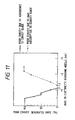
- Fig. 11 is a graph showing a relation between the bias voltage applied to the electricity removing needle and the sheet conveyance on the convey guide.
- the voltage of the electricity removing needle should be maintained between -1.1 kV and -1.3 kV to prevent the poor conveyance of the sheet due to the electrostatic absorption of the sheet to the convey guide and the poor absorption.
- the sheet conveyance is stabilized to prevent the poor image due to the "fixing offset” and the "transfer void" under the high humidity condition.
- the above-mentioned "trail end splash” and/or the poor separation of the second sheet tip end occur.
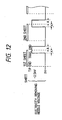
- the potential applied to the electricity removing needle 6 is changed or switched between -2.5 kV (potential for preventing the occurrence of the trail end splash) and 0 kV (potential for removing the electricity moderately without occurring the "fixing offset” and the "transfer void” under the high humidity condition).
- the potential is switched when the paper sheet has just passed through the electricity removing needle.
- a sequence for effecting the switching is shown in Fig. 12 . As shown in Fig.
- the potential applied to the electricity removing needle 6 is switched so that the potential on the sheet becomes 0 kV from the tip end to the vicinity of a central portion of the sheet (ahead of the trail end) and becomes -2.5 kV in the vicinity of the trail end.
- the switching timing x of the potential from 0 kV to -2.5 kV is a point that the rear margin of the sheet reaches the rear half of the transfer nip, and the switching value can be calculated as follows:
- the width m of the rear margin is 5 mm
- the width n of the transfer nip is 2.5 mm
- the sheet conveying speed is 40 mm/sec
- a symbol A shown in Fig. 12 (i.e., timing for returning from -2.5 kV to 0 kV) can be selected as any time after the trail end of the sheet is separated from the photosensitive drum sufficiently, and, in this case, the timing is selected to the time point when the trail end of the sheet is spaced apart from the electricity removing needle by 10 mm. In this way, it is possible to prevent the poor image such as the image deterioration and the trail end smudge due to the "trail end splash" without occurring the "transfer void" under the high humidity condition.
- the voltage of the electricity removing needle is applied to a rear end image area of 11.35 mm (16.35 mm - 5 mm) of the transfer sheet.
- the fixing offset did not occur. The reason is considered that, since the bias voltage is applied to the narrow area of the sheet, the fixing roller performs the next revolution soon, and, thus, if the amount of toner transferred to the fixing roller is small, the image contamination becomes unnoticeable. As a result, the fixing offset became an acceptable level.
- FIG. 18 An example of an image forming apparatus in which the images can be printed on both surfaces of the sheet is shown in Fig. 18 .
- Fig. 18 the same elements as those shown in Fig. 1 are designated by the same reference numerals.
- the drum is exposed by an exposure device 28, thereby forming an electrostatic latent image on the drum.
- the latent image is developed by a developing device 30 to form a toner image.
- the toner image is transferred onto the sheet 19, and, then, the sheet is sent to a fixing device 13, where the toner image is fixed to the sheet, thereby obtaining the image.
- the sheet discharged from the fixing device 13 is directed to a downward direction by a rotatable flapper 37 to reach a reverse rotation roller 40 along guides 39.
- the sheet 19 is temporarily entered between guides 41 by normal rotation of the reverse rotation roller 40 and then is sent to a pair of convey rollers 43 along guides 42 by reverse rotation of the reverse rotation roller 40 with the surface of the sheet turned over.
- the pair of convey rollers 43 convey the sheet 19 to the pair of convey rollers 33, and, then, the sheet 19 (particularly, the other surface thereof on which an image is not formed) is again subjected to the image transferring process and the fixing process.
- the sheet After the image was fixed to the other surface (second surface) of the sheet 19, the sheet is directed to an upward direction by the flapper 37 to reach a pair of discharge rollers 45 along guides 38 and then is discharged onto a sheet discharge tray 46.
- the reference numeral 47 denotes a frame of the image forming apparatus.
- an operation panel is provided with a selection switch by which an operator can select a one-face image formation mode in which the image is formed on a single surface of the sheet or a both-face image formation mode in which the images are formed on both surfaces of the sheet.
- a selection switch by which an operator can select a one-face image formation mode in which the image is formed on a single surface of the sheet or a both-face image formation mode in which the images are formed on both surfaces of the sheet.
- Figs. 13A to 13C show sequences for applying the voltage to the electricity removing needle to prevent the formation of curvature in the sheet and to prevent the "transfer void" under the high humidity condition.
- Fig. 13A shows a fundamental or base sequence in which the potential of -2.5 kV is applied to the electricity removing needle regarding a trail end area of the first surface of the sheet as is in the first embodiment.
- the potential of -1.5 kV (required for the sheet separation) is applied to the electricity removing needle.
- the sheet can be separated positively.
- the potential of the electricity removing needle is maintained to 0 V.
- the OFF timing z for making the potential applied to the electricity removing needle 0 V, it is not necessary to consider the transfer void since the transfer void does not occur under the high humidity condition because the sheet has already been passed through the fixing device.
- the OFF timing should have duration sufficient to prevent the influence upon the image.
- the OFF timing has duration corresponding to a length of a tip end margin of the sheet not to overlap with the image on the sheet. In the illustrated embodiment, since the length of the tip end margin is 5 mm, the OFF timing z is also 5 mm.
- a sequence shown in Fig. 13B or a sequence shown in Fig. 13C may be used.
- Fig. 13B unlike to Fig. 13A having three potential levels, only two potential levels (0 V and -2.5 kV) are used so that the potential level greater than 0 V is applied to the electricity removing needle regarding the trail end area of the first surface of the sheet and the tip end area of the second surface of the sheet.
- Fig. 13B unlike to Fig. 13A having three potential levels, only two potential levels (0 V and -2.5 kV) are used so that the potential level greater than 0 V is applied to the electricity removing needle regarding the trail end area of the first surface of the sheet and the tip end area of the second surface of the sheet.
- the great potential level was applied to the electricity removing needle regarding the tip end area of the second surface of the sheet.
- a sheet having small resiliency such as a sheet having a weight of 60 g/m 2 or less
- Fig. 14 shows an image forming apparatus according to a third embodiment of the present invention.
- the same elements as those in the first and second embodiments are designated by the same reference numerals and detailed explanation thereof will be omitted.
- This third embodiment shows an example that a convey guide for guiding the transfer sheet (transfer material) after transferring and before fixing has a conductive member for absorbing the sheet.
- the convey guide comprises a plurality of electrically insulation resin ribs 27, and earthed metal plates 11.
- the voltage from the power source 9 is applied to the electricity removing needle 6, which voltage is controlled by the control portion 138 including the CPU 139 and the like.
- Fig. 15 shows the case where the image is formed on the single surface of the sheet (one-face image formation mode).
- the potential applied to the electricity removing needle is maintained to -1.2 kV from the tip end of the sheet to the vicinity of the trail end of the sheet so that the sheet is prevented from being absorbed to the convey guide electrostatically, thereby preventing the sheet jam due to the sheet absorption.
- the potential of -2.5 kV is applied to the electricity removing needle to prevent the occurrence of the "trail end splash”.
- Fig. 16 shows the case where the images are formed on both surfaces of the sheet (both-face image formation mode).
- the potential of -2.5 kV is applied to the electricity removing needle regarding the trail end areas of the first and second surfaces of the sheet and the tip end area of the second surface of the sheet, thereby preventing the adhesion of the sheet to the convey guide.
- the timing for switching the potential applied to the electricity removing needle between the trail end area of the first surface of the sheet and the tip end area of the second surface of the sheet is the same as the switching timing in the second embodiment.
- the value of the potential may be changed in dependence upon the image and/or sheet convey feature.
- the switching of the voltage value applied to the electricity removing needle while an example that the voltage value is immediately changed (in a digital fashion) was explained, the switching of the voltage value (other than the switching of the voltage from the low voltage to the high voltage regarding the trail end area of the sheet) may be effected in an analogue fashion or with certain time constant.
- the voltage applied to the electricity removing needle is maintained to -2.5 kV while the sheet is not passed above the electricity removing needle 6.
- the great voltage is applied to the electricity removing needle while the sheet is not passed above the electricity removing needle, there is a danger of charging the photosensitive drum by the electricity removing needle.
- a charge roller such as a first charge (for charging the photosensitive drum) having small potential converging ability is used or when the current flowing into the charger is reduced to prevent the occurrence of ozone (i.e., charging ability is decreased), the charged history or record generated by the electricity removing needle cannot often be erased.
- the charged history of the electricity removing needle remains as it is, since the uniform charging cannot be achieved along a longitudinal direction of the photosensitive drum, the poor image including white stripes will occur.
- the voltage applied to the electricity removing needle is maintained to -1.2 kV while the sheet is not passed above the electricity removing needle.
- the rise of the high voltage source is sufficiently fast under the operating condition of the apparatus, it is effective that the voltage applied to the electricity removing needle is maintained to 0 V while the sheet is not passed above the electricity removing needle, in the one-face image formation mode ( Fig. 20 ) and in the both-face image formation mode ( Fig. 21 ).
- Fig. 23 shows a laser printer 101 according to the fourth embodiment.
- the laser printer 101 includes a deck 36 containing recording sheets (transfer sheets) 19 therein, a deck sheet presence/absence sensor 103 for detecting presence/absence of the sheet 19 in the deck 36, a sheet size detection sensor 104 (constituted by a plurality of micro-switches which will be described later) for detecting a size of the transfer sheet 19 contained in the deck 36, a pick-up roller 25 for picking up the sheet(s) 19 from the deck 36, a deck sheet supply roller 106 for conveying the sheet(s) 19 picked up from the deck by the pick-up roller 25, and a retard roller 107 associated with the deck sheet supply roller 106 to prevent the double-feed of sheets.
- a deck 36 containing recording sheets (transfer sheets) 19 therein
- a deck sheet presence/absence sensor 103 for detecting presence/absence of the sheet 19 in the deck 36
- a sheet size detection sensor 104 (constituted by a plurality of micro-switches which will be
- a sheet supply sensor 108 for detecting a sheet conveying condition from a both-face reverse rotation portion (described later)
- a sheet supply convey roller 33 for further conveying the transfer sheet 19 in a downstream direction
- a pair of regist rollers 31 for conveying the transfer sheet 19 synchronously with the photosensitive drum 1
- a pre-regist sensor 110 for detecting a conveying condition of the sheet 19 to the paired regist rollers 31.
- a convey guide 10 a fixing portion including a fixing roller 20 having a heating halogen heater therein for thermally fixing the toner image to the transfer sheet 19 and a pressure roller 22 urged against the fixing roller, a fixing sheet discharge sensor 116 for detecting a conveying condition of the sheet from the fixing portion, and a both-face flapper 37 for switching a sheet path between a sheet discharge portion and a both-face reverse rotation portion.
- a sheet discharge sensor 118 for detecting a sheet conveying condition from the sheet discharge portion, and a pair of sheet discharge rollers 45 for discharging the transfer sheet 19.
- the both-face reverse rotation portion for reversing (i.e., turning over) the sheet having one surface on which the image was formed and for re-supplying the sheet to the image forming portion again includes a pair of reverse rotation rollers 40 for switching-back the transfer sheet 19 by normal/reverse rotation thereof, a D-cut roller 190 for conveying the transfer sheet 19 from a lateral regist portion (not shown) where a lateral position of the sheet is determined, a both-face sensor 122 for detecting a sheet conveying condition from the both-face reverse rotation portion, and a pair of both-face convey rollers 43 for conveying the transfer sheet 19 from the both-face reverse rotation portion to a sheet supply portion.
- the scanner portion 28 comprises a laser unit 125 for emitting a laser beam modulated in response to an image signal sent from an external device 141 (described later), a polygon mirror 126 and a scanner motor 127 for scanning the photosensitive drum 1 with the laser beam from the laser unit 125, a group of lenses 128, and a reflection mirror 129.
- the process cartridge 112 includes the photosensitive drum 1, a first charger 131, a developing sleeve 132 and a toner containing container 133 which are required for effecting the known electrophotographic process, which process cartridge can be removably mounted on the laser printer.
- a high voltage source 137 serves to supply desired voltage to the first charger 131, developing sleeve 132, transfer roller 4 and electricity removing needle 6.
- a main motor 136 serves to supply a driving force to various elements further, a printer control portion 139 for controlling the laser printer 101 comprises an MPU (microcomputer) 139 including a RAM 139a, a ROM 139b, a timer 139c and an I/O (input/output) portion 139d, and various I/O control circuits (not shown).
- MPU microcomputer
- the printer control portion 139 is connected to the external device 141 such as a personal computer through an interface 140.
- a synchronous signal (referred to as "VSYNC signal” hereinafter) of an image output (described later) in a vertical direction is also sent from the external device 141 to the printer control portion 139 through the interface 140.
- Fig. 22 is a circuit diagram of the high voltage source for the electricity removing needle and therearound.
- the high voltage for the electricity removing needle is obtained by voltage-doubling AC voltage generated at an output terminal of an inverter transformer 143 by four times by diodes (148 - 151) and capacitors (144 - 147), and is supplied to the electricity removing needle through a shorting protection resistor 152.
- the output voltage of the electricity removing needle is voltage-divided and detected by a resistor 156 and a resistor 163, and the input voltage of the inverter transformer 143 is controlled by a power amplifier comprised of resistors (159, 161), a transistor 157, an aluminium electrolytic capacitor 158 and a protection diode 160 so that the input voltage is equalized to reference voltage inputted to positive and negative terminal of an operation amplifier 162.
- the reference voltage is obtained by voltage-dividing +5 V by resistors (166 - 168).
- Fig. 35 shows a rising wave form of the high voltage of the electricity removing needle.
- a curve a indicates a wave form when the resistor 169 and capacitor 170 are not provided.
- a curve c in Fig. 35 indicates a wave form when the value of the resistor 169 is small and/or the capacity of the capacitor 170 is great. In this case, the wave form has no overshoot but has slow rise.
- the value of the resistor 160, the capacity of the capacitor and the resistance value of the composite resistor are selected so that a wave form has moderate rise and does not include the excessive overshoot as is in the wave form a.
- a transistor 153 for driving the inverter transformer 143 has a base connected to an oscillation circuit 154 through a resistor 142.
- a diode 155 constitutes a snapper circuit.
- a transistor 164 serves to effect ON/OFF of the high voltage of the electricity removing needle and has a base connected to the I/O port 139d of the MPU 139 of the printer control portion 138 through a resistor 165. If a level of the connected port is HIGH, the transistor 164 is turned ON, with the result that the positive terminal of the operation amplifier 162 becomes ground potential level, thereby changing the high voltage of the electricity removing needle to an OFF condition. On the other hand, if the level of the connected port is LOW, the transistor 164 is turned OFF, with the result that the high voltage of the electricity removing needle is outputted.
- a transfer high voltage source 174 serves to supply high voltage to the transfer roller 4.
- the sheet size detection sensor 104 is constituted by micro-switches (175 - 177) and resistors (178 - 180). A level of the I/O port connected to the depressed micro-switch becomes LOW, and a level of the I/O port connected to the non-depressed micro-switch becomes HIGH. Thus, by combination of HIGH/LOW of three ports, the size of the transfer sheet 19 being printed can be detected, thereby controlling the output timing of the high voltage of the electricity removing needle which will be described later.
- Fig. 24 is a timing chart according to the illustrated embodiment.
- a point A indicates an upstream end of the nip between the photosensitive drum 1 and the transfer roller 4
- a point B indicates a downstream end of said nip
- a point C indicates a position immediately above the electricity removing needle 6.
- a distance between the points A and B is L1 (mm) and a distance between the points B and C is M (mm).
- the transfer sheet (recording sheet) is conveyed through these three points at a speed of V (mm/sec).
- a width of a non-image area of the tip end of the recording sheet 19 is N1 (mm)
- a width of a non-image area of the trail end of the recording sheet 19 is N2 (mm)
- a length of the recording sheet is P (mm). The length of the recording sheet is detected on the basis of a signal from the sheet size detection sensor 104.
- the drive signal for the high voltage of the electricity removing needle (I/O port connected to the base of the transistor 164) is turned ON after a time T1 (sec) is elapsed from a rising edge of the VSYNC signal, thereby rising the high voltage of the electricity removing needle to -2.7 kV before the tip end of the recording sheet reaches the point A.
- the drive signal is turned OFF after a time T2 (sec) so that the high voltage of the electricity removing needle becomes 0 V before the image area of the recording sheet 19 reaches the nip.
- the high voltage is applied to the electricity removing needle in a condition that the image area exists in the nip
- the current flowing onto the recording sheet (as charges) from the transfer roller 4 to effect the transferring of the toner image cannot be held on the recording sheet 19 due to the reduction of resistance of the recording sheet 19 to escape to the electricity removing needle, thereby causing the so-called "transfer void".
- the reason for setting the above times is to prevent the occurrence of the transfer void.
- the control for the high voltage of the electricity removing needle regarding the trail end of the recording sheet 19 is effected in the similar manner.
- T ⁇ 4 Tt + ( P + L + M ) / V .
- Fig. 25 is a flow chart showing the control according to the illustrated embodiment.
- the size of the recording sheet is detected by the sheet size detection sensor 104 (step S100), and the variable P is substituted for numeral on the basis of a sheet size detection result to calculate the timing T3 (sec) and the timing T4 (sec) (step S101).
- a timer TM is reset and a counter is started (step S103).
- step S104 If the timer TM is T1 ⁇ TM ⁇ T2 (step S104) or T3 ⁇ TM ⁇ T4 (step S105), the high voltage of the electricity removing needle is turned ON (step S107); otherwise, the high voltage of the electricity removing needle is turned OFF (step S106). If the timer TM is T4 ⁇ TM, the control is finished (step S108).
- the charge can be fully removed from the tip end of the recording sheet to separate the tip end from the photosensitive drum effectively, and the charge can be forcibly removed from the trail end area of the recording sheet so that the electrostatic force for holding the toner on the recording sheet can be maintained and the "trail end splash" for moving the trail end of the sheet together with the photosensitive drum can be prevented.
- a fifth embodiment of the present invention will be explained with reference to Fig. 26 showing a circuit diagram of the high voltage source for the electricity removing needle and therearound.
- This fifth embodiment differs from the fourth embodiment in the point that the reference voltage inputted to the negative terminal of the operation amplifier 162 is made variable so that the output value of the high voltage of the electricity removing needle can be changed or switched.
- a transistor 172 having a base connected to the I/O port 139d of the MPU 139 through a resistor 173 is turned ON (i.e., when the I/O port 139d becomes HIGH level)
- a resistor 171 is connected to a resistor 167 in parallel, thereby decreasing the reference voltage.
- the high voltage of the electricity removing needle has a minus value, the absolute value of the high voltage output of the electricity removing needle is increased.
- Fig. 27 is a timing chart according to the illustrated embodiment.
- the drive signal for the high voltage of the electricity removing needle is turned ON after a time T5 (sec) is elapsed from a rising edge of the VSYNC signal, thereby rising the high voltage of the electricity removing needle to -1.2 kV before the tip end of the recording sheet 19 reaches the point A.
- the high voltage (of the electricity removing needle) of -1.2 kV is voltage sufficient to separate the tip end of the recording sheet 19 from the photosensitive drum 1 while keeping the electrostatic force for holding the toner on the recording sheet 19 and without occurring the transfer void.
- the output switching signal is turned ON at the timing T3 (sec) when the image area leaves the point B, thereby increasing the high voltage of the electricity removing needle to -2.7 kV.
- the high voltage drive signal and the input/output change signal are turned ON at the timing T4 (sec) when the trail end of the recording sheet 19 leaves the point C, thereby turning OFF the high voltage of the electricity removing needle.
- Fig. 28 is a flow chart showing the control according to the illustrated embodiment. Steps (S120 - S123) from START to reset/start of the timer TM are the same as those in the fourth embodiment. Thereafter, if the timer TM is T5 ⁇ TM ⁇ T4 (True) (step S124), the high voltage drive signal is turned ON; whereas, if the result in the step S124 is False, the high voltage drive signal is turned OFF (step S126).
- step S127 the input/output change signal is turned ON (step S128); whereas, if the result in the step S127 is False, the input/output change signal is turned OFF (step S129). And, if the timer is T4 ⁇ TM, the control is finished (step S130).
- the charge can be fully removed from the tip end area of the recording sheet to separate the tip end from the photosensitive drum effectively, and the charge can be forcibly removed from the trail end area of the recording sheet so that the electrostatic force for holding the toner on the recording sheet can be maintained and the "trail end splash" for moving the trail end of the sheet together with the photosensitive drum can be prevented.
- a circuit diagram of the high voltage source for the electricity removing needle and therearound is the same as that of the fourth embodiment.
- Fig. 29 is a timing chart according to the illustrated embodiment.
- the sixth embodiment differs from the fourth embodiment in the points that a timing (T6) for falling the high voltage of the electricity removing needle regarding the tip end area of the recording sheet 19 (T2 in the fourth embodiment) is delayed so that the high voltage of the electricity removing needle becomes -1.2 kV or less until the image area of the recording sheet reaches the point A, and that a timing (T7) for rising the high voltage of the electricity removing needle regarding the trail end area of the recording sheet 19 (T3 in the fourth embodiment) is fastened so that the high voltage of the electricity removing needle is maintained below -1.2 kV until the image area of the recording sheet leaves the point B.
- a flow chart for effecting the control according to the illustrated embodiment is the same as that of the fourth embodiment shown in Fig. 25 , except that T2 is changed to T6 and T3 is changed to T7.
- the time duration for applying the high voltage to the electricity removing needle regarding the tip and trail end areas of the recording sheet is lengthened, thereby improving the electricity removing ability.
- Fig. 30 is a circuit diagram of the high voltage source for the electricity removing needle and therearound, according to the seventh embodiment.
- the seventh embodiment differs from the fourth embodiment in the point that the resistor 156 for detecting the output voltage is connected to a voltage doubler circuit, other than the output portion.
- the resistor 156 is connected to a position where the AC voltage generated at the output terminal of the inverter transformer 143 is doubled twice and voltage is 1/2 of the output high voltage.
- the control of the output voltage is effected by detecting the voltage in the rectifier portion smaller than the output voltage regarding the high voltage source for generating the high voltage applied to the electricity removing needle by using the constant voltage doubler system, even when the resistance value of the detection resistor is the same, the electric power applied to the detection resistor can be reduced, thereby fastening the rise of the high voltage output. Further, in some cases, since the maximum acceptable voltage or maximum acceptable electric power of the detection resistor can be reduced, the apparatus can be made cheaper.
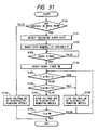
- FIG. 31 is a flow chart according to the eighth embodiment.
- the eighth embodiment differs from the fourth embodiment in the point that the same control as the fourth embodiment is effected regarding the second surface of the recording sheet in the both-face image formation mode (steps S150 - S159) and the high voltage of the electricity removing needle is turned OFF in the one-face image formation mode and regarding the first surface of the recording sheet in the both-face image formation mode (step S160).
- bias voltage applied to the electricity removing needle is particularly effective to the separation of the thin sheet from the photosensitive drum 1.
- the thin sheets will be widely used from the view point of protection of wood resources.
- the bias voltage applied to the electricity removing needle is changed in accordance with a thickness of a sheet.
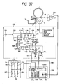
- Fig. 32 is a circuit diagram according to the ninth embodiment.
- the reference numeral 201 denotes a sheet thickness sensor of light reflection type or light permeable type.
- Z4D-AO1 sensor sold by Omron can be used to accurately measure the thickness of the sheet by using triangular distant measurement.
- the sheet thickness sensor 201 is disposed in the sheet convey path at an upstream side of the transfer position. An output from the sensor which is in an analogue form is received by an A/D converter 202 of the CPU 138.
- a step S201 the thickness of the sheet is checked. If the sheet thickness is smaller than a predetermined value, in a step S202, the signal is outputted from the I/O port 139d to increase the bias voltage. On the other hand, if the sheet thickness is greater than the predetermined value, in a step S203, the signal is outputted from the I/O port 139d to decrease the bias voltage.
- the voltage switching method is the same as the above-mentioned fifth embodiment.
- the bias voltage is applied to the electricity removing needle.
- the sheet thickness is checked. If the sheet thickness is smaller than a predetermined value, in a step S204, predetermined bias voltage is applied to the electricity removing needle. On the other hand, if the sheet thickness is greater than the predetermined value, in a step S205, any bias voltage is not applied to the electricity removing needle.
- the operator may previously input the kind of sheet through the operation portion or the sheet thickness may be determined from a mark provided on a sheet cassette containing a predetermined kind of sheets.
- the tip end of the sheet can effectively be separated from the image bearing member.
- the guide for guiding the sheet after transferring and before fixing even when there is provided the guide for guiding the sheet after transferring and before fixing, the jam due to the electrostatic absorption of the sheet to the guide can be prevented.
- the level of the bias voltage applied to the electricity removing needle in accordance with the thickness of the transfer sheet the kinds of sheets which can be handled is increased, and, regarding the thick sheets capable of being separated from the image bearing member by the curvature separating action, since the excessive bias voltage is not applied to the needle, the electric power can be saved.
- the both-face image formation mode by changing the bias voltage between the first surface and the second surface of the sheet, the electric power can be saved while maintaining the adequate separating ability.
Landscapes
- Physics & Mathematics (AREA)
- General Physics & Mathematics (AREA)
- Electrostatic Charge, Transfer And Separation In Electrography (AREA)
- Paper Feeding For Electrophotography (AREA)
- Control Or Security For Electrophotography (AREA)
Claims (18)
- Appareil de formation d'image destiné à former une image sur un support de report (19) transporté dans une direction de transport à travers l'appareil de formation d'image, l'appareil de formation d'image comportant :un élément porteur d'image (1) destiné à porter une image en toner ;un dispositif (4) de charge pour un report destiné à reporter l'image en toner de l'élément porteur d'image (1) sur une surface du support de report (19) ;un élément (6) de suppression d'électricité destiné à supprimer l'électricité du support de report (19) afin de séparer le support de report (19) de l'élément porteur d'image (1) ; etun moyen (9) destiné à appliquer un potentiel à l'élément (6) de suppression d'électricité,caractérisé en ce que ledit élément (9) d'application de potentiel est agencé pour appliquer un premier niveau de potentiel à l'élément (6) de suppression d'électricité afin de séparer la zone extrême arrière du support de report (19), par rapport à un sens de transport du support de report, de l'élément porteur d'image (1) et pour appliquer un second niveau de potentiel, qui est inférieur audit premier niveau de potentiel, à l'élément (6) de suppression d'électricité afin de séparer la zone centrale du support de report (19) de l'élément porteur d'image (1).
- Appareil de formation d'image selon la revendication 1, dans lequel le moyen (9) d'application de potentiel est agencé pour appliquer un troisième niveau de potentiel, qui est supérieur audit deuxième niveau de potentiel, à l'élément (6) de suppression d'électricité afin de séparer la zone extrême avant du support de report (19), par rapport au sens de transport du support de report, de l'élément porteur d'image (1).
- Appareil de formation d'image selon la revendication 2, dans lequel le moyen (9) d'application de potentiel est agencé pour appliquer le premier niveau de potentiel à l'élément (6) de suppression d'électricité afin de séparer la zone extrême arrière du support de report (19) de l'élément porteur d'image (1) pendant un temps plus long que l'application du troisième niveau de potentiel à l'élément (8) de suppression d'électricité pour séparer la zone extrême avant du support de report (19) de l'élément porteur d'image 1.
- Appareil de formation d'image selon la revendication 2 ou la revendication 3, dans lequel le premier niveau de potentiel est identique au troisième niveau de potentiel.
- Appareil de formation d'image selon l'une quelconque des revendications 2 à 4, dans lequel le troisième niveau de potentiel est établi de façon à être supérieur au deuxième niveau de potentiel lorsque l'épaisseur du support de report (19) est inférieure à une valeur prédéterminée et le troisième niveau de potentiel est établi de façon à être identique au deuxième niveau de potentiel lorsque l'épaisseur du support de report (19) est supérieure à ladite valeur prédéterminée.
- Appareil de formation d'image selon l'une quelconque des revendications 1 à 4, dans lequel le moyen (9) d'application de potentiel est agencé pour appliquer un potentiel à l'élément (6) de suppression d'électricité lorsque l'épaisseur du support de report (19) est inférieure à une valeur prédéterminée, et pour ne pas appliquer un potentiel lorsque l'épaisseur du support de report (19) est supérieure à ladite valeur prédéterminée.
- Appareil de formation d'image selon l'une quelconque des revendications précédentes, lequel appareil de formation d'image peut être mis en oeuvre pour reporter une image sur une seconde surface du support de report (19) après avoir reporté une image sur la première surface dudit support de report (19), et dans lequel le moyen (9) d'application de potentiel est agencé de manière que, lorsque l'image est reportée sur la seconde surface du support de report (19), un quatrième niveau de potentiel soit appliqué pour séparer la zone extrême avant du support (19) de report, par rapport au sens de transport du support de report, de l'élément porteur d'image (1), qui est supérieur à un cinquième niveau de potentiel pour enlever la zone centrale dudit support de report (19) de l'élément porteur d'image (1).
- Appareil de formation d'image selon la revendication 7 lorsqu'elle dépend de la revendication 2, dans lequel le moyen (9) d'application de potentiel est agencé de façon que le quatrième niveau de potentiel soit supérieur au troisième niveau de potentiel.
- Appareil de formation d'image selon la revendication 7 ou 8, lequel appareil de formation d'image peut être mis en oeuvre pour reporter une image sur la seconde surface du support de report (19) après avoir reporté une image sur la première surface dudit support de report (19), et dans lequel le moyen (9) d'application de potentiel est agencé afin que, lorsqu'une image est reportée sur la seconde surface du support de report (19), un sixième niveau de potentiel, qui est supérieur audit cinquième niveau de potentiel, soit appliqué pour séparer la zone extrême arrière du support de report (19), par rapport au sens de transport du support de report, de l'élément porteur d'image (1).
- Appareil de formation d'image selon l'une quelconque des revendications 7 à 9, dans lequel le moyen (9) d'application de potentiel est agencé afin que, lorsque l'image est reportée sur la première surface du support de report (19), le niveau de potentiel appliqué à l'élément (6) de suppression d'électricité pour séparer ladite zone extrême arrière de l'élément porteur d'image (1), soit supérieur au niveau de potentiel appliqué pour séparer ladite zone centrale.
- Appareil de formation d'image selon l'une quelconque des revendications précédentes, dans lequel le moyen (9) d'application de potentiel est agencé de manière que le niveau de potentiel appliqué à l'élément (6) de suppression d'électricité pour séparer les zones sans image du support de report (19) de l'élément porteur d'image (1) soit supérieur au niveau de potentiel pour séparer une zone d'image dudit support de report (19) de l'élément porteur d'image (1).
- Appareil de formation d'image selon la revendication 11, dans lequel un temps pour commencer l'élévation d'une tension appliquée audit élément (6) de suppression d'électricité précède un temps au moment où le support de report (19) atteint une position de report, afin que ledit niveau de potentiel devienne inférieur à une valeur prédéterminée par ladite zone d'image du support de report (19).
- Appareil de formation d'image selon l'une quelconque des revendications précédentes, dans lequel le moyen (9) d'application de potentiel est agencé de manière que, lorsqu'un potentiel est appliqué audit élément de suppression d'électricité, un léger dépassement du potentiel soit généré.
- Appareil de formation d'image selon l'une quelconque des revendications précédentes, dans lequel le moyen (9) d'application de potentiel est agencé pour générer la tension appliquée à l'élément (6) de suppression d'électricité par un doublage de tension constant, et la commande de ladite tension appliquée est effectuée en détectant une tension inférieure à ladite tension appliquée dans une partie de redressement du moyen d'application de potentiel.
- Appareil de formation d'image selon l'une quelconque des revendications précédentes, dans lequel le diamètre dudit élément porteur d'image est de 40 mm ou moins.
- Appareil de formation d'image selon l'une quelconque des revendications précédentes, dans lequel le dispositif (4) de charge pour le report est agencé de façon à entrer en contact avec une surface du support de report transporté entre ledit élément porteur d'image (1) et ledit dispositif (4) de charge pour le report, opposée à la surface du support de report (19) qui est tournée vers ledit élément porteur d'image (1).
- Appareil de formation d'image selon la revendication 16, dans lequel ledit dispositif (4) de charge pour le report peut être mis en contact avec ledit élément porteur d'image (1).
- Appareil de formation d'image selon l'une quelconque des revendications précédentes, dans lequel le dispositif (4) de charge pour le report a la forme d'un rouleau.
Applications Claiming Priority (4)
| Application Number | Priority Date | Filing Date | Title |
|---|---|---|---|
| JP62608/95 | 1995-03-22 | ||
| JP6260895 | 1995-03-22 | ||
| JP271281/95 | 1995-10-19 | ||
| JP27128195A JP3184750B2 (ja) | 1995-03-22 | 1995-10-19 | 画像形成装置 |
Publications (3)
| Publication Number | Publication Date |
|---|---|
| EP0733956A2 EP0733956A2 (fr) | 1996-09-25 |
| EP0733956A3 EP0733956A3 (fr) | 1998-07-08 |
| EP0733956B1 true EP0733956B1 (fr) | 2009-01-21 |
Family
ID=26403653
Family Applications (1)
| Application Number | Title | Priority Date | Filing Date |
|---|---|---|---|
| EP96301941A Expired - Lifetime EP0733956B1 (fr) | 1995-03-22 | 1996-03-21 | Appareil de formation d'images |
Country Status (4)
| Country | Link |
|---|---|
| US (1) | US5926683A (fr) |
| EP (1) | EP0733956B1 (fr) |
| JP (1) | JP3184750B2 (fr) |
| DE (1) | DE69637819D1 (fr) |
Families Citing this family (20)
| Publication number | Priority date | Publication date | Assignee | Title |
|---|---|---|---|---|
| JP2000019856A (ja) * | 1998-07-03 | 2000-01-21 | Fuji Xerox Co Ltd | 画像形成装置 |
| JP2002040816A (ja) * | 2000-07-28 | 2002-02-06 | Canon Inc | 画像形成装置 |
| JP4467844B2 (ja) * | 2000-08-11 | 2010-05-26 | キヤノン株式会社 | 画像形成装置 |
| JP4366024B2 (ja) | 2001-03-16 | 2009-11-18 | キヤノン株式会社 | 画像形成装置 |
| JP4557455B2 (ja) * | 2001-03-30 | 2010-10-06 | キヤノン株式会社 | 画像形成装置 |
| US7280798B2 (en) * | 2004-03-09 | 2007-10-09 | Canon Kabushiki Kaisha | Image forming apparatus with conveying device urging a recording material toward a charge eliminating member |
| JP2006146117A (ja) * | 2004-10-20 | 2006-06-08 | Brother Ind Ltd | 画像形成装置 |
| JP5046262B2 (ja) * | 2004-11-30 | 2012-10-10 | 京セラドキュメントソリューションズ株式会社 | 画像形成装置 |
| JP4942151B2 (ja) * | 2005-04-25 | 2012-05-30 | キヤノン株式会社 | 画像形成システム及び画像形成装置 |
| JP2007127677A (ja) * | 2005-10-31 | 2007-05-24 | Ricoh Co Ltd | ガイド部材および画像形成装置 |
| JP4854071B2 (ja) * | 2006-02-22 | 2012-01-11 | 京セラミタ株式会社 | 画像形成装置 |
| JP5044170B2 (ja) * | 2006-08-29 | 2012-10-10 | 京セラドキュメントソリューションズ株式会社 | 画像形成装置 |
| JP6124522B2 (ja) * | 2011-09-13 | 2017-05-10 | キヤノン株式会社 | 高圧電源装置及び画像形成装置 |
| JP6047980B2 (ja) | 2012-07-26 | 2016-12-21 | ブラザー工業株式会社 | 記録シートガイド構造およびカートリッジ |
| JP2014048441A (ja) * | 2012-08-31 | 2014-03-17 | Kyocera Document Solutions Inc | 画像形成装置 |
| JP6021709B2 (ja) * | 2013-03-26 | 2016-11-09 | 京セラドキュメントソリューションズ株式会社 | 画像形成装置 |
| JP6759013B2 (ja) * | 2015-10-09 | 2020-09-23 | シャープ株式会社 | 転写装置及び画像形成装置 |
| US9791809B2 (en) | 2015-10-09 | 2017-10-17 | Sharp Kabushiki Kaisha | Transfer device and image forming apparatus |
| JP2019105691A (ja) * | 2017-12-11 | 2019-06-27 | コニカミノルタ株式会社 | 画像形成装置および距離制御方法 |
| JP2020071442A (ja) * | 2018-11-02 | 2020-05-07 | コニカミノルタ株式会社 | 画像形成装置、搬送枚数調整方法、およびコンピュータプログラム |
Family Cites Families (12)
| Publication number | Priority date | Publication date | Assignee | Title |
|---|---|---|---|---|
| US3620615A (en) * | 1968-12-31 | 1971-11-16 | Xerox Corp | Sheet stripping apparatus |
| JPS5422837A (en) * | 1977-07-21 | 1979-02-21 | Ricoh Co Ltd | Charge control of copying apparatus for zerography |
| US4728991A (en) * | 1984-09-19 | 1988-03-01 | Canon Kabushiki Kaisha | Image forming apparatus |
| JPS61162073A (ja) * | 1985-01-10 | 1986-07-22 | Canon Inc | 画像形成装置 |
| US4739363A (en) * | 1985-03-26 | 1988-04-19 | Canon Kabushiki Kaisha | Image forming apparatus |
| JPS61262750A (ja) * | 1985-05-17 | 1986-11-20 | Canon Inc | 画像形成装置 |
| JPH01269969A (ja) * | 1988-04-21 | 1989-10-27 | Canon Inc | 画像形成装置 |
| JPH0419976A (ja) * | 1990-05-11 | 1992-01-23 | Fujitsu Ltd | パッケージの接続構造 |
| JP2964544B2 (ja) * | 1990-05-15 | 1999-10-18 | キヤノン株式会社 | 画像形成装置 |
| US5339144A (en) * | 1990-08-31 | 1994-08-16 | Sharp Kabushiki Kaisha | Recording paper separating device with constant current control |
| JPH04268583A (ja) * | 1991-02-22 | 1992-09-24 | Canon Inc | 帯電装置 |
| JP3223004B2 (ja) * | 1993-09-21 | 2001-10-29 | 株式会社東芝 | 画像形成装置 |
-
1995
- 1995-10-19 JP JP27128195A patent/JP3184750B2/ja not_active Expired - Fee Related
-
1996
- 1996-03-20 US US08/618,763 patent/US5926683A/en not_active Expired - Lifetime
- 1996-03-21 EP EP96301941A patent/EP0733956B1/fr not_active Expired - Lifetime
- 1996-03-21 DE DE69637819T patent/DE69637819D1/de not_active Expired - Lifetime
Also Published As
| Publication number | Publication date |
|---|---|
| DE69637819D1 (de) | 2009-03-12 |
| US5926683A (en) | 1999-07-20 |
| EP0733956A3 (fr) | 1998-07-08 |
| JP3184750B2 (ja) | 2001-07-09 |
| JPH08320620A (ja) | 1996-12-03 |
| EP0733956A2 (fr) | 1996-09-25 |
Similar Documents
| Publication | Publication Date | Title |
|---|---|---|
| EP0733956B1 (fr) | Appareil de formation d'images | |
| US5666616A (en) | Wet-type image forming apparatus for forming a condensed toner image | |
| US20040091279A1 (en) | Image forming apparatus and heat fixing apparatus | |
| JPH11219045A (ja) | 画像形成装置 | |
| US6205299B1 (en) | Image forming apparatus in which whether transfer member should be constant-current-controlled or constant-voltage-controlled is selected depending on thickness of transfer material | |
| US4772918A (en) | Current-controlled image transfer | |
| US7162173B2 (en) | Image forming apparatus using an ordered set of first, second and charging AC peak to peak voltages | |
| JP2001188405A (ja) | 画像形成装置 | |
| KR0146750B1 (ko) | 화상 형성 장치 | |
| JP2000066536A (ja) | 画像形成装置 | |
| JP3605961B2 (ja) | 画像形成装置 | |
| JP3454128B2 (ja) | 画像形成装置およびその制御方法 | |
| US20030128992A1 (en) | Image forming apparatus | |
| HK1011743A (en) | Image forming apparatus | |
| JPH11272090A (ja) | 画像形成装置 | |
| JP3598644B2 (ja) | 画像形成装置 | |
| JPH11219042A (ja) | 画像形成装置 | |
| JP3455340B2 (ja) | 画像形成装置 | |
| US6438333B1 (en) | Image forming apparatus with reduced transfer current to transfer material rear end | |
| JP3826590B2 (ja) | 画像形成装置 | |
| JP2001154513A (ja) | 画像形成装置 | |
| JP2002040816A (ja) | 画像形成装置 | |
| JP3595141B2 (ja) | 転写搬送装置 | |
| JP3510008B2 (ja) | 印刷装置 | |
| JP2004045897A (ja) | 画像形成装置 |
Legal Events
| Date | Code | Title | Description |
|---|---|---|---|
| PUAI | Public reference made under article 153(3) epc to a published international application that has entered the european phase |
Free format text: ORIGINAL CODE: 0009012 |
|
| AK | Designated contracting states |
Kind code of ref document: A2 Designated state(s): DE FR GB IT |
|
| PUAL | Search report despatched |
Free format text: ORIGINAL CODE: 0009013 |
|
| AK | Designated contracting states |
Kind code of ref document: A3 Designated state(s): DE FR GB IT |
|
| 17P | Request for examination filed |
Effective date: 19981118 |
|
| 17Q | First examination report despatched |
Effective date: 19991222 |
|
| GRAP | Despatch of communication of intention to grant a patent |
Free format text: ORIGINAL CODE: EPIDOSNIGR1 |
|
| GRAS | Grant fee paid |
Free format text: ORIGINAL CODE: EPIDOSNIGR3 |
|
| GRAA | (expected) grant |
Free format text: ORIGINAL CODE: 0009210 |
|
| RAP1 | Party data changed (applicant data changed or rights of an application transferred) |
Owner name: CANON KABUSHIKI KAISHA |
|
| AK | Designated contracting states |
Kind code of ref document: B1 Designated state(s): DE FR GB IT |
|
| REG | Reference to a national code |
Ref country code: GB Ref legal event code: FG4D |
|
| REF | Corresponds to: |
Ref document number: 69637819 Country of ref document: DE Date of ref document: 20090312 Kind code of ref document: P |
|
| REG | Reference to a national code |
Ref country code: HK Ref legal event code: WD Ref document number: 1011743 Country of ref document: HK |
|
| PLBE | No opposition filed within time limit |
Free format text: ORIGINAL CODE: 0009261 |
|
| STAA | Information on the status of an ep patent application or granted ep patent |
Free format text: STATUS: NO OPPOSITION FILED WITHIN TIME LIMIT |
|
| 26N | No opposition filed |
Effective date: 20091022 |
|
| PG25 | Lapsed in a contracting state [announced via postgrant information from national office to epo] |
Ref country code: IT Free format text: LAPSE BECAUSE OF FAILURE TO SUBMIT A TRANSLATION OF THE DESCRIPTION OR TO PAY THE FEE WITHIN THE PRESCRIBED TIME-LIMIT Effective date: 20090121 |
|
| PGFP | Annual fee paid to national office [announced via postgrant information from national office to epo] |
Ref country code: DE Payment date: 20140331 Year of fee payment: 19 |
|
| PGFP | Annual fee paid to national office [announced via postgrant information from national office to epo] |
Ref country code: GB Payment date: 20140318 Year of fee payment: 19 |
|
| PGFP | Annual fee paid to national office [announced via postgrant information from national office to epo] |
Ref country code: FR Payment date: 20140326 Year of fee payment: 19 |
|
| REG | Reference to a national code |
Ref country code: DE Ref legal event code: R119 Ref document number: 69637819 Country of ref document: DE |
|
| GBPC | Gb: european patent ceased through non-payment of renewal fee |
Effective date: 20150321 |
|
| REG | Reference to a national code |
Ref country code: FR Ref legal event code: ST Effective date: 20151130 |
|
| PG25 | Lapsed in a contracting state [announced via postgrant information from national office to epo] |
Ref country code: DE Free format text: LAPSE BECAUSE OF NON-PAYMENT OF DUE FEES Effective date: 20151001 Ref country code: GB Free format text: LAPSE BECAUSE OF NON-PAYMENT OF DUE FEES Effective date: 20150321 |
|
| PG25 | Lapsed in a contracting state [announced via postgrant information from national office to epo] |
Ref country code: FR Free format text: LAPSE BECAUSE OF NON-PAYMENT OF DUE FEES Effective date: 20150331 |