EP0734005B1 - Système de réception/gestion pour signaux numériques issus de dispositifs électroniques, et capables d'apprendre la configuration des capteurs, en particulier pour système d'alarme - Google Patents
Système de réception/gestion pour signaux numériques issus de dispositifs électroniques, et capables d'apprendre la configuration des capteurs, en particulier pour système d'alarme Download PDFInfo
- Publication number
- EP0734005B1 EP0734005B1 EP96200768A EP96200768A EP0734005B1 EP 0734005 B1 EP0734005 B1 EP 0734005B1 EP 96200768 A EP96200768 A EP 96200768A EP 96200768 A EP96200768 A EP 96200768A EP 0734005 B1 EP0734005 B1 EP 0734005B1
- Authority
- EP
- European Patent Office
- Prior art keywords
- control unit
- digital signals
- electronic control
- sensor elements
- zone
- Prior art date
- Legal status (The legal status is an assumption and is not a legal conclusion. Google has not performed a legal analysis and makes no representation as to the accuracy of the status listed.)
- Expired - Lifetime
Links
Images
Classifications
-
- G—PHYSICS
- G08—SIGNALLING
- G08B—SIGNALLING SYSTEMS, e.g. PERSONAL CALLING SYSTEMS; ORDER TELEGRAPHS; ALARM SYSTEMS
- G08B26/00—Alarm systems in which substations are interrogated in succession by a central station
- G08B26/001—Alarm systems in which substations are interrogated in succession by a central station with individual interrogation of substations connected in parallel
Definitions
- the present invention relates to a reception/management system for digital signals from electronic devices used, in particular, for alarm systems.
- the present alarm systems generally comprise an electronic control unit (referred to in the following, by the more common term “central unit”), alarm devices (such as sirens, warning horns, blinkers), specific sensors to the installed system type, telephone diallers, stabilized power supply units, which take the voltage from electrical power distribution mains, enabling or disabling devices, actuators or driver devices for motor units.
- buss connecting lines of digital type
- the installer must subdivide the area controlled by the alarm system into several zones each of which can be excluded from control independently from the other zones.
- Such a configuration is normally accomplished by means of digital signals reception/management systems of traditional type, by connecting the central unit with one or more electrical networks constituted by sensor elements, other electronic devices for auxiliary functions and sound signalling devices (which start operating in the event of a fire) by means of a star-like connection pattern, using purposely designed point-to-point lines, i.e., one line per each zone.
- the individual sensor element is suitably configured by setting purposely provided setting means said sensor element is equipped with (by acting, for example, on "DIP switches", rotary selectors, resistors).
- EP-A-0 485 878 discloses a system according to the preamble of claim 17.
- Each sensor element is defined as belonging to a well determined zone and an univocal correspondence is established between the sensor element and the zone it belongs to ("belonging zone").
- the sensor elements can be supplied as already provided with an univocal code of their own in order to identify the zone they belong to.
- One from the main drawback of the reception/management system for digital signals as disclosed above consists in the lack of flexibility of the connections and of the device installations.
- the sensor element connected with the connecting line of a determined zone can be re-assigned to another zone only by means of a direct electrical connection with the corresponding peripheral unit.
- the major difficulty consists in that the installer must be supplied with complete information as to the operations to be performed, with the consequent and unavoidable possibilities of error in system setting (due to misunderstanding, information mistakes, staff absence) and long implementation times.
- the purpose of the present invention is of providing a reception/management system for digital signals capable of learning the zone configuration data which solves the above cited problems, with a coordinated and flexible whole of the various electronic zone devices and a management methodology for the latter being provided.
- Another purpose of the present invention is of providing a reception/management system for digital signals which is capable of learning the zone configuration data, using standard electric/electronic technologies, communication methodologies and univocal electrical solutions which allow the amount and size of connecting harness to be reduced and the devices to be installed and integrated with a high flexibility degree, with higher functionality of code/zone association and learning accuracy being accomplished as compared to the solution known from the prior art.
- a not least purpose of the invention is of providing a reception/management system for digital signals which is easy and cheap to be manufactured, without having to resort to either complex or expensive technologies.
- the system for receiving and managing digital signals uses one single bifilar digital bus with which the central unit, electronic devices, sound signalling devices and zone actuator apparatuses are connected.
- using one single digital bifilar bus for connecting the electronic devices of an alarm system allows the amount of connecting harness to be substantially reduced and flexibility to be accomplished when installing said devices, which can be assigned to different zones of the system with no need for being electrically connected with the corresponding connecting line.
- zone attribution no operations are required of zone attribution to be carried out on the individual electronic device with time wastes and error possibilities being thus avoided.
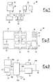
- the reference numeral (60) generally indicates the alarm system as a whole, which comprises: a power supply unit (20), which feeds the system with a direct voltage comprised within the range of from 20 to 30 volts, encased inside a modular case for flush mount in accordance with the applicable DIN provisions and connected, at the one side, with the electrical power distribution mains (10) and, at its other side, with a bifilar bus (18), through a connection line (19); sensor element (40), appended to other auxiliary electronic devices, actuator and motor units and connected with the bus (18) through connecting lines (19), which acquire and transmit data and information through digital signals of communication with a central unit (30) of the system (60); a central unit (30), connected with the bus (18) through one of said connecting lines (19) and designed to encode the sensor elements (40) assigned to the different zones and to learn said associations; devices for sound signalling (50) connected with the bus (18) through connection line (19), which start operating following commands issued by the central unit (30), in the event of an alarm.
- a power supply unit (20)
- the central unit (30), the sensor elements (40) connected with the auxiliary electronic devices, the actuator devices and the motor units, the power supply unit (20) and the sound signalling devices (50) are all provided with terminals for connection with the bifilar bus (18) through the lines (19), and with mechanical elements for fastening to frames/brackets which are used to contain electrical devices for use in civil environment, of modular type for flush mount.
- the reference numeral (21) indicates an electronic device suitable for receiving an identification code (typically, a LED diode sensible to I.R. wavelengths)
- the reference numeral (22) indicates an optical alarm display
- the reference numeral (23) indicates an optical display which displays the operating state of the system applied to the alarm system (60) (i.e., switched on/off)
- the reference numeral (24) indicates optical indicators which indicate an enabled or selected zone in learning mode
- the reference numerals (26) indicates push-buttons used to enable a zone and for selecting the zone in learning mode.
- the reference numeral (27) indicates a push-button which enables the learning mode and other auxiliary functions
- (28) indicates an optical indicator signalling that electrical power is being supplied by the electrical power distribution mains
- (29) indicates an optical indicator of sabotage alarm
- (31) is an optical indicator of technical alarm
- (32) is an optical indicator of learning mode or test mode
- (33) is an optical indicator of identification codes programming mode.
- the reference numeral (34) indicates an enabling push-button to be used for enabling the programmation of the identification codes to be sent to the several electronic devices belonging to the system (60) and configured into selected zones.
- (41) is the electronic/optoelectronic circuit of the sensor element (in particular, a movement sensor), (42) is a digital storage element (which is a programmable memory or a reading-only buffer memory), (43) is a LED diode for visual signalling the operating state of the sensor element (40), (46) is a push-button used for sending or requesting the identification codes, (47) is an electronic interface circuit connected with the bifilar bus (18) in order to transmit and/or receive digital signals.
- each sensor element (40) with a zone consists in putting the central unit (30) in a particular learning operating state during which the sound signalling devices (50) are disabled.
- the zone is selected with which the individual sensor elements (40) making a part of the system (60) must be associated, by acting on the push-buttons (26) for zone enabling selection in learning mode.
- Suitable optical indicators 22, 23, 24, 28, 29, 31, 32, 33 (typically, LED diodes) visually indicate the selection and the learning operating state of the central unit (30).
- each sensor element (40) to be associated with the zones of the system and actuates a push-button (46) mechanically sheltered inside said sensor element (40), in order to send an identification code to the central unit (30).
- the central unit (30) associates the identification code of the device with the selected zone, storing the data in a digital storage element (42) (which is either non-volatile, or buffer-fed).
- the installer repeates the above said operation for all of the devices to be associated with that particular zone and, then, selects another zone, by acting on the push-button (26) of the central unit (30); the process continues as indicated above, for all of the zone devices which the operator wishes to enable.
- the identification code sending can be triggered, following a procedure of micro electronic control unit (44) resetting, by means of a physical connection of the sensor element (40) and/or the associated electronic devices, with the bifilar bus (18) and consequent supply with power (possibly preceded by a disconnection).
- a manual pressure on push-button (46) or the connection with the bifilar bus (18) can generate on the individual device the transmission of the request for identification code to the central unit (30).
- the central unit (30) sends a specific identification code which the device stores inside its storage element (42) together with the indication of the belonging zone, or without such an indication.
- the central unit (30) can now store, if so necessary, the association procedure of the generated identification code and the selected zone; such a storage operation takes always place inside the storage element (42).
Landscapes
- Business, Economics & Management (AREA)
- Emergency Management (AREA)
- Physics & Mathematics (AREA)
- General Physics & Mathematics (AREA)
- Alarm Systems (AREA)
- Small-Scale Networks (AREA)
Claims (7)
- Système pour la réception et la gestion de signaux numériques provenant de dispositifs électroniques, du type utilisé dans des systèmes d'alarme (60) et pouvant apprendre des données de configuration de zone, comprenant :au moins une unité d'alimentation en énergie électrique (20), conçue pour une connexion avec le réseau de distribution d'énergie (10) ;une pluralité d'éléments formant capteur (40) associés à d'autres dispositifs électroniques auxiliaires et à des appareils de validation et d'invalidation et à des appareils d'actionnement et d'entraínement, chacun des éléments formant capteur (40) étant muni d'un code d'identification univoque de façon autonome ou étant configuré, de façon locale, au moyen de dispositifs prévus sur le même élément formant capteur (40) de telle façon que l'élément (40) puisse être associé à une zone du système d'alarme (60) commandée par le système de réception/gestion ;une unité de commande électronique (30) recevant des données à partir des éléments formant capteur (40) et gérant le système par assignation du code d'identification de chaque élément formant capteur (40) à la zone au moyen de commandes logicielles d'application ;une pluralité de dispositifs de transmission du son (50) commençant à fonctionner lors de l'apparition d'un événement d'alarme ;caractérisé en ce que les dispositifs de transmission du son (50) sont placés, de même, sur le même bus bifilaire (18) que les éléments formant capteur (40).l'unité d'alimentation en énergie (20), les éléments formant capteur (40) et l'unité de commande électronique (30) étant connectés par l'intermédiaire d'une pluralité de lignes de connexion (19), un bus unique bifilaire (18) sécurisant la transmission de l'énergie électrique et de données numériques entre l'unité de commande (30) et tous les éléments formant capteur (40) ;l'unité de commande électronique (30) prédisposant les éléments formant capteur (40) dans un état de sélection d'au moins une zone du système d'alarme (60) commandée par le système de réception/gestion et dans un état d'apprentissage pour apprendre l'association du code d'identification d'au moins un des éléments formant capteur (40) avec la zone sélectionnée ;
- Système pour la réception et la gestion de signaux numériques selon la revendication 1, caractérisé en ce que l'unité de commande électronique (30) est capable d'agencement, à l'avance, dans un état de sélection d'au moins une zone du système d'alarme (60) du système et dans un état de programmation tel que, suite à des signaux numériques provenant du bus bifilaire (18), l'unité de commande électronique ci-dessus (30) génère les codes d'identification conçus pour les éléments formant capteur (40) accompagnés ou non d'un signal fournissant une indication de la zone sélection.
- Système pour la réception et la gestion de signaux numériques selon la revendication 1, caractérisé en ce que l'unité de commande électronique (30) comprend au moins un dispositif formant récepteur (21), une pluralité de boutons poussoirs (26, 27) pour la sélection (26) d'au moins une zone du système d'alarme (60) et pour l'apprentissage (27) de l'association entre les codes d'identification et la zone sélectionnée, une pluralité de moyens (22, 23, 24, 28, 29, 31, 32) pour la signalisation visuelle de la sélection (24) de la zone, de l'apprentissage (32) de l'association entre les codes d'identification et la zone sélectionnée, des cas d'alarme (22, 29, 31), de la mise en service du système (23), de la présence de l'énergie électrique (28) sur le réseau de distribution d'énergie électrique (10).
- Système pour la réception et la gestion de signaux numériques selon la revendication 1, caractérisé en ce que les éléments formant capteur (40) comprennent une micro-unité de commande électronique (44) à laquelle, par l'intermédiaire d'une pluralité de lignes de connexion (19b), sont connectés un circuit optoélectronique (41), un élément de stockage non volatil ou en mémoire tampon (42), un dispositif de signalisation visuelle (43), un bouton poussoir (46) prévu pour envoyer au moins un code d'identification à l'unité de commande électronique (30), un circuit d'interface électronique (47) pour émettre et recevoir les signaux numériques sur le bus bifilaire (18), un circuit électronique (48) pour réinitialiser la micro-unité de commande électronique (44) et pour fournir de l'énergie à partir du bus bifilaire (18).
- Système pour la réception et la gestion de signaux numériques selon la revendication 1, caractérisé en ce que les éléments formant capteur (40) sont prévus pour l'envoi d'au moins un code d'identification à l'unité de commande électronique (30) après la connexion physique des éléments formant capteur (40) avec le bus bifilaire (18), les éléments formant capteur (40) comprenant une micro-unité électronique de commande (44) avec laquelle ils sont connectés, par l'intermédiaire d'une pluralité de lignes de connexion (19b), un circuit optoélectronique (41), un élément de stockage non volatil ou à mémoire tampon (42), un dispositif de signalisation visuelle (43), un circuit d'interface électronique (47) avec le bus bifilaire (18) pour l'émission et la réception de signaux numériques sur le bus bifilaire (18), un circuit électronique (48) réinitialisant la micro-unité de commande électronique (44) et pour alimenter en énergie les éléments formant capteur (40) à l'aide du bus bifilaire (18).
- Système pour la réception et la gestion de signaux numériques selon la revendication 2, caractérisé en ce que les éléments formant capteur (40) comprennent une micro-unité de commande électronique (44) avec laquelle ils sont connectés, par l'intermédiaire d'une pluralité de lignes de connexion (19b), un circuit optoélectronique (41), un dispositif de signalisation visuelle (43), un bouton poussoir (46) prévu pour envoyer des signaux numériques pour la demande d'au moins un code d'identification à l'unité de commande électronique (30), un circuit électronique (47) constituant une interface avec le bus bifilaire (18) pour émettre et recevoir les signaux numériques sur le bus bifilaire (18), un circuit électronique (48) pour réinitialiser la micro-unité de commande électronique (44) et pour alimenter en énergie à l'aide du bus bifilaire (18) un élément de stockage non volatil ou à mémoire tampon (42) pour stocker les signaux numériques qui sont accompagnés ou non d'un signal fournissant une indication de la zone sélectionnée.
- Système pour la réception et la gestion de signaux numériques selon la revendication 2, caractérisé en ce que les éléments formant capteur (40) sont prévus pour envoyer des signaux numériques pour la demande d'au moins un code d'identification à l'unité de commande électronique (30), lors d'une période de temps suivant une connexion physique des éléments formant capteur (40) avec le bus bifilaire (18), les éléments formant capteur (40) comprenant une micro-unité de commande électronique (44) avec laquelle ils sont connectés, par l'intermédiaire d'une pluralité de lignes de connexion (19b), un circuit optoélectronique (41), un dispositif de signalisation visuelle (43), un circuit électronique constituant une interface (47) avec le bus bifilaire (18) pour émettre et recevoir les signaux numériques sur le bus bifilaire (18), un circuit électronique (48) réinitialisant la micro-unité de commande électronique (44) et alimentant en énergieles élément formant capteur (40) par l'intermédiaire du bus bifilaire (18), un élément de stockage non volatil ou à mémoire tampon (42) pour stocker les signaux numériques qui sont accompagnés ou non d'un signal fournissant une indication de la zone sélectionnée.
Applications Claiming Priority (2)
| Application Number | Priority Date | Filing Date | Title |
|---|---|---|---|
| IT95MI000591A IT1277178B1 (it) | 1995-03-24 | 1995-03-24 | Sistema di ricezione e di gestione di segnali digitali provenienti da dispositivi elettronici atto all'apprendimento delle informazioni |
| ITMI950591 | 1995-03-24 |
Publications (2)
| Publication Number | Publication Date |
|---|---|
| EP0734005A1 EP0734005A1 (fr) | 1996-09-25 |
| EP0734005B1 true EP0734005B1 (fr) | 2001-10-24 |
Family
ID=11371052
Family Applications (1)
| Application Number | Title | Priority Date | Filing Date |
|---|---|---|---|
| EP96200768A Expired - Lifetime EP0734005B1 (fr) | 1995-03-24 | 1996-03-22 | Système de réception/gestion pour signaux numériques issus de dispositifs électroniques, et capables d'apprendre la configuration des capteurs, en particulier pour système d'alarme |
Country Status (4)
| Country | Link |
|---|---|
| EP (1) | EP0734005B1 (fr) |
| DE (1) | DE69616120T2 (fr) |
| ES (1) | ES2161962T3 (fr) |
| IT (1) | IT1277178B1 (fr) |
Cited By (1)
| Publication number | Priority date | Publication date | Assignee | Title |
|---|---|---|---|---|
| DE102009006610A1 (de) * | 2009-01-29 | 2010-08-05 | Wilo Se | Verfahren zur Einrichtung eines Bussystems |
Families Citing this family (4)
| Publication number | Priority date | Publication date | Assignee | Title |
|---|---|---|---|---|
| GB9624981D0 (en) * | 1996-11-30 | 1997-01-15 | Watkins Richard | Improvements relating to security systems |
| GB2330675B (en) * | 1997-10-23 | 2001-06-20 | Manhar Amlani | An addressable alarm system |
| DE19800448C2 (de) * | 1998-01-08 | 2000-04-27 | Caradon Esser Gmbh | Überwachungsanlage |
| US6693529B2 (en) * | 2000-08-16 | 2004-02-17 | Nittan Company Limited | Fire alarm system |
Family Cites Families (4)
| Publication number | Priority date | Publication date | Assignee | Title |
|---|---|---|---|---|
| DE3347357A1 (de) * | 1983-12-28 | 1985-07-11 | Siemens AG, 1000 Berlin und 8000 München | Einrichtung zum vergeben von adressen an steckbare baugruppen |
| US4933668A (en) * | 1986-09-29 | 1990-06-12 | Shepherd Intelligence Systems, Inc. | Aircraft security system |
| FR2616935B1 (fr) * | 1987-06-17 | 1991-06-21 | Duranton Rene | Dispositif d'adressage sur bus |
| DE4036639A1 (de) * | 1990-11-16 | 1992-05-21 | Esser Sicherheitstechnik | Verfahren zur ermittlung der konfiguration der melder einer gefahrenmeldeanlage und fuer die anlagenkonfigurationsbestimmung geeigneter melder |
-
1995
- 1995-03-24 IT IT95MI000591A patent/IT1277178B1/it active IP Right Grant
-
1996
- 1996-03-22 EP EP96200768A patent/EP0734005B1/fr not_active Expired - Lifetime
- 1996-03-22 ES ES96200768T patent/ES2161962T3/es not_active Expired - Lifetime
- 1996-03-22 DE DE69616120T patent/DE69616120T2/de not_active Expired - Fee Related
Cited By (1)
| Publication number | Priority date | Publication date | Assignee | Title |
|---|---|---|---|---|
| DE102009006610A1 (de) * | 2009-01-29 | 2010-08-05 | Wilo Se | Verfahren zur Einrichtung eines Bussystems |
Also Published As
| Publication number | Publication date |
|---|---|
| DE69616120D1 (de) | 2001-11-29 |
| ITMI950591A1 (it) | 1996-09-24 |
| EP0734005A1 (fr) | 1996-09-25 |
| IT1277178B1 (it) | 1997-11-05 |
| ITMI950591A0 (it) | 1995-03-24 |
| DE69616120T2 (de) | 2002-06-06 |
| ES2161962T3 (es) | 2001-12-16 |
Similar Documents
| Publication | Publication Date | Title |
|---|---|---|
| US5352957A (en) | Appliance control system with programmable receivers | |
| EP0343226B1 (fr) | Commande d'eclairage | |
| US4085403A (en) | Combined on-board remote control energy supply distribution and signaling system, particularly for automotive vehicles | |
| EP0191239B1 (fr) | Système de transmission d'information | |
| JP2968287B2 (ja) | ビル管理コントローラ | |
| EP2754165B1 (fr) | Procédé et appareil permettant d'activer/de désactiver un groupe de lampes ou d'appareils de locaux ou l'ensemble de ceux-ci | |
| CA2104797C (fr) | Appareil et systeme de surveillance | |
| EP0317852A2 (fr) | Système d'interconnexion à distance de paires de câbles | |
| US4672374A (en) | System for bilateral communication of a command station with remotely located sensors and actuators | |
| US4514729A (en) | Environmental control system and method | |
| GB2277999A (en) | Programming vehicle control units | |
| US5402101A (en) | Method for determining the configuration of detectors of a danger alarm system and for determining the system configuration of suitable detectors | |
| AU770967B2 (en) | Method of configuring elevator controls | |
| KR0176968B1 (ko) | 마스터장치와 종속장치간의 접속시스템 | |
| JP2010532603A (ja) | オープン化されたフィールドバスを介してバスネットワーク接続された機器を制御するシステム | |
| AU2005211691A1 (en) | Method of communication and home automation installation for its implementation | |
| NZ324796A (en) | Remote control of electrical apparatus via telephone network, central controller periodically polls remote locations to determine status of electrical apparatus | |
| EP0734005A1 (fr) | Système de réception/gestion pour signaux numériques issus de dispositifs électroniques, et capables d'apprendre la configuration des capteurs, en particulier pour système d'alarme | |
| US5509065A (en) | Dual span monitoring system for maintenance shelf control | |
| US20020158824A1 (en) | Device for inputting and/or outputting information | |
| CA2132663C (fr) | Clavier de saisie de donnees | |
| US6104319A (en) | Data entry keypad assembly | |
| WO2002001745A1 (fr) | Systeme de gestion de charges utilisant un signal de puissance et un signal de donnees | |
| RU2092903C1 (ru) | Система охранной сигнализации | |
| US5935222A (en) | Arrangement with a signal processing connection and a functional unit |
Legal Events
| Date | Code | Title | Description |
|---|---|---|---|
| PUAI | Public reference made under article 153(3) epc to a published international application that has entered the european phase |
Free format text: ORIGINAL CODE: 0009012 |
|
| AK | Designated contracting states |
Kind code of ref document: A1 Designated state(s): BE DE ES FR GB |
|
| 17P | Request for examination filed |
Effective date: 19970204 |
|
| 17Q | First examination report despatched |
Effective date: 20000111 |
|
| GRAG | Despatch of communication of intention to grant |
Free format text: ORIGINAL CODE: EPIDOS AGRA |
|
| GRAG | Despatch of communication of intention to grant |
Free format text: ORIGINAL CODE: EPIDOS AGRA |
|
| GRAH | Despatch of communication of intention to grant a patent |
Free format text: ORIGINAL CODE: EPIDOS IGRA |
|
| GRAH | Despatch of communication of intention to grant a patent |
Free format text: ORIGINAL CODE: EPIDOS IGRA |
|
| GRAA | (expected) grant |
Free format text: ORIGINAL CODE: 0009210 |
|
| AK | Designated contracting states |
Kind code of ref document: B1 Designated state(s): BE DE ES FR GB |
|
| REF | Corresponds to: |
Ref document number: 69616120 Country of ref document: DE Date of ref document: 20011129 |
|
| REG | Reference to a national code |
Ref country code: ES Ref legal event code: FG2A Ref document number: 2161962 Country of ref document: ES Kind code of ref document: T3 |
|
| REG | Reference to a national code |
Ref country code: GB Ref legal event code: IF02 |
|
| ET | Fr: translation filed | ||
| PLBE | No opposition filed within time limit |
Free format text: ORIGINAL CODE: 0009261 |
|
| STAA | Information on the status of an ep patent application or granted ep patent |
Free format text: STATUS: NO OPPOSITION FILED WITHIN TIME LIMIT |
|
| 26N | No opposition filed | ||
| PGFP | Annual fee paid to national office [announced via postgrant information from national office to epo] |
Ref country code: GB Payment date: 20080225 Year of fee payment: 13 |
|
| PGFP | Annual fee paid to national office [announced via postgrant information from national office to epo] |
Ref country code: DE Payment date: 20080312 Year of fee payment: 13 |
|
| GBPC | Gb: european patent ceased through non-payment of renewal fee |
Effective date: 20090322 |
|
| PG25 | Lapsed in a contracting state [announced via postgrant information from national office to epo] |
Ref country code: DE Free format text: LAPSE BECAUSE OF NON-PAYMENT OF DUE FEES Effective date: 20091001 |
|
| PG25 | Lapsed in a contracting state [announced via postgrant information from national office to epo] |
Ref country code: GB Free format text: LAPSE BECAUSE OF NON-PAYMENT OF DUE FEES Effective date: 20090322 |
|
| PGFP | Annual fee paid to national office [announced via postgrant information from national office to epo] |
Ref country code: FR Payment date: 20120410 Year of fee payment: 17 |
|
| PGFP | Annual fee paid to national office [announced via postgrant information from national office to epo] |
Ref country code: BE Payment date: 20120223 Year of fee payment: 17 |
|
| PGFP | Annual fee paid to national office [announced via postgrant information from national office to epo] |
Ref country code: ES Payment date: 20120309 Year of fee payment: 17 |
|
| BERE | Be: lapsed |
Owner name: *BTICINO S.P.A. Effective date: 20130331 |
|
| REG | Reference to a national code |
Ref country code: FR Ref legal event code: ST Effective date: 20131129 |
|
| PG25 | Lapsed in a contracting state [announced via postgrant information from national office to epo] |
Ref country code: FR Free format text: LAPSE BECAUSE OF NON-PAYMENT OF DUE FEES Effective date: 20130402 Ref country code: BE Free format text: LAPSE BECAUSE OF NON-PAYMENT OF DUE FEES Effective date: 20130331 |
|
| REG | Reference to a national code |
Ref country code: ES Ref legal event code: FD2A Effective date: 20140611 |
|
| PG25 | Lapsed in a contracting state [announced via postgrant information from national office to epo] |
Ref country code: ES Free format text: LAPSE BECAUSE OF NON-PAYMENT OF DUE FEES Effective date: 20130323 |