EP0734081A1 - Draht aus supraleitendem Oxid und Verfahren zur Herstellung - Google Patents
Draht aus supraleitendem Oxid und Verfahren zur Herstellung Download PDFInfo
- Publication number
- EP0734081A1 EP0734081A1 EP96104351A EP96104351A EP0734081A1 EP 0734081 A1 EP0734081 A1 EP 0734081A1 EP 96104351 A EP96104351 A EP 96104351A EP 96104351 A EP96104351 A EP 96104351A EP 0734081 A1 EP0734081 A1 EP 0734081A1
- Authority
- EP
- European Patent Office
- Prior art keywords
- superconducting
- substance
- silver
- exceeding
- wire
- Prior art date
- Legal status (The legal status is an assumption and is not a legal conclusion. Google has not performed a legal analysis and makes no representation as to the accuracy of the status listed.)
- Withdrawn
Links
- 238000004519 manufacturing process Methods 0.000 title claims description 23
- 239000000126 substance Substances 0.000 claims abstract description 127
- BQCADISMDOOEFD-UHFFFAOYSA-N Silver Chemical compound [Ag] BQCADISMDOOEFD-UHFFFAOYSA-N 0.000 claims abstract description 108
- 239000004332 silver Substances 0.000 claims abstract description 107
- 229910052709 silver Inorganic materials 0.000 claims abstract description 101
- 229910001316 Ag alloy Inorganic materials 0.000 claims abstract description 21
- 239000002131 composite material Substances 0.000 claims abstract description 16
- 239000000203 mixture Substances 0.000 claims abstract description 14
- 239000007769 metal material Substances 0.000 claims abstract 33
- 239000013078 crystal Substances 0.000 claims description 92
- 238000010438 heat treatment Methods 0.000 claims description 32
- 229910052761 rare earth metal Inorganic materials 0.000 claims description 4
- 239000000919 ceramic Substances 0.000 claims description 3
- 239000000463 material Substances 0.000 claims description 3
- 150000002910 rare earth metals Chemical class 0.000 claims description 3
- IJGRMHOSHXDMSA-UHFFFAOYSA-N Atomic nitrogen Chemical compound N#N IJGRMHOSHXDMSA-UHFFFAOYSA-N 0.000 description 42
- 238000005096 rolling process Methods 0.000 description 22
- 238000000034 method Methods 0.000 description 21
- 229910052757 nitrogen Inorganic materials 0.000 description 20
- 239000010949 copper Substances 0.000 description 18
- 239000007788 liquid Substances 0.000 description 15
- 238000002441 X-ray diffraction Methods 0.000 description 12
- 239000002245 particle Substances 0.000 description 11
- 238000001816 cooling Methods 0.000 description 9
- 239000002887 superconductor Substances 0.000 description 9
- QVGXLLKOCUKJST-UHFFFAOYSA-N atomic oxygen Chemical compound [O] QVGXLLKOCUKJST-UHFFFAOYSA-N 0.000 description 8
- 239000001301 oxygen Substances 0.000 description 8
- 229910052760 oxygen Inorganic materials 0.000 description 8
- 229910045601 alloy Inorganic materials 0.000 description 7
- 239000000956 alloy Substances 0.000 description 7
- 239000001307 helium Substances 0.000 description 7
- 229910052734 helium Inorganic materials 0.000 description 7
- SWQJXJOGLNCZEY-UHFFFAOYSA-N helium atom Chemical compound [He] SWQJXJOGLNCZEY-UHFFFAOYSA-N 0.000 description 7
- 239000000843 powder Substances 0.000 description 6
- 238000005491 wire drawing Methods 0.000 description 6
- 238000005481 NMR spectroscopy Methods 0.000 description 5
- 239000011159 matrix material Substances 0.000 description 5
- 238000012545 processing Methods 0.000 description 5
- 229910001020 Au alloy Inorganic materials 0.000 description 4
- 238000009413 insulation Methods 0.000 description 4
- 229910000881 Cu alloy Inorganic materials 0.000 description 3
- 229910001252 Pd alloy Inorganic materials 0.000 description 3
- 239000003507 refrigerant Substances 0.000 description 3
- 238000000137 annealing Methods 0.000 description 2
- 230000000052 comparative effect Effects 0.000 description 2
- 229910001873 dinitrogen Inorganic materials 0.000 description 2
- 238000002474 experimental method Methods 0.000 description 2
- 239000003353 gold alloy Substances 0.000 description 2
- 229910000765 intermetallic Inorganic materials 0.000 description 2
- 229910052751 metal Inorganic materials 0.000 description 2
- 239000002184 metal Substances 0.000 description 2
- 238000010791 quenching Methods 0.000 description 2
- 230000000171 quenching effect Effects 0.000 description 2
- 229910002696 Ag-Au Inorganic materials 0.000 description 1
- 229910017944 Ag—Cu Inorganic materials 0.000 description 1
- 229910000978 Pb alloy Inorganic materials 0.000 description 1
- 229910008649 Tl2O3 Inorganic materials 0.000 description 1
- PNEYBMLMFCGWSK-UHFFFAOYSA-N aluminium oxide Inorganic materials [O-2].[O-2].[O-2].[Al+3].[Al+3] PNEYBMLMFCGWSK-UHFFFAOYSA-N 0.000 description 1
- 238000004458 analytical method Methods 0.000 description 1
- 230000015572 biosynthetic process Effects 0.000 description 1
- 238000009835 boiling Methods 0.000 description 1
- 230000015556 catabolic process Effects 0.000 description 1
- 238000006243 chemical reaction Methods 0.000 description 1
- 230000003247 decreasing effect Effects 0.000 description 1
- 238000004146 energy storage Methods 0.000 description 1
- 230000005284 excitation Effects 0.000 description 1
- 125000004435 hydrogen atom Chemical group [H]* 0.000 description 1
- 238000005259 measurement Methods 0.000 description 1
- 238000012986 modification Methods 0.000 description 1
- 230000004048 modification Effects 0.000 description 1
- QTQRFJQXXUPYDI-UHFFFAOYSA-N oxo(oxothallanyloxy)thallane Chemical compound O=[Tl]O[Tl]=O QTQRFJQXXUPYDI-UHFFFAOYSA-N 0.000 description 1
- 235000012771 pancakes Nutrition 0.000 description 1
- 238000012552 review Methods 0.000 description 1
- 239000000758 substrate Substances 0.000 description 1
- 230000005469 synchrotron radiation Effects 0.000 description 1
- 238000003786 synthesis reaction Methods 0.000 description 1
Images


Classifications
-
- H—ELECTRICITY
- H10—SEMICONDUCTOR DEVICES; ELECTRIC SOLID-STATE DEVICES NOT OTHERWISE PROVIDED FOR
- H10N—ELECTRIC SOLID-STATE DEVICES NOT OTHERWISE PROVIDED FOR
- H10N60/00—Superconducting devices
- H10N60/01—Manufacture or treatment
- H10N60/0268—Manufacture or treatment of devices comprising copper oxide
- H10N60/0801—Manufacture or treatment of filaments or composite wires
Definitions
- the present invention relates to the configuration of the superconducting wire comprising the oxide superconducting substance, and its manufacturing method. More particularly, it relates to the superconducting wire which permits high-density superconductive critical current (Jc) to be applied in the magnetic field.
- Jc superconductive critical current
- oxide superconducting substances Since the first oxide superconducting substance was discovered in 1986, more than several tens of types of oxide superconducting substances have been discovered. Among them, the oxide superconducting substances which have been studied to achieve commercial use for the reason of substance stability and ease of synthesis can be narrowed down to the following four types:
- double Bi-0 layed superconducting substances are easily subjected to crystal orientation (orientation of crystal in a specific direction, providing excellent flow of superconductive current at the crystalline boundary; hence, it has a high superconductive transport current density (transport Jc) in the non-magnetic environment (Japanese Journal of Applied Physics, Vol. 30, 1991, pp. 2083 - L2084).
- transport Jc superconductive transport current density
- this substance system has a crucial problem of very small pinning force in the temperature range where cooling by liquid nitrogen is possible (Physics C, Vol 177, 1991, pp. 431 - 437). Accordingly, it is possible to manufacture the high-quality superconducting wire to be used at the temperature below 40 K, but this substance could not be used to manufacture the wire to be utilized at the temperature of 60 K and over.
- the single Tl-0 layered superconducting substances, double Tl-0 layered superconducing substances and Y based superconducting substances allow high pinning force to be exhibited up to the temperature range in the vicinity of the critical temperature (Tc).
- Tc critical temperature
- the object of the present invention is to have crystals of the oxide superconducting substance oriented in a preferred direction at a reduced cost, thereby providing the superconducting wire having a high critical current density even in the magnetic field. Furthermore, it is also the object of the present invention to provide the equipment using superconducting material such as the superconducting magnet, NMR equipment, MRI equipment, magnetic levitated train, superconducting generator, energy storage device, magnetic shield equipment, synchrotron radiation equipment and elementary particle accelerator; these devices operating in the temperature range above the temperature which allows cooling by liquid nitrogen can be manufactured by the technique provided only by the present invention.
- superconducting material such as the superconducting magnet, NMR equipment, MRI equipment, magnetic levitated train, superconducting generator, energy storage device, magnetic shield equipment, synchrotron radiation equipment and elementary particle accelerator
- the above object can be attained by thermally treating in a metallic sheath with the crystal oriented in a specific direction, the superconducting substance having a sufficiently high pinning force even in the temperature range allowing cooling by liquid nitrogen.
- the metallic sheath is preferred to be made of silver, silver alloy, or silver having ceramics dispersed therein in view of reaction characteristics with superconducting substance.
- the direction in which the silver crystal used as the metallic sheath is oriented there is fundamentally no problem regardless of which crystal surface is oriented in which direction.
- the most preferred is (1) the case where surface ⁇ 100 ⁇ of the silver crystal is parallel to the boundary between the oxide superconducting substance and metallic sheath, and direction ⁇ 001 ⁇ of the silver crystal is oriented parallel to the superconducting wire in its longitudinal direction.
- the second most preferred is (2) the case where surface ⁇ 110 ⁇ of the silver crystal is parallel to the boundary between the oxide superconducting substance and metallic sheath, and direction ⁇ 211 ⁇ of the silver crystal is oriented parallel to the superconducting wire in its longitudinal direction.
- the oxide superconducting substance is influenced by the orientation of silver crystal through heat treatment inside the metallic sheath, so that the c-axis of the crystal is perpendicular to the boundary between the oxide superconducting substance and metallic sheath, and the a-axis (it may be b-axis in the case of Y-based superconducting substance) is parallel to the superconducting wire in the longitudinal direction; such excellent orientation is obtained as a result.
- the superconducting substance is oriented in the same way though to a slightly less degree. This provides the wire having a very high Jc value.
- the drawing step and/or flattening step in the process of manufacturing the superconducting wire should be kept at the temperature of 100 to 250 degrees Celsius.
- the silver used in metallic sheath comes to have so-called cubic texture, by annealing at the temperature of not less than 400 degrees Celsius after processing at this temperature.
- the cubic texture refers to ⁇ 100 ⁇ ⁇ 001 ⁇ orientation texture, as described, for example, in Shinichi Nagashima ("Texture", pp. 133 - 185, Maruzen Co., Ltd.).
- the drawing step and/or flattening step in the process of manufacturing the superconducting wire should be kept at the temperature of 50 to 100 degrees Celsius. Then the silver used in metallic sheath comes to have the intended orientation by annealing at the temperature of at least 300 degrees Celsius after processing at this temperature.
- the powder of the superconducting substance filled in the silver tube is required to be bonded sufficiently.
- the optimum temperature for heat treatment at this time varies by dozens of degrees according to the composition of the superconducting substance and the atmosphere for heat treat (mainly partial pressure of oxygen).
- Fig. 1 illustrates the structure of the cross section of the superconducting wire used in experiment according to the present invention.
- Numeral 1 denotes the metal layer to reinforce the whole superconducting wire; it is made of silver highly reinforced by finely dispersed MgO.
- Numeral 2 shows the metal layer which bundles the superconducting filament; this is made of pure silver.
- Numeral 3 denotes the oxide superconducting substance, and 4 the pure silver.
- the total length of the wire is 50 m, and has been confirmed to be uniform in the longitudinal direction (perpendicular to the cross section). When the orientation of the silver crystal is as shown in (1) or (2), Jc exhibited a sudden decrease if the diameter of the superconducting portion exceeded 5 microns.
- Fig. 2 illustrates the cross section of the superconducting wire used in experiment according to the present invention; it has a different cross section structure.
- the flatness of the superconducting portion was varied by changing the processing conditions variously.
- the length of the brachyaxis thickness of 3
- the Jc value started to decrease.
- Jc exhibited a sudden decrease.
- the length of the brachyaxis became less than 0.5 microns, Jc decreased.
- the portion 3 is reduced too much in thickness, the wire will be broken in the longitudinal direction. If processing is possible at all, portion 3 is considered to be as thin as it could be.
- the length of the macro-axis (width of 3) was studied up to 100 microns. It was found out that there was no impact on Jc in particular. The length of the macro-axis has been found to give no impact to the orientation of the superconducting substance crystal.
- Numeral 4 shows the Ag-Au alloy, Ag-Pd alloy, Ag-Cu alloy and silver reinforced with MgO particles not exceeding 1 micron.
- the present invention have got the performance (Jc) equivalent to that of the case using the pure silver.
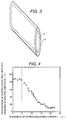
- the superconducting wire having the structure shown in Fig. 3 was manufactured in order to study the relationship between the flatness of the superconducting filament and Jc, between the thickness of the superconducting substance portion and Jc, between the orientation of silver crystal on the metallic portion of the superconducting filament and Jc, and between the orientation of the superconducting crystal and Jc.
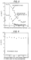
- Fig. 4 shows the relationship between the thickness of the superconducting portion (length of the brachyaxis) and the percentage of the crystals where the c-axis of the superconducting substance is perpendicular to the tape surface without exceeding 5 degrees, and the a-axis is oriented parallel in the longitudinal direction without exceeding 10 degrees.
- Fig. 5 shows the relationship between the thickness of a superconducting portion and Jc. Figs. 4 and 5 show that a high Jc value is obtained when the thickness of the superconducting portion does not exceed 5 microns.
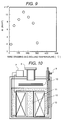
- Fig. 6 shows the Jc values varied according to the angle formed between the silver crystal and rolling direction, in other words, between the direction where the superconducting crystal is oriented and the superconducting wire. It can be seen that the Jc value is not affected by the angle formed between the direction where the superconducting crystal is oriented and the superconducting wire.
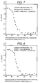
- Fig. 7 shows the relationship between the Jc values and the percentage of the silver crystal where the surface ⁇ 100 ⁇ is parallel to the tape surface and the direction ⁇ 100 ⁇ is parallel to the rolling direction.
- the critical current density in the magnetic field is substantially reduced when the percentage of the silver crystal (percentage of the cubic aggravate structure) where the surface ⁇ 100 ⁇ is parallel to the tape surface, and direction ⁇ 100 ⁇ is parallel to the rolling direction is reduced below 80 percent.
- the percentage of the silver crystal where the surface ⁇ 100 ⁇ is parallel to the tape surface and the direction ⁇ 100 ⁇ is parallel to the rolling direction must be at least 80 percent, in order to manufacture the high-quality superconducting wire.
- Fig. 8 shows the relationship between the Jc values and percentage of the crystal where the c-axis of the superconducting crystal is perpendicular to the boundary with silver without exceeding 5 degrees, and the a-axis does not exceed 10 degrees with respect to the direction ⁇ 100 ⁇ of the silver crystal forming a cubic texture.
- Figs. 7 and 8 show that the Jc value is reduced when the percentage of the silver crystal being oriented in a specific direction is below 80 percent. They also indicate that the Jc value is reduced when the percentage of the superconducting substance crystal being oriented in a specific direction is below 80 percent.
- Fig. 9 illustrates the relationship between the wire drawing and rolling temperature, and magnetic field at 77 K. It is noted that the rolling temperature is prefereable to be 50 - 250°C
- the present inventors have found out that, in the manufacture of superconducting wires, higher Jc values can be obtained when a-, b- and c-axes of the superconducting substance crystal are all oriented in the same direction (tri-axial orientation).
- the present inventors have found out a method for manufacturing the superconducting wire having a higher Jc value by tri-axial orientation of the superconducting substance.
- the structure of the silver located around the superconducting substance is oriented in a specific direction in superconducting wire according to the present invention, growth takes place while the direction of the superconducting substance crystal is being influenced by the orientation of the silver crystal at the portion where the silver and superconducting substance are in contact with each other. Accordingly, when the silver structure is oriented in a specific direction, superconducting substance is subjected to tri-axial orientation, resulting in a very high Jc value to be ensured in the superconducting wire according to the present invention.
- the inventors have manufactured superconducting substance powder.
- This powder mixture was put into an alumina-made crucible, and was baked at the temperature of 800 degrees Celsius in the flowing atmosphere of 20 percent oxygen and 80 percent nitrogen for 24 hours. This was crushed in the globe filled with 100 percent nitrogen gas. Tl 2 O 3 was added in the same molar quantity as Pb, and was mixed sufficiently.
- This powder was put into a alumina-made crucible with cover, and was calcined at the temperature of 880 degrees Celsius in the flowing atmosphere of 20 percent oxygen and 80 percent nitrogen for 24 hours.
- This powder was put into the silver pipe having a purity of 99.998% (with an inner diameter of 4 mm and outer diameter of 6 mm). This was kept at the temperature of 160 degrees Celsius, and was wire-drawn by the draw bench to get the outer diameter of 1.5 mm. Then it was rolled to a thickness of 0.07 mm with the temperature kept at 160 degrees Celsius. This was cut into tape-formed samples having a length of 5 cm. This was treated in the flowing atmosphere of 20 percent oxygen and 80 percent nitrogen.
- Fig. 3 is a schematic drawing of the superconducting wire sample.
- Numeral 5 in the drawing denotes a superconducting substance, and 6 shows the silver.
- the cross section was inspected by the light microscope and scanning electron microscope (SEM) to find out that the superconducting portion was 4 ⁇ 0.5 microns thick and 8 ⁇ 0.2 mm wide.
- the inventors studied the orientation of the silver crystal on the surface of the sample surface by X-ray diffraction after heat treatment. It was confirmed that the surface ⁇ 100 ⁇ of 90 percent crystal particle was parallel to the tape surface, and direction ⁇ 100 ⁇ was parallel to the rolling direction (i.e. parallel to the tape-formed wire in the longitudinal direction).
- the inventors removed the external silver to study the orientation of the crystal of the internal superconducting substance by X-ray diffraction. It was confirmed that the c-axis of the crystal accounting for over 85 percent of the superconducting substance was perpendicular to the tape surface without exceeding 5 degrees, and the a-axis was parallel to the longitudinal direction without exceeding 10 degrees.
- Jc superconductive critical current density
- Powdered superconducting substance manufactured according to the first embodiment was filled in the silver pipe, as in the first embodiment. This was kept at the temperature of 100 degrees Celsius, and was wire-drawn by the draw bench to get the outside diameter of 1.5 mm. After that, it was rolled to a thickness of 0.07 mm, and was cut to a length of 5 cm. This was heat-treated in the flowing atmosphere of 20 percent oxygen and 80 percent nitrogen. Temperature conditions for heat treatment the same as First Embodiment.
- the inventors studied the cross section using the light microscope and scanning electron microscope (SEM) to find out that the superconducting portion was 4 ⁇ 0.5 microns thick and 8 ⁇ 0.2 microns wide.
- the inventors studied the orientation of the silver crystal of the sample surface by X-ray diffraction after heat treatment. It was confirmed that the surface ⁇ 110 ⁇ of 90 percent crystal particle was parallel to the tape surface, and direction ⁇ 211 ⁇ was parallel to the rolling direction.
- the inventors removed the external silver to study the orientation of the crystal of the internal superconducting substance by X-ray diffraction. It was confirmed that the c-axis of the crystal accounting for over 80 percent of the superconducting substance was perpendicular to the tape surface without exceeding 5 degrees, and the a-axis was parallel to the direction ⁇ 100 ⁇ of the silver crystal, without exceeding 10 degrees.
- Jc superconductive critical current density
- Powdered superconducting substance manufactured according to the first embodiment was filled in the silver pipe, as in the first embodiment. This was put in the room having a room temperature of 20 degrees Celsius where it was annealed at 400 degrees Celsius for each wire drawing for one hour. While it was annealed, it was wire-drawn by the draw bench to get the outside diameter of 1.5 mm. After that, it was annealed at 400 degrees Celsius for one hour for each rolling. While being annealed, it was rolled to a thickness of 0.07 mm, and was cut to a length of 5 cm. This was heat-treated in the flowing atmosphere of 20 percent oxygen and 80 percent nitrogen. Temperature conditions for heat treatment the same as First Embodiment.
- the inventors studied the cross section using the light microscope and scanning electron microscope (SEM) to find out that the superconducting portion was 4 ⁇ 0.5 microns thick and 8 ⁇ 0.2 mm wide.
- the inventors studied the orientation of the silver crystal on the surface of the sample surface by X-ray diffraction after heat treatment. It was confirmed that silver crystal was oriented in random direction, without any specific crystal surface being oriented in the specific direction.
- the inventors removed the external silver to study the orientation of the crystal of the internal superconducting substance by X-ray diffraction. It was confirmed that the c-axis of the crystal accounting for over 80 percent of the superconducting substance was perpendicular to the tape surface without exceeding 5 degrees, but the a-axis was not oriented in any particular direction.
- Jc superconductive critical current density
- the orientation of the silver crystal and superconducting crystal is important to get a high Jc value.
- the inventors have manufactured powdered superconducting substance as in the first embodiment and it was filled in the similar silver pipe. This was wire-drawn at the room temperature by draw bench to get the outside diameter of 1.5 mm. After that, it was kept at 160 degrees Celsius and was rolled to various thicknesses. It was cut into tape-formed samples having a length of 5 cm, and was heat-treated as in the first embodiment.
- the inventors studied the cross section of various samples using the light microscope and scanning electron microscope (SEM) to measure the thickness of the superconducting portions.
- the inventors studied the orientation of the silver crystal of the surface of the sample by X-ray diffraction after heat treatment. It was confirmed in all samples that the surface ⁇ 100 ⁇ of 85 percent crystal particle was parallel to the tape surface, and direction ⁇ 100 ⁇ was parallel to the rolling direction (i.e. parallel to the tape-formed wire in the longitudinal direction).
- Fig. 4 shows the thickness (length of the brachyaxis) of superconducting portions and the percentage of the crystals where the a-axis of the superconducting substance is perpendicular to the tape surface without exceeding 5 degrees, and the a-axis is oriented parallel in the longitudinal direction without exceeding 10 degrees.
- Figs. 4 and 5 show that a high Jc value can be obtained when the thickness of the superconducting portion does not exceed 5 microns.
- the inventors manufactured samples in the same manner as in the second embodiment, except that the rolling direction was shifted from the longitudinal direction of the tape-formed sample in increments of 5 degrees.
- the inventors studies the orientation of the silver crystal of the surface of the sample by X-ray diffraction after heat treatment. It was confirmed in all samples that the surface ⁇ 100 ⁇ of 85 percent crystal particle was parallel to the tape surface, and direction ⁇ 211 ⁇ was parallel to the rolling direction (not matched in the longitudinal direction of the tape).
- the inventors removed the external silver to study the orientation of the crystal of the internal superconducting substance by X-ray diffraction. It was confirmed that the c-axis of the crystal accounting for over 80 percent of the superconducting substance was perpendicular to the tape surface without exceeding 5 degrees, and the a-axis is oriented parallel to direction ⁇ 100 ⁇ of the silver crystal without exceeding 10 degrees.
- Fig. 6 shows the Jc value is not affected by the angle formed between the silver crystal and rolling direction, in other words, between the direction where the superconducting crystal is oriented and the superconducting wire.
- the inventors used Ag-40% Au alloy, Ag-20% Au alloy, Ag-10% Pb alloy, Ag-10% Cu alloy, and alloy reinforced with dispersed MgO having a particle diameter of 0.1 microns which was 0.1 percent in terms of volume fraction as Ag matrix phase, and manufactured the superconducting wire samples in the same way as the first embodiment.
- the performances on the same level as those obtained in embodiment 1 (below 80 percent in Jc) were obtained in all cases.
- Fig. 7 shows the relationship between the Jc and the percentage of the silver crystal where surface ⁇ 100 ⁇ is parallel to the tape surface and direction ⁇ 100 ⁇ is parallel to the rolling direction.
- the percentage of silver crystal where surface ⁇ 100 ⁇ is parallel to the tape surface 4 and direction ⁇ 100 ⁇ is parallel to the direction of rolling is 80 percent or less, there is a substantial decrease in critical current density in the magnetic field. Accordingly, to manufacture the high-quality superconducting wire, it is necessary to ensure that the percentage of silver crystal where surface ⁇ 100 ⁇ is parallel to the tape surface and direction ⁇ 100 ⁇ is parallel to the direction of rolling (cubic texture) is over 80 percent.
- Fig. 8 shows the relationship between Jc and percentage of the crystal where the c-axis of the superconducting crystal is perpendicular to the boundary with silver without exceeding 5 degrees, and the a-axis does not exceed 10 degrees with respect to the direction ⁇ 100 ⁇ of the silver crystal forming a cubic texture.
- Figs. 7 and 8 show that the Jc value is reduced when the percentage of the silver crystal being oriented in a specific direction is below 80 percent. They also indicate that the Jc value is reduced when the percentage of the superconducting substance crystal being oriented in a specific direction is below 80 percent.
- Powdered superconducting substance manufactured in the first embodiment was filled in the silver pipe having a purity of 99.998%. This was kept at the temperature of 160 degrees Celsius, and was wire-drawn by the draw bench to get the outer diameter of 1.5 mm. Fifty five of the resulting wires were bundled and put into the silver pipe, which was again kept at the temperature of 160 degrees Celsius, and was wire-drawn by the draw bench to get the outer diameter of 1.5 mm. Fifty-five of these primary wires were bundled and were put into the silver pipe highly reinforced by finely dispersed MgO. It was again kept at 160 degrees Celsius, and was wire-drawn by the draw bench to get the outer diameter of 1.5 mm. This was cut to a length of 5 cm.
- Fig. 1 is a schematic drawing of the superconducting wire sample.
- Numeral 1 in the drawing denotes the silver highly reinforced by finely dispersed MgO.
- Numerals 2 and 4 indicate silver, and 3 the oxide superconducting substance.
- the inventors studied the cross section using a scanning electron microscope (SEM) to find out that the diameter of the superconducting portion of one filament was 4 ⁇ 0.5 microns.
- the inventors studied the orientation of the silver crystal of the filament by X-ray diffraction after heat treatment. It was confirmed that the surface ⁇ 100 ⁇ of 80 percent crystal particle was parallel to the boundary with the superconducting portion, and direction ⁇ 100 ⁇ was parallel to the wire in the longitudinal direction.
- Jc superconductive critical current density
- the wire before heat treatment, manufactured in the seventh embodiment was kept at the temperature of 160 degrees Celsius, and was rolled in the longitudinal direction. This was cut into tape-formed samples having a length of 5 cm, and was treated in the flowing atmosphere of 20 percent oxygen and 80 percent nitrogen. As conditions for heat treatment, the sample was heated from the room temperature to 800 degrees Celsius for three hours, and from 800 to 880 degrees Celsius for two hours. It was held at 880 degrees Celsius for 48 minutes and cooled down to the room temperature in ten hours.
- the inventors studied the cross section using the scanning electron microscope (SEM) to find out that the superconducting portion of one filament was 2 ⁇ 0.2 microns thick (long at the brachyaxis portion).
- the inventors studied the orientation of the silver crystal of the filament by X-ray diffraction after heat treatment. It was confirmed that the surface ⁇ 100 ⁇ of 80 percent crystal particle was parallel to the boundary with the superconducting portion, and direction ⁇ 100 ⁇ was parallel to the wire in the longitudinal direction.
- Jc superconductive critical current density
- the inventors manufactured the filament having the cross section illustrated in Fig. 2, according to the procedure of the seventh embodiment.
- the inventors studied the cross section using the scanning electron microscope (SEM) to find out that the superconducting portion of one wire was 2 ⁇ 0.2 microns thick (long at the brachyaxis portion).
- Jc superconductive critical current density
- Table 1 shows the Jc values (unit: A/cm 2 ) measured at X1, X2, X3, X4, X5, X6, n and 77 K without magnetic field being applied.
- Fig. 9 illustrates the relationship between the wire drawing and rolling temperatures and the Jc at 77 K in non-magnetic field environment. It is noted that the rolling temperature of 50 - 250°C is preferable.
- inventors manufactured the superconducting wire at the heat treatment temperature optimized in the range of 30 degrees Celsius, using YBa 2 Cu 2 O 6.9 , NdBa 2 Cu 2 O 6.9 , SmBa 2 Cu 2 O 6.9 , EuBa 2 Cu 2 O 6.9 , GdBa 2 Cu 2 O 6.9 , HoBa 2 Cu 2 O 6.9 , ErBa 2 Cu 2 O 6.9 , and YbBa 2 Cu 2 O 6.9 as superconducting substances.
- the superconductive critical current density (Jc) of the sample measured after heat treatment was as high as 100,000 A/cm 2 at 77 K at zero magnetic field, and 50,000 A/cm 2 or more when lT magnetic field was applied perpendicular to the tape.
- inventors manufactured the 100 m superconducting wire.
- the surface of this superconducting wire was coated with alumina to a thickness of about 5 microns, and was wound in pancake coils to manufacture eight superconducting coils. They were heaped in the lengthwise direction to make the superconducting magnet as shown in Fig. 10, wherein reference numeral 7 denoted power supply for excitation; 8, service port; 9, refrigerant outlet; 10, heat reflector; 11, liquid nitrogen; 12, laminated superconducting coil; and 13, cryostat.
- the coils were dipped in liquid nitrogen, to which electric current was applied thereby producing a maximum magnetic field of 3.1 Tesla.
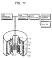
- the superconducting magnet manufactured in thirteenth embodiment was used to manufacture the NMR device configured as shown in Fig. 11, to confirm that the nuclear magnetic resonance of hydrogen atom can be measured.
- reference numeral 15 denotes cryostat; 16, normal temperature bore; 17, superconducting coil; 18, magnetic shield; 19, power lead; 20, transmitting and receiving coil; 21, room temperature shim coil; and 22, sample.
- this product allows heat insulation to be simplified; hence production cost can be cut by more than 10 percent. It is also made clear that this eliminates use of high-priced liquid helium, thereby ensuring substantial reduction in operation costs.
- the NMR device and MRI device are fundamentally based on the same operating principle. It shows that MRI device can be manufactured by using the superconducting magnet made of the superconducting wire, which is produced with the superconductor manufactured according to the present invention. According to the production costs estimated, the helium cooled refrigerator can be replaced by the less costly nitrogen refrigerator featuring a simplified structure, and simplex heat insulation can be utilized. Furthermore, the operating temperature of 77 K is much higher than the operating temperature of 4.2 K in the conventional MRI device, and specific heat of the superconducting wire is increased by about 100. Therefore, there is no possibility of quenching, hence no need of taking countermeasures for it. These considerations have made it clear that the product according to the present invention can cut down costs by at least 20 percent.
- the inventors have manufactured the magnetic shield using the superconductors according to the present invention.
- the 3-cm-thick-superconducting plate was used to make a cubic. It was cooled by 78 K nitrogen gas to form shield superconducting state, and a magnetic field of 50 gauss was applied thereto from the outside.
- the Hall sensor placed inside was used to measure the magnetic field inside. It was shown that the magnetic field was too small to be measured by the Hall sensor.
- the internal magnetic field was about 1 gauss when the external magnetic field was 3000 gausses. This has confirmed that satisfactory characteristics are provided by the magnetic shield manufactured by the superconductor according to the present invention.
- the inventors have estimated cost reduction which can be achieved by using the magnet made of the superconducting wire according to the present invention to manufacture all four-pole magnets for particle beam concentration mounted on the ring of a large sized particle accelerator, for example, an accelerator having a ring diameter of 1 km, in comparison with the case of using the conventional superconducting magnet cooled by liquid helium to make said four-pole magnets.
- the result of the study has revealed that the product according to the present invention allows the helium cooled refrigerator to be replaced by the less costly nitrogen refrigerator featuring a simplified structure. It has also been shown that the system to supply refrigerant to the superconducting magnet can be much simplified because of simple and effective heat insulation and liquid nitrogen featuring a high specific heat. Furthermore, it has been clear that the product according to the present invention can cut down costs by at least 20 percent.
- the inventors have obtained high Jc values by using, in place of silver, the silver/gold alloy, silver/palladium alloy, silver/copper alloy, alloy reinforced with MgO dispersed on the silver matrix phase, and alloy reinforced with intermetallic compound dispersed on the silver matrix phase --- all having cubic texture --- according to the procedure of the first embodiment.
- the superconductive critical current density (Jc) of all these samples measured after heat treatment was 100,000 A/cm 2 at 77 K at zero magnetic field, and over 40,000 A/cm 2 when lT magnetic field was applied perpendicular to the tape.
- the present invention provides the superconductor, superconducting wire, superconducting magnet and superconductor-based equipment which have high superconductive critical current density in a highly magnetic field and which are operated by cooling with liquid nitrogen as well as liquid helium.
- the superconductor-based equipment using the superconductor and superconducting wire according to the present invention can be driven by cooling with liquid nitrogen. Accordingly, the present invention not only replaces the superconducting portion by the conventional superconductor and superconduting wire, but when viewed as an entire system, the present invention provides a substantial simplification of the cooling system, insulation structure, countermeasures against quenching (against abrupt breakdown of the superconductor) and others.
Landscapes
- Engineering & Computer Science (AREA)
- Manufacturing & Machinery (AREA)
- Inorganic Compounds Of Heavy Metals (AREA)
- Superconductors And Manufacturing Methods Therefor (AREA)
- Compositions Of Oxide Ceramics (AREA)
Applications Claiming Priority (2)
| Application Number | Priority Date | Filing Date | Title |
|---|---|---|---|
| JP63707/95 | 1995-03-23 | ||
| JP7063707A JPH08264045A (ja) | 1995-03-23 | 1995-03-23 | 酸化物超電導線材及びその製造方法 |
Publications (1)
| Publication Number | Publication Date |
|---|---|
| EP0734081A1 true EP0734081A1 (de) | 1996-09-25 |
Family
ID=13237125
Family Applications (1)
| Application Number | Title | Priority Date | Filing Date |
|---|---|---|---|
| EP96104351A Withdrawn EP0734081A1 (de) | 1995-03-23 | 1996-03-19 | Draht aus supraleitendem Oxid und Verfahren zur Herstellung |
Country Status (2)
| Country | Link |
|---|---|
| EP (1) | EP0734081A1 (de) |
| JP (1) | JPH08264045A (de) |
Cited By (1)
| Publication number | Priority date | Publication date | Assignee | Title |
|---|---|---|---|---|
| EP1018748A4 (de) * | 1997-02-27 | 2007-04-25 | Sumitomo Electric Industries | Oxidsupraleitendes drahtmaterial |
Citations (3)
| Publication number | Priority date | Publication date | Assignee | Title |
|---|---|---|---|---|
| EP0357779A1 (de) * | 1987-12-25 | 1990-03-14 | Mitsubishi Materials Corporation | Supraleitende kabel und drähte mit hoher stromdichte und verfahren zur herstellung |
| JPH0393110A (ja) * | 1989-09-05 | 1991-04-18 | Chiyoudendou Hatsuden Kanren Kiki Zairyo Gijutsu Kenkyu Kumiai | 超電導線材 |
| EP0503525A1 (de) * | 1991-03-15 | 1992-09-16 | ABBPATENT GmbH | Verfahren zur Herstellung von supraleitenden Drähten |
-
1995
- 1995-03-23 JP JP7063707A patent/JPH08264045A/ja active Pending
-
1996
- 1996-03-19 EP EP96104351A patent/EP0734081A1/de not_active Withdrawn
Patent Citations (3)
| Publication number | Priority date | Publication date | Assignee | Title |
|---|---|---|---|---|
| EP0357779A1 (de) * | 1987-12-25 | 1990-03-14 | Mitsubishi Materials Corporation | Supraleitende kabel und drähte mit hoher stromdichte und verfahren zur herstellung |
| JPH0393110A (ja) * | 1989-09-05 | 1991-04-18 | Chiyoudendou Hatsuden Kanren Kiki Zairyo Gijutsu Kenkyu Kumiai | 超電導線材 |
| EP0503525A1 (de) * | 1991-03-15 | 1992-09-16 | ABBPATENT GmbH | Verfahren zur Herstellung von supraleitenden Drähten |
Non-Patent Citations (1)
| Title |
|---|
| PATENT ABSTRACTS OF JAPAN vol. 015, no. 273 (E - 1088) 11 July 1991 (1991-07-11) * |
Cited By (1)
| Publication number | Priority date | Publication date | Assignee | Title |
|---|---|---|---|---|
| EP1018748A4 (de) * | 1997-02-27 | 2007-04-25 | Sumitomo Electric Industries | Oxidsupraleitendes drahtmaterial |
Also Published As
| Publication number | Publication date |
|---|---|
| JPH08264045A (ja) | 1996-10-11 |
Similar Documents
| Publication | Publication Date | Title |
|---|---|---|
| EP0884787B1 (de) | Oxydsupraleitender Draht und Verfahren zu dessen Herstellung | |
| EP0356969B1 (de) | Verfahren zur Herstellung eines oxidischen Supraleiters | |
| EP1039483A1 (de) | Oxyd-supraleitender draht, spule, magnetfeldgenerator, und herstellungsverfahren für oxyd-supraleitender draht | |
| US6194985B1 (en) | Oxide-superconducting coil and a method for manufacturing the same | |
| WO2022049800A1 (en) | Structure and method for connecting superconducting layers, superconducting wire and coil including the structure | |
| EP0406862B2 (de) | Gerät für die Anwendung von Supraleitfähigkeit | |
| US20050174202A1 (en) | Superconducting wire material and method for preparation thereof, and superconducting magnet using the same | |
| EP0431643A1 (de) | Verfahren zum Herstellen eines Drahtes aus supraleitendem Oxid | |
| JP2636049B2 (ja) | 酸化物超電導体の製造方法および酸化物超電導線材の製造方法 | |
| US6316391B1 (en) | Oxide superconducting wire and method of manufacturing the same | |
| EP0385485A2 (de) | Oxidischer Supraleiter, supraleitender Draht und Spule bei Verwendung desselben und Methode zu dessen Herstellung | |
| US5110793A (en) | Ultra high energy capacitors using intense magnetic field insulation produced by high-Tc superconducting elements for electrical energy storage and pulsed power applications | |
| US5502029A (en) | Laminated super conductor oxide with strontium, calcium, copper and at least one of thallium, lead, and bismuth | |
| US5389603A (en) | Oxide superconductors, and devices and systems comprising such a superconductor | |
| US5462922A (en) | Superconductive material, a superconductive body, and a method of forming such a superconductive material or body | |
| EP0734081A1 (de) | Draht aus supraleitendem Oxid und Verfahren zur Herstellung | |
| JP4011131B2 (ja) | テープ状酸化物超電導線材ならびにそれを用いた超電導マグネットおよび電流リード | |
| JP2004327593A (ja) | 二ホウ化マグネシウム超電導線材とその製造方法 | |
| WO2013015328A1 (ja) | 超電導薄膜用基材、超電導薄膜及び超電導薄膜の製造方法 | |
| JP3873304B2 (ja) | 酸化物超電導線及びその製造方法 | |
| US5206214A (en) | Method of preparing thin film of superconductor | |
| EP0644601A2 (de) | Oxyd-Supraleiter und Verfahren zu dessen Herstellung | |
| JPH09161557A (ja) | 酸化物超電導体、酸化物超電導線材及び線材の製造方法 | |
| Silver et al. | 9 Developments in high temperature superconductivity | |
| JPH0950718A (ja) | 希土類系酸化物超電導材料およびその製造方法 |
Legal Events
| Date | Code | Title | Description |
|---|---|---|---|
| PUAI | Public reference made under article 153(3) epc to a published international application that has entered the european phase |
Free format text: ORIGINAL CODE: 0009012 |
|
| AK | Designated contracting states |
Kind code of ref document: A1 Designated state(s): CH DE LI |
|
| 17P | Request for examination filed |
Effective date: 19970321 |
|
| 17Q | First examination report despatched |
Effective date: 19980831 |
|
| STAA | Information on the status of an ep patent application or granted ep patent |
Free format text: STATUS: THE APPLICATION IS DEEMED TO BE WITHDRAWN |
|
| 18D | Application deemed to be withdrawn |
Effective date: 19990311 |