EP0734105B1 - Faseroptischer Verstärker und dispersionskompensierendes Fasermodul für faseroptischen Verstärker - Google Patents
Faseroptischer Verstärker und dispersionskompensierendes Fasermodul für faseroptischen Verstärker Download PDFInfo
- Publication number
- EP0734105B1 EP0734105B1 EP96104143A EP96104143A EP0734105B1 EP 0734105 B1 EP0734105 B1 EP 0734105B1 EP 96104143 A EP96104143 A EP 96104143A EP 96104143 A EP96104143 A EP 96104143A EP 0734105 B1 EP0734105 B1 EP 0734105B1
- Authority
- EP
- European Patent Office
- Prior art keywords
- fiber
- optical
- doped
- pump
- erbium
- Prior art date
- Legal status (The legal status is an assumption and is not a legal conclusion. Google has not performed a legal analysis and makes no representation as to the accuracy of the status listed.)
- Expired - Lifetime
Links
Images






Classifications
-
- H—ELECTRICITY
- H04—ELECTRIC COMMUNICATION TECHNIQUE
- H04B—TRANSMISSION
- H04B10/00—Transmission systems employing electromagnetic waves other than radio-waves, e.g. infrared, visible or ultraviolet light, or employing corpuscular radiation, e.g. quantum communication
- H04B10/29—Repeaters
- H04B10/291—Repeaters in which processing or amplification is carried out without conversion of the main signal from optical form
-
- H—ELECTRICITY
- H01—ELECTRIC ELEMENTS
- H01S—DEVICES USING THE PROCESS OF LIGHT AMPLIFICATION BY STIMULATED EMISSION OF RADIATION [LASER] TO AMPLIFY OR GENERATE LIGHT; DEVICES USING STIMULATED EMISSION OF ELECTROMAGNETIC RADIATION IN WAVE RANGES OTHER THAN OPTICAL
- H01S3/00—Lasers, i.e. devices using stimulated emission of electromagnetic radiation in the infrared, visible or ultraviolet wave range
- H01S3/05—Construction or shape of optical resonators; Accommodation of active medium therein; Shape of active medium
- H01S3/06—Construction or shape of active medium
- H01S3/063—Waveguide lasers, i.e. whereby the dimensions of the waveguide are of the order of the light wavelength
- H01S3/067—Fibre lasers
- H01S3/06708—Constructional details of the fibre, e.g. compositions, cross-section, shape or tapering
- H01S3/06725—Fibre characterized by a specific dispersion, e.g. for pulse shaping in soliton lasers or for dispersion compensating [DCF]
-
- H—ELECTRICITY
- H01—ELECTRIC ELEMENTS
- H01S—DEVICES USING THE PROCESS OF LIGHT AMPLIFICATION BY STIMULATED EMISSION OF RADIATION [LASER] TO AMPLIFY OR GENERATE LIGHT; DEVICES USING STIMULATED EMISSION OF ELECTROMAGNETIC RADIATION IN WAVE RANGES OTHER THAN OPTICAL
- H01S3/00—Lasers, i.e. devices using stimulated emission of electromagnetic radiation in the infrared, visible or ultraviolet wave range
- H01S3/05—Construction or shape of optical resonators; Accommodation of active medium therein; Shape of active medium
- H01S3/06—Construction or shape of active medium
- H01S3/063—Waveguide lasers, i.e. whereby the dimensions of the waveguide are of the order of the light wavelength
- H01S3/067—Fibre lasers
- H01S3/06754—Fibre amplifiers
-
- H—ELECTRICITY
- H01—ELECTRIC ELEMENTS
- H01S—DEVICES USING THE PROCESS OF LIGHT AMPLIFICATION BY STIMULATED EMISSION OF RADIATION [LASER] TO AMPLIFY OR GENERATE LIGHT; DEVICES USING STIMULATED EMISSION OF ELECTROMAGNETIC RADIATION IN WAVE RANGES OTHER THAN OPTICAL
- H01S3/00—Lasers, i.e. devices using stimulated emission of electromagnetic radiation in the infrared, visible or ultraviolet wave range
- H01S3/05—Construction or shape of optical resonators; Accommodation of active medium therein; Shape of active medium
- H01S3/06—Construction or shape of active medium
- H01S3/063—Waveguide lasers, i.e. whereby the dimensions of the waveguide are of the order of the light wavelength
- H01S3/067—Fibre lasers
- H01S3/06754—Fibre amplifiers
- H01S3/06758—Tandem amplifiers
-
- H—ELECTRICITY
- H01—ELECTRIC ELEMENTS
- H01S—DEVICES USING THE PROCESS OF LIGHT AMPLIFICATION BY STIMULATED EMISSION OF RADIATION [LASER] TO AMPLIFY OR GENERATE LIGHT; DEVICES USING STIMULATED EMISSION OF ELECTROMAGNETIC RADIATION IN WAVE RANGES OTHER THAN OPTICAL
- H01S3/00—Lasers, i.e. devices using stimulated emission of electromagnetic radiation in the infrared, visible or ultraviolet wave range
- H01S3/09—Processes or apparatus for excitation, e.g. pumping
- H01S3/091—Processes or apparatus for excitation, e.g. pumping using optical pumping
- H01S3/094—Processes or apparatus for excitation, e.g. pumping using optical pumping by coherent light
- H01S3/094003—Processes or apparatus for excitation, e.g. pumping using optical pumping by coherent light the pumped medium being a fibre
-
- H—ELECTRICITY
- H01—ELECTRIC ELEMENTS
- H01S—DEVICES USING THE PROCESS OF LIGHT AMPLIFICATION BY STIMULATED EMISSION OF RADIATION [LASER] TO AMPLIFY OR GENERATE LIGHT; DEVICES USING STIMULATED EMISSION OF ELECTROMAGNETIC RADIATION IN WAVE RANGES OTHER THAN OPTICAL
- H01S3/00—Lasers, i.e. devices using stimulated emission of electromagnetic radiation in the infrared, visible or ultraviolet wave range
- H01S3/09—Processes or apparatus for excitation, e.g. pumping
- H01S3/091—Processes or apparatus for excitation, e.g. pumping using optical pumping
- H01S3/094—Processes or apparatus for excitation, e.g. pumping using optical pumping by coherent light
- H01S3/094061—Shared pump, i.e. pump light of a single pump source is used to pump plural gain media in parallel
-
- H—ELECTRICITY
- H01—ELECTRIC ELEMENTS
- H01S—DEVICES USING THE PROCESS OF LIGHT AMPLIFICATION BY STIMULATED EMISSION OF RADIATION [LASER] TO AMPLIFY OR GENERATE LIGHT; DEVICES USING STIMULATED EMISSION OF ELECTROMAGNETIC RADIATION IN WAVE RANGES OTHER THAN OPTICAL
- H01S3/00—Lasers, i.e. devices using stimulated emission of electromagnetic radiation in the infrared, visible or ultraviolet wave range
- H01S3/09—Processes or apparatus for excitation, e.g. pumping
- H01S3/091—Processes or apparatus for excitation, e.g. pumping using optical pumping
- H01S3/094—Processes or apparatus for excitation, e.g. pumping using optical pumping by coherent light
- H01S3/0941—Processes or apparatus for excitation, e.g. pumping using optical pumping by coherent light of a laser diode
-
- H—ELECTRICITY
- H01—ELECTRIC ELEMENTS
- H01S—DEVICES USING THE PROCESS OF LIGHT AMPLIFICATION BY STIMULATED EMISSION OF RADIATION [LASER] TO AMPLIFY OR GENERATE LIGHT; DEVICES USING STIMULATED EMISSION OF ELECTROMAGNETIC RADIATION IN WAVE RANGES OTHER THAN OPTICAL
- H01S3/00—Lasers, i.e. devices using stimulated emission of electromagnetic radiation in the infrared, visible or ultraviolet wave range
- H01S3/30—Lasers, i.e. devices using stimulated emission of electromagnetic radiation in the infrared, visible or ultraviolet wave range using scattering effects, e.g. stimulated Brillouin or Raman effects
- H01S3/302—Lasers, i.e. devices using stimulated emission of electromagnetic radiation in the infrared, visible or ultraviolet wave range using scattering effects, e.g. stimulated Brillouin or Raman effects in an optical fibre
-
- H—ELECTRICITY
- H04—ELECTRIC COMMUNICATION TECHNIQUE
- H04B—TRANSMISSION
- H04B10/00—Transmission systems employing electromagnetic waves other than radio-waves, e.g. infrared, visible or ultraviolet light, or employing corpuscular radiation, e.g. quantum communication
- H04B10/25—Arrangements specific to fibre transmission
- H04B10/2507—Arrangements specific to fibre transmission for the reduction or elimination of distortion or dispersion
- H04B10/2513—Arrangements specific to fibre transmission for the reduction or elimination of distortion or dispersion due to chromatic dispersion
- H04B10/2525—Arrangements specific to fibre transmission for the reduction or elimination of distortion or dispersion due to chromatic dispersion using dispersion-compensating fibres
-
- H—ELECTRICITY
- H04—ELECTRIC COMMUNICATION TECHNIQUE
- H04B—TRANSMISSION
- H04B10/00—Transmission systems employing electromagnetic waves other than radio-waves, e.g. infrared, visible or ultraviolet light, or employing corpuscular radiation, e.g. quantum communication
- H04B10/29—Repeaters
- H04B10/291—Repeaters in which processing or amplification is carried out without conversion of the main signal from optical form
- H04B10/2912—Repeaters in which processing or amplification is carried out without conversion of the main signal from optical form characterised by the medium used for amplification or processing
- H04B10/2916—Repeaters in which processing or amplification is carried out without conversion of the main signal from optical form characterised by the medium used for amplification or processing using Raman or Brillouin amplifiers
-
- H—ELECTRICITY
- H04—ELECTRIC COMMUNICATION TECHNIQUE
- H04B—TRANSMISSION
- H04B10/00—Transmission systems employing electromagnetic waves other than radio-waves, e.g. infrared, visible or ultraviolet light, or employing corpuscular radiation, e.g. quantum communication
- H04B10/29—Repeaters
- H04B10/291—Repeaters in which processing or amplification is carried out without conversion of the main signal from optical form
- H04B10/293—Signal power control
- H04B10/294—Signal power control in a multiwavelength system, e.g. gain equalisation
-
- H—ELECTRICITY
- H01—ELECTRIC ELEMENTS
- H01S—DEVICES USING THE PROCESS OF LIGHT AMPLIFICATION BY STIMULATED EMISSION OF RADIATION [LASER] TO AMPLIFY OR GENERATE LIGHT; DEVICES USING STIMULATED EMISSION OF ELECTROMAGNETIC RADIATION IN WAVE RANGES OTHER THAN OPTICAL
- H01S2301/00—Functional characteristics
- H01S2301/04—Gain spectral shaping, flattening
-
- H—ELECTRICITY
- H01—ELECTRIC ELEMENTS
- H01S—DEVICES USING THE PROCESS OF LIGHT AMPLIFICATION BY STIMULATED EMISSION OF RADIATION [LASER] TO AMPLIFY OR GENERATE LIGHT; DEVICES USING STIMULATED EMISSION OF ELECTROMAGNETIC RADIATION IN WAVE RANGES OTHER THAN OPTICAL
- H01S3/00—Lasers, i.e. devices using stimulated emission of electromagnetic radiation in the infrared, visible or ultraviolet wave range
- H01S3/005—Optical devices external to the laser cavity, specially adapted for lasers, e.g. for homogenisation of the beam or for manipulating laser pulses, e.g. pulse shaping
- H01S3/0064—Anti-reflection devices, e.g. optical isolaters
-
- H—ELECTRICITY
- H01—ELECTRIC ELEMENTS
- H01S—DEVICES USING THE PROCESS OF LIGHT AMPLIFICATION BY STIMULATED EMISSION OF RADIATION [LASER] TO AMPLIFY OR GENERATE LIGHT; DEVICES USING STIMULATED EMISSION OF ELECTROMAGNETIC RADIATION IN WAVE RANGES OTHER THAN OPTICAL
- H01S3/00—Lasers, i.e. devices using stimulated emission of electromagnetic radiation in the infrared, visible or ultraviolet wave range
- H01S3/005—Optical devices external to the laser cavity, specially adapted for lasers, e.g. for homogenisation of the beam or for manipulating laser pulses, e.g. pulse shaping
- H01S3/0078—Frequency filtering
-
- H—ELECTRICITY
- H01—ELECTRIC ELEMENTS
- H01S—DEVICES USING THE PROCESS OF LIGHT AMPLIFICATION BY STIMULATED EMISSION OF RADIATION [LASER] TO AMPLIFY OR GENERATE LIGHT; DEVICES USING STIMULATED EMISSION OF ELECTROMAGNETIC RADIATION IN WAVE RANGES OTHER THAN OPTICAL
- H01S3/00—Lasers, i.e. devices using stimulated emission of electromagnetic radiation in the infrared, visible or ultraviolet wave range
- H01S3/05—Construction or shape of optical resonators; Accommodation of active medium therein; Shape of active medium
- H01S3/06—Construction or shape of active medium
- H01S3/063—Waveguide lasers, i.e. whereby the dimensions of the waveguide are of the order of the light wavelength
- H01S3/067—Fibre lasers
- H01S3/06708—Constructional details of the fibre, e.g. compositions, cross-section, shape or tapering
- H01S3/06712—Polarising fibre; Polariser
-
- H—ELECTRICITY
- H01—ELECTRIC ELEMENTS
- H01S—DEVICES USING THE PROCESS OF LIGHT AMPLIFICATION BY STIMULATED EMISSION OF RADIATION [LASER] TO AMPLIFY OR GENERATE LIGHT; DEVICES USING STIMULATED EMISSION OF ELECTROMAGNETIC RADIATION IN WAVE RANGES OTHER THAN OPTICAL
- H01S3/00—Lasers, i.e. devices using stimulated emission of electromagnetic radiation in the infrared, visible or ultraviolet wave range
- H01S3/09—Processes or apparatus for excitation, e.g. pumping
- H01S3/091—Processes or apparatus for excitation, e.g. pumping using optical pumping
- H01S3/094—Processes or apparatus for excitation, e.g. pumping using optical pumping by coherent light
- H01S3/094003—Processes or apparatus for excitation, e.g. pumping using optical pumping by coherent light the pumped medium being a fibre
- H01S3/094011—Processes or apparatus for excitation, e.g. pumping using optical pumping by coherent light the pumped medium being a fibre with bidirectional pumping, i.e. with injection of the pump light from both two ends of the fibre
-
- H—ELECTRICITY
- H01—ELECTRIC ELEMENTS
- H01S—DEVICES USING THE PROCESS OF LIGHT AMPLIFICATION BY STIMULATED EMISSION OF RADIATION [LASER] TO AMPLIFY OR GENERATE LIGHT; DEVICES USING STIMULATED EMISSION OF ELECTROMAGNETIC RADIATION IN WAVE RANGES OTHER THAN OPTICAL
- H01S3/00—Lasers, i.e. devices using stimulated emission of electromagnetic radiation in the infrared, visible or ultraviolet wave range
- H01S3/09—Processes or apparatus for excitation, e.g. pumping
- H01S3/091—Processes or apparatus for excitation, e.g. pumping using optical pumping
- H01S3/094—Processes or apparatus for excitation, e.g. pumping using optical pumping by coherent light
- H01S3/094003—Processes or apparatus for excitation, e.g. pumping using optical pumping by coherent light the pumped medium being a fibre
- H01S3/094015—Processes or apparatus for excitation, e.g. pumping using optical pumping by coherent light the pumped medium being a fibre with pump light recycling, i.e. with reinjection of the unused pump light back into the fiber, e.g. by reflectors or circulators
-
- H—ELECTRICITY
- H01—ELECTRIC ELEMENTS
- H01S—DEVICES USING THE PROCESS OF LIGHT AMPLIFICATION BY STIMULATED EMISSION OF RADIATION [LASER] TO AMPLIFY OR GENERATE LIGHT; DEVICES USING STIMULATED EMISSION OF ELECTROMAGNETIC RADIATION IN WAVE RANGES OTHER THAN OPTICAL
- H01S3/00—Lasers, i.e. devices using stimulated emission of electromagnetic radiation in the infrared, visible or ultraviolet wave range
- H01S3/09—Processes or apparatus for excitation, e.g. pumping
- H01S3/091—Processes or apparatus for excitation, e.g. pumping using optical pumping
- H01S3/094—Processes or apparatus for excitation, e.g. pumping using optical pumping by coherent light
- H01S3/094076—Pulsed or modulated pumping
-
- H—ELECTRICITY
- H01—ELECTRIC ELEMENTS
- H01S—DEVICES USING THE PROCESS OF LIGHT AMPLIFICATION BY STIMULATED EMISSION OF RADIATION [LASER] TO AMPLIFY OR GENERATE LIGHT; DEVICES USING STIMULATED EMISSION OF ELECTROMAGNETIC RADIATION IN WAVE RANGES OTHER THAN OPTICAL
- H01S3/00—Lasers, i.e. devices using stimulated emission of electromagnetic radiation in the infrared, visible or ultraviolet wave range
- H01S3/09—Processes or apparatus for excitation, e.g. pumping
- H01S3/091—Processes or apparatus for excitation, e.g. pumping using optical pumping
- H01S3/094—Processes or apparatus for excitation, e.g. pumping using optical pumping by coherent light
- H01S3/09408—Pump redundancy
-
- H—ELECTRICITY
- H01—ELECTRIC ELEMENTS
- H01S—DEVICES USING THE PROCESS OF LIGHT AMPLIFICATION BY STIMULATED EMISSION OF RADIATION [LASER] TO AMPLIFY OR GENERATE LIGHT; DEVICES USING STIMULATED EMISSION OF ELECTROMAGNETIC RADIATION IN WAVE RANGES OTHER THAN OPTICAL
- H01S3/00—Lasers, i.e. devices using stimulated emission of electromagnetic radiation in the infrared, visible or ultraviolet wave range
- H01S3/09—Processes or apparatus for excitation, e.g. pumping
- H01S3/091—Processes or apparatus for excitation, e.g. pumping using optical pumping
- H01S3/094—Processes or apparatus for excitation, e.g. pumping using optical pumping by coherent light
- H01S3/094096—Multi-wavelength pumping
-
- H—ELECTRICITY
- H01—ELECTRIC ELEMENTS
- H01S—DEVICES USING THE PROCESS OF LIGHT AMPLIFICATION BY STIMULATED EMISSION OF RADIATION [LASER] TO AMPLIFY OR GENERATE LIGHT; DEVICES USING STIMULATED EMISSION OF ELECTROMAGNETIC RADIATION IN WAVE RANGES OTHER THAN OPTICAL
- H01S3/00—Lasers, i.e. devices using stimulated emission of electromagnetic radiation in the infrared, visible or ultraviolet wave range
- H01S3/09—Processes or apparatus for excitation, e.g. pumping
- H01S3/091—Processes or apparatus for excitation, e.g. pumping using optical pumping
- H01S3/094—Processes or apparatus for excitation, e.g. pumping using optical pumping by coherent light
- H01S3/0941—Processes or apparatus for excitation, e.g. pumping using optical pumping by coherent light of a laser diode
- H01S3/09415—Processes or apparatus for excitation, e.g. pumping using optical pumping by coherent light of a laser diode the pumping beam being parallel to the lasing mode of the pumped medium, e.g. end-pumping
-
- H—ELECTRICITY
- H01—ELECTRIC ELEMENTS
- H01S—DEVICES USING THE PROCESS OF LIGHT AMPLIFICATION BY STIMULATED EMISSION OF RADIATION [LASER] TO AMPLIFY OR GENERATE LIGHT; DEVICES USING STIMULATED EMISSION OF ELECTROMAGNETIC RADIATION IN WAVE RANGES OTHER THAN OPTICAL
- H01S3/00—Lasers, i.e. devices using stimulated emission of electromagnetic radiation in the infrared, visible or ultraviolet wave range
- H01S3/10—Controlling the intensity, frequency, phase, polarisation or direction of the emitted radiation, e.g. switching, gating, modulating or demodulating
- H01S3/13—Stabilisation of laser output parameters, e.g. frequency or amplitude
- H01S3/1301—Stabilisation of laser output parameters, e.g. frequency or amplitude in optical amplifiers
- H01S3/13013—Stabilisation of laser output parameters, e.g. frequency or amplitude in optical amplifiers by controlling the optical pumping
-
- H—ELECTRICITY
- H01—ELECTRIC ELEMENTS
- H01S—DEVICES USING THE PROCESS OF LIGHT AMPLIFICATION BY STIMULATED EMISSION OF RADIATION [LASER] TO AMPLIFY OR GENERATE LIGHT; DEVICES USING STIMULATED EMISSION OF ELECTROMAGNETIC RADIATION IN WAVE RANGES OTHER THAN OPTICAL
- H01S3/00—Lasers, i.e. devices using stimulated emission of electromagnetic radiation in the infrared, visible or ultraviolet wave range
- H01S3/14—Lasers, i.e. devices using stimulated emission of electromagnetic radiation in the infrared, visible or ultraviolet wave range characterised by the material used as the active medium
- H01S3/16—Solid materials
- H01S3/1601—Solid materials characterised by an active (lasing) ion
- H01S3/1603—Solid materials characterised by an active (lasing) ion rare earth
- H01S3/1608—Solid materials characterised by an active (lasing) ion rare earth erbium
-
- H—ELECTRICITY
- H04—ELECTRIC COMMUNICATION TECHNIQUE
- H04B—TRANSMISSION
- H04B2210/00—Indexing scheme relating to optical transmission systems
- H04B2210/003—Devices including multiple stages, e.g., multi-stage optical amplifiers or dispersion compensators
-
- H—ELECTRICITY
- H04—ELECTRIC COMMUNICATION TECHNIQUE
- H04B—TRANSMISSION
- H04B2210/00—Indexing scheme relating to optical transmission systems
- H04B2210/25—Distortion or dispersion compensation
- H04B2210/256—Distortion or dispersion compensation at the repeater, i.e. repeater compensation
Definitions
- This invention relates to an apparatus optically connected to an optical fiber transmission line and to a method of processing an optical signal.
- This invention relates to an optical fiber amplifier and a dispersion compensating fiber module for use with an optical fiber amplifier.
- the length of the doped fiber is set to a value at which a maximum gain is obtained in order to assure a high conversion efficiency from pump power to signal power.
- the rare earth doped fiber (which will be hereinafter discussed in connection with a representative EDF) must operate in a condition wherein the degree of the saturation of the gain is low.
- the concentration of high level ions is represented by N2 while the concentration of all ions is represented by N1 and N2/N1 is defined as pump ratio
- the length of the doped fiber in order to raise the average pump ratio N2/N1 of the doped fiber over the entire length, the length of the doped fiber must be set short.
- a wavelength multiplexing optical amplifier cannot be used in a condition in which it exhibits a high efficiency of conversion from pump power to signal power. This is because, since the rare earth doped fiber is intentionally formed short so as to prevent saturation in order to obtain a gain over a wide bandwidth or to make the gain flat, pump power which has not been converted into a signal will leak out from the other end of the doped fiber.
- the rare earth doped fiber must be used in a condition wherein the pump power leaks out therefrom.
- the pump light is returned not only to the doped fiber but also to the pump source.
- This pump light may possibly give rise to unstable operation of the pump source such as interference.
- the transmission system has subjects to be solved in terms of the dispersion compensation, reduction in nonlinear effects (effects having a bad influence on the transmission quality) in an optical fiber serving as a transmission line and economic wide bandwidth wavelength multiplexing transmission.
- an optical fiber serving as a transmission line has a dispersion characteristic and accumulates a dispersion amount in proportion to the length thereof.
- the dispersion amount is reset at the regenerative repeaters. Consequently, the accumulation of the dispersion amount does not make a problem.
- the signal wavelength used for transmission should be set to a zero dispersion wavelength.
- DCF dispersion compensating fiber
- DCF Dispersion Compensating Fiber
- a wavelength dispersion in wavelength multiplexing transmission, a wavelength dispersion must be compensated for, and since the compensation for a wavelength dispersion is expected to be most likely put into practical use where a dispersion compensating fiber is employed, it is prospective to use a dispersion compensating fiber. Further, it is investigated to incorporate a dispersion compensating fiber as a part into an optical amplifier repeater. Generally, however, the mode field diameter of a dispersion compensating fiber (DCF) is set small in order to compensate for a dispersion, and consequently, nonlinear effects are liable to occur and, as the dispersion amount to be compensated for increases, also the loss increases.
- DCF dispersion compensating fiber
- the loss must be compensated for so that a transmission optical signal may not be influenced by nonlinear effects which degrade the quality of a signal such as self-phase modulation (SPM) and cross-phase modulation (XPM) occurring in the dispersion compensating fiber.
- SPM self-phase modulation
- XPM cross-phase modulation
- the possible method has a problem in that designing of a level diagram is difficult.
- a flat and wide optical amplification bandwidth is required for an optical amplifier for WDM, also a rare earth doped fiber optical amplifier has a wavelength dependency of the gain. Accordingly, there is a subject to be solved in that it is difficult to realize a flat and wide amplification bandwidth.
- a rare earth doped fiber optical amplifier having a high gain sometimes suffers from unnecessary oscillations which are produced when it performs optical amplification. If such unnecessary oscillations are produced, the rare earth doped fiber optical amplifier operates but unstably.
- spontaneous emission light (ASE) of 1.53 to 1.57 ⁇ m in wavelength is generated when optical amplification is performed, and since the ASE is repetitively reflected from reflection points in the erbium-doped-fiber optical amplifier, unnecessary oscillations are liable to be produced.
- an erbium-doped-fiber optical amplifier adjusted for multiple wavelength collection amplification that is, an erbium-doped-fiber optical amplifier having a high pump rate
- unnecessary oscillations are liable to be produced at this wavelength.
- the erbium-doped-fiber optical amplifier operates but unstably.
- DSF dispersion-shifted, single-mode optical fiber
- the pre- and a post-amplifier stages are coupled to the compensation stage by means of a wavelength multiplexer and are pumped by a pair of semiconductor pump lasers.
- EP-A-0 566 236 discloses an optical amplifier for amplifying signals of different wavelengths throughout a spetral window so as to modify the amplification of each signal such that the output levels of the signals are more equal than the input levels when the input levels differ by more than a predetermined amount.
- EP-A-0 458 256 discloses an optical fiber telecommunication line comprising active-fiber optical amplifiers in which the reflectivity towards the amplifier's active fiber is limited below a critical value lower by at least 10 dB than the reflectivity due to the Rayleigh scattering within the line fibers.
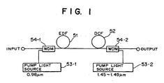
- FIGS. 1 to 5 Several aspects of the present invention will first be described with reference to FIGS. 1 to 5.
- the optical fiber amplifier shown includes a rare earth doped fiber 51 and a dispersion compensating fiber 52 disposed at two front and rear stages.
- the optical fiber amplifier further includes a first pump source 53-1 for producing pump light of a first wavelength band for the rare earth doped fiber 51, and a first optical coupler 54-1 for introducing the pump light from the first pump source 53-1 into the rare earth doped fiber 51.
- the optical fiber amplifier further includes a second pump source 53-2 for producing pump light of a second wavelength band for the dispersion compensating fiber 52, and a second optical coupler 54-2 for introducing the pump light from the second pump source 53-2 into the dispersion compensating fiber 52.
- the dispersion compensating fiber 52 is pumped with pump light of the second wavelength band from the second pump source 53-2 to cause Raman amplification to occur.
- a rare earth doped fiber optical amplification element formed from the rare earth doped fiber 51 and a Raman optical amplification element formed from the dispersion compensating fiber 52 which is pumped with pump light to cause Raman amplification to occur are connected in cascade connection at two front and rear stages.
- the wavelength band of the pump light produced by the first pump source 53-1 is a 0.98 ⁇ m band while the wavelength band of the pump light produced by the second pump source 53-2 is a 1.47 ⁇ m band (1.45 to 1.49 ⁇ m: in the following description, unless otherwise specified, the terminology "1.47 ⁇ m band” signifies a band from 1.45 to 1.49 ⁇ m).
- the Raman optical amplification element may be disposed as a front stage amplification element while the rare earth doped fiber'optical amplification element is disposed as a rear stage amplification element. Or, where the rare earth doped fiber optical amplification element is formed as an optical amplification element having a low noise figure, the rare earth doped fiber optical amplification element may be disposed as a front stage amplification element while the Raman optical amplification element is disposed as a rear stage amplification element.
- the second pump source 53-2 may include a pair of pump sources and a polarizing multiplexer for orthogonally polarizing and multiplexing pump light from the pump sources or may include a combination of a pump source and a depolarizer by which pump light is depolarized or else may produce modulated pump light.
- pump light (whose wavelength band is, for example, 0.98 ⁇ m) from the first pump source 53-1 is introduced into the rare earth doped fiber 51 by way of the first optical coupler 54-1 while pump light (whose wavelength band is, for example, 1.47 ⁇ m) from the second pump source 53-2 is introduced into the dispersion compensating fiber 52 by way of the second optical coupler 54-2. Consequently, the dispersion compensating fiber 52 can be pumped with the pump light of the second wavelength band from the second pump source 53-2 to cause Raman amplification to occur.
- the second pump source 53-2 includes the pair of pump sources and the polarizing multiplexer, it supplies pump light obtained by orthogonal polarization and multiplexing of the pump light from the pump sources. Meanwhile, where the second pump source 53-2 includes the combination of the pump source and the depolarizer, it supplies depolarized pump light. On the other hand, where the second pump source 53-2 produces modulated pump light, it supplies the modulated pump light.
- the optical fiber amplifier of the first aspect of the present invention since a rare earth doped fiber optical amplification element formed from the rare earth doped fiber 51 and a Raman optical amplification element formed from the dispersion compensating fiber 52 which is pumped with pump light to cause Raman amplification to occur are connected in cascade connection, there is an advantage in that the optical fiber amplifier of the two stage construction makes use of the pump power with a high efficiency.
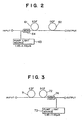
- FIG. 2 there is shown in block diagram an optical fiber amplifier according to a second aspect of the present invention.
- the optical fiber amplifier shown includes an erbium-doped-fiber 61 and a dispersion compensating fiber 62 disposed at two front and rear stages.
- the optical fiber amplifier further includes a pump source 63 for producing pump light of the 1.47 ⁇ m band, and an optical coupler 64 for introducing the pump light from the pump source 63 into the erbium-doped-fiber 61.
- the dispersion compensating fiber 62 is pumped with residual pump light from the erbium-doped-fiber 61 to cause Raman amplification to occur.
- a rare earth doped fiber optical amplification element formed from the erbium-doped-fiber 61 which is a rare earth doped fiber and a Raman optical amplification element (which is formed from the dispersion compensating fiber 62) which is pumped with pump light, which is capable of pumping the rare earth doped fiber optical amplification element, to cause Raman amplification to occur are connected in cascade connection, and the pump source 63 for supplying pump light for pumping the rare earth doped fiber optical amplification element and the Raman optical amplification element is provided.
- the pump source 63 may include a pair of pump sources and a polarizing multiplexer for orthogonally polarizing and multiplexing pump light from the pump sources or may include a combination of a pump source and a depolarizer by which pump light is depolarized or else may produce modulated pump light.
- the erbium-doped-fiber 61 is pumped with pump light of the 1.47 ⁇ m band whereas the dispersion compensating fiber 62 is pumped with residual pump light from the erbium-doped-fiber 61 to cause Raman amplification to occur.
- the pump source 63 includes the pair of pump sources and the polarizing multiplexer, it supplies pump light obtained by orthogonal polarization and multiplexing of the pump light from the pump sources. Meanwhile, where the pump source 63 includes the combination of the pump source and the depolarizer, it supplies depolarized pump light. On the other hand, where the pump source 63 produces modulated pump light, it supplies the modulated pump light.
- the optical fiber amplifier of the second aspect of the present invention since the common pump source for supplying pump light for pumping the rare earth doped fiber optical amplification element and the Raman optical amplification element is provided, the optical fiber amplifier can make use of the pump power with a high efficiency, and the number of pump sources to be used can be reduced, which contributes to simplification in construction and reduction in cost.
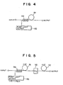
- FIG. 3 there is shown in block diagram an optical fiber amplifier according to a third aspect of the present invention.
- the optical fiber amplifier shown includes an erbium-doped-fiber 71 and a dispersion compensating fiber 72 disposed at two front and rear stages.
- the optical fiber amplifier further includes a pump source 73 for producing pump light of the 1.47 ⁇ m band, and an optical coupler 74 for introducing the pump light from the pump source 73 into the dispersion compensating fiber 72.
- the erbium-doped-fiber 71 is pumped with residual pump light from the dispersion compensating fiber 72.
- the dispersion compensating fiber 72 is caused to perform Raman amplification using pump light of the 1.47 ⁇ m band whereas the erbium-doped-fiber 71 is pumped with residual pump light from the dispersion compensating fiber 72.
- the optical fiber amplifier of the seventh aspect of the present invention since the common pump source for supplying pump light for pumping the erbium-doped-fiber 71 and the dispersion compensating fiber 72 is provided, the optical fiber amplifier can make use of the pump power with a high efficiency, and the number of pump sources to be used can be reduced, which contributes to simplification in construction and reduction in cost.
- the optical fiber amplifier shown includes a dispersion compensating fiber (rare earth doped dispersion compensating fiber) 81 doped with a rare earth element, a pump source 82 for producing pump light for the rare earth doped dispersion compensating fiber 81, and an optical coupler 83 for introducing the pump light from the pump source 82 into the rare earth doped dispersion compensating fiber 81.
- a dispersion compensating fiber rare earth doped dispersion compensating fiber
- a pump source 82 for producing pump light for the rare earth doped dispersion compensating fiber 81
- an optical coupler 83 for introducing the pump light from the pump source 82 into the rare earth doped dispersion compensating fiber 81.
- pump light from the pump source 82 is introduced into the the rare earth doped dispersion compensating fiber 81 doped with a rare earth element to pump the rare earth doped dispersion compensating fiber 81.
- the optical fiber amplifier of the fourth aspect of the present invention since the dispersion compensating fiber is doped with a rare earth element, the loss of the dispersion compensating fiber is reduced while dispersion compensation is performed. Further, the optical fiber amplifier with a dispersion compensating function can optically amplify signal light sufficiently.
- FIG. 5 there is shown in block diagram an optical fiber amplifier according to a fifth aspect of the present invention.
- the optical fiber amplifier shown includes an erbium-doped-fiber 91 and a dispersion compensating fiber 92 disposed at two front and rear stages.
- the optical fiber amplifier further includes a pump source 93 for producing pump light of the 1.47 ⁇ m band for the erbium-doped-fiber 91, and an optical coupler 94 for introducing the pump light from the pump source 93 into the erbium-doped-fiber 91.
- the optical fiber amplifier further includes an optical filter 95 interposed between the erbium-doped-fiber 91 and the dispersion compensating fiber 92 for intercepting residual pump light of the 1.47 ⁇ m band coming out from the erbium-doped-fiber 91.
- the erbium-doped-fiber 91 is pumped with pump light of the 1.47 ⁇ m band from the pump source 93.
- residual pump light of the 1.47 ⁇ m band coming out from the erbium-doped-fiber 91 is intercepted by the optical filter 95 so that it is prevented from being inputted to the dispersion compensating fiber 92.
- the optical fiber amplifier of the fifth aspect of the present invention since the optical filter 95 which prevents pump light of the 1.47 ⁇ m band from being inputted to the dispersion compensating fiber 92 is provided, leaking pump power of the 1.47 ⁇ m band causes the dispersion compensating fiber 92 to perform Raman amplification, and consequently, the optical fiber amplifier can be prevented from unstable operation or from variation of the wavelength dependency of the amplification band.
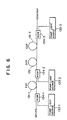
- FIG. 6 there is shown in block diagram an optical fiber amplifier according to a sixth aspect of the present invention.
- the optical fiber amplifier shown includes a first erbium-doped-fiber (EDF) 131-1 having a low noise figure, a dispersion compensating fiber (DCF) 132 and a second erbium-doped-fiber (EDF) 131-2.
- the first erbium-doped-fiber 131-1, the dispersion compensating fiber 132 and the second erbium-doped-fiber 131-2 are provided at a front stage, a middle stage and a rear stage, respectively.
- the optical fiber amplifier further includes a first erbium-doped-fiber pump source 133-1 for producing pump light of a wavelength band for the first erbium-doped-fiber 131-1, and an optical coupler 134-1 for introducing the pump light from the first erbium-doped-fiber pump source 133-1 into the first erbium-doped-fiber 131-1.
- the optical fiber amplifier further includes a dispersion compensating fiber pump source 133-2 for producing pump light of a wavelength band for the dispersion compensating fiber 132, and another optical coupler 134-2 for introducing the pump light from the dispersion compensating fiber pump source 133-2 into the dispersion compensating fiber 132.
- the optical fiber amplifier further includes a second erbium-doped-fiber pump source 133-3 for producing pump light of a wavelength band for the second erbium-doped-fiber 131-2, and a further optical coupler 134-3 for introducing the pump light from the second erbium-doped-fiber pump source 133-3 into the second erbium-doped-fiber 131-2.
- the dispersion compensating fiber 132 is pumped with the pump light from the dispersion compensating fiber pump source 133-2 to cause Raman amplification to occur.
- a rare earth doped fiber optical amplification element formed from the erbium-doped-fiber 131-1 which is a rare earth doped fiber and having a low noise figure is disposed as a front stage amplification element; a Raman optical amplification element formed from the dispersion compensating fiber 132 for causing Raman amplification to occur when pumped with pump light is disposed as a middle stage amplification element; and another rare earth doped fiber optical amplification element formed from the erbium-doped-fiber 131-2 which is a rare earth doped fiber is disposed as a rear stage amplification element.
- pump light from the first erbium-doped-fiber pump source 133-1 is introduced into the first erbium-doped-fiber 131-1 by way of the optical coupler 134-1 and pump light from the dispersion compensating fiber pump source 133-2 is introduced into the dispersion compensating fiber 132 by way of the optical coupler 134-2 while pump light from the second erbium-doped-fiber pump source 133-3 is introduced into the second erbium-doped-fiber 131-2 by way of the optical coupler 134-3.
- the dispersion compensating fiber 132 can be pumped with the pump light of the wavelength band therefor from the dispersion compensating fiber pump source 133-2 to cause Raman amplification to occur.
- the dispersion compensating fiber 132 and the second erbium-doped-fiber 131-2 are provided at the front stage, the middle stage and the rear stage, respectively, such that residual pump light from the first and second erbium-doped-fibers 131-1 and 131-2 positioned on the front and the rear to the dispersion compensating fiber 132 are used for Raman amplification of the dispersion compensating fiber 132, the dispersion compensating fiber 132 exhibits an improved compensation effect. Consequently, a wide bandwidth optical amplifier can be realized while achieving simplification in structure and reduction in cost.
- the optical fiber amplifier shown includes a dispersion compensating fiber (DCF) 141, a pump source 142 for producing pump light, and an optical coupler 143 for introducing pump light from the pump source 142 into the dispersion compensating fiber 141.
- the dispersion compensating fiber 141 is pumped with pump light from the pump source 142 to cause Raman amplification to occur.
- the optical fiber amplifier includes a dispersion compensating fiber module which includes the dispersion compensating fiber 141, and the pump source 142 for pumping the dispersion compensating fiber 141 to cause Raman amplification to occur.
- the optical fiber amplifier may further include, an optical circulator through which input signal light is inputted to the optical fiber amplifier and through which output signal light of the optical fiber amplifier is outputted, or may additionally include an isolator provided at an input port of the optical fiber amplifier to which input signal light is inputted and/or another isolator provided at an output port of the optical fiber amplifier from which output signal light is outputted.
- the dispersion compensating fiber 141 is pumped with pump light from the pump source 142 to cause Raman amplification to occur.
- optical fiber amplifier includes the additional optical circulator
- input signal light is inputted to the optical fiber amplifier and output signal light of the optical fiber amplifier is outputted both through the optical circulator.
- the optical fiber amplifier includes the additional isolators
- input signal light is inputted through one of the isolators whereas output signal light is outputted through the other isolator.
- the optical fiber amplifier of the seventh aspect of the present invention since it is constructed using the module wherein the dispersion compensating fiber 141 is pumped to cause Raman amplification to occur, there is an advantage in that the loss of the dispersion compensating fiber 141 can be reduced.
- the additional circulators are provided at the input and output portions of the optical fiber amplifier, the number of isolators to be used can be reduced, which contributes to reduction in cost.
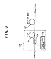
- the optical fiber amplifier shown includes a rare earth doped fiber optical amplification element 154 formed from a rare earth doped fiber 61, and an optical fiber attenuation element 155 formed from an optical fiber or an optical fiber with an optical isolator.
- the optical fiber attenuation element 155 suppresses unstable operation of the rare earth doped fiber optical amplification element 154.
- the optical fiber attenuation element 155 may serve also as a Raman optical amplification element which is pumped with pump light to cause Raman amplification to occur.
- reference numeral 63 denotes a pump source
- 64 an optical coupler which introduces pump light from the pump source 63 into the rare earth doped fiber 61.
- the optical fiber attenuation element 155 suppresses the unstable operation of the rare earth doped fiber optical amplification element 154.
- the optical fiber attenuation element 155 may be pumped with residual pump light from the erbium-doped-fiber 61 to cause Raman amplification to occur.
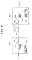
- the optical fiber amplifier shown includes a front stage optical amplification element 156-1 and a rear stage optical amplification element 156-2 each formed as a rare earth doped fiber optical amplification element formed from a rare earth doped fiber 121-1 or 121-2.
- the front stage optical amplification element 156-1 and the rear stage optical amplification element 156-2 form an optical amplification unit.
- the optical fiber amplifier further includes an optical fiber attenuation element 157 formed from an optical fiber or an optical fiber with an optical isolator interposed between the front stage optical amplification element 156-1 and the rear stage optical amplification element 156-2 of the optical amplification unit.
- the optical fiber attenuation element 157 suppresses unstable operation of the optical amplification unit.
- the optical fiber attenuation element 157 may serve also as a Raman optical amplification element which is pumped with pump light to cause Raman amplification to occur.
- reference numerals 123-1 and 123-3 denote each a pump source
- reference numeral 124-1 denotes an optical coupler for introducing pump light from the pump source 123-1 into the rare earth doped fiber 121-1
- 124-3 an optical coupler for introducing pump light from the pump source 123-3 into the rare earth doped fiber 121-2.
- the optical fiber attenuation element 157 suppresses the unstable operation of the front stage optical amplification element 156-1 and the rear stage optical amplification element 156-2 in the optical amplification unit.
- the optical fiber attenuation element 157 may be pumped with residual pump light from the erbium-doped-fibers 121-1 and 121-2 to cause Raman amplification to occur.
- optical fiber attenuation element 157 is interposed between the front stage optical amplification element 156-1 and the rear stage optical amplification element 156-2 in the optical amplification unit, unstable operation of the front stage optical amplification element 156-1 and the rear stage optical amplification element 156-2 in the optical amplification unit can be suppressed to achieve stabilized optical amplification of the optical fiber amplifier.
- FIG. 10 is a block diagram showing a first preferred embodiment of the present invention.
- the optical fiber amplifier shown in FIG. 10 includes an isolator 144, a dispersion compensating fiber 141 and a optical demultiplexer-multiplexer 143 disposed in this order from the input side.
- a pump source 142 is connected to the optical demultiplexer-multiplexer 143.
- the pump source 142 is formed from a pump source which produces pump light of a band (for example, from 1.44 to 1.49 ⁇ m) in which band compensation for erbium-doped-fiber amplification by Raman amplification can be performed. Pump light from the pump source 142 is introduced into an output end of the dispersion compensating fiber 141 by way of the optical demultiplexer-multiplexer 143.
- the optical fiber amplifier includes a dispersion compensating fiber module which includes the dispersion compensating fiber 141 and the pump source 142.
- the dispersion compensating fiber 141 can be pumped with pump light from the pump source 142 to cause Raman amplification to occur.
- the mode field diameter of the dispersion compensating fiber 141 is generally small, the threshold level of the Raman amplification is low, and consequently, Raman amplification occurs readily.
- the dispersion compensating fiber has the following characteristic.
- the dispersion compensating fiber is so small in diameter that the mode field diameter thereof is approximately one half that of an ordinary fiber and provides nonlinear effects (stimulated Raman scattering (SRS), stimulated Brillouin scattering (SBS), four wave mixing (FWM), self phase modulation effect (SPM) and so forth) more likely than a fiber which is used as a transmission line.
- SRS stimulated Raman scattering
- SBS stimulated Brillouin scattering
- FWM four wave mixing
- SPM self phase modulation effect
- the dispersion compensating fiber is, in its form of use, not so long as a fiber which is used as a transmission line, it is known that it can be used if the optical power of light to pass it is set low. This is because also the influence of nonlinear effects increases as the length increases.
- the input power is restricted to a low value as described hereinabove, which makes it difficult to design the level as an optical amplifier.
- the Raman amplification may possibly be very useful in the following point.
- the dispersion compensating fiber performs Raman amplification, then the dispersion compensating fiber itself acts as an optical amplifier and can compensate for the loss.
- the Raman amplification signifies that, making use of stimulated Raman scattering, that is, a phenomenon that, when intense monochromatic light is irradiated upon an optical fiber, it coacts with optical phonons of the optical fiber so that coherent Stokes light displaced by an intrinsic amount in wavelength is generated by stimulated emission, the wavelength of the monochromatic light is set so that the Stokes light may have an equal wavelength to that of the signal light thereby to amplify the signal light by stimulated emission.
- stimulated Raman scattering that is, a phenomenon that, when intense monochromatic light is irradiated upon an optical fiber, it coacts with optical phonons of the optical fiber so that coherent Stokes light displaced by an intrinsic amount in wavelength is generated by stimulated emission, the wavelength of the monochromatic light is set so that the Stokes light may have an equal wavelength to that of the signal light thereby to amplify the signal light by stimulated emission.
- the dispersion compensating fiber 141 by pumping the dispersion compensating fiber 141 with pump light of the band described above from the pump source 142 to cause Raman amplification to occur as described above, compensation for the loss of the dispersion compensating fiber (including levelling of a concave in gain of an erbium-doped fiber and complementary compensation for a decrease in gain of an erbium-doped-fiber) can be achieved by the Raman amplification.
- the erbium-doped-fiber is pumped with pump light of the wavelength equal to or less than 1.44 ⁇ m to cause Raman amplification to occur.
- another isolator 144-2 may be additionally provided on the output side.
- optical fiber amplifier of the present embodiment may be modified otherwise such that, in place of the provision of an isolator at the input portion or at both of the input and output portions of the optical fiber amplifier, input signal light is inputted by way of an optical circulator and output signal light is outputted by way of an optical circulator
- FIG. 12 is a block diagram showing a second preferred embodiment of the present invention.
- the optical fiber amplifier shown includes an isolator 55-1, an optical demultiplexer-multiplexer 54-1, an erbium-doped-fiber (rare earth doped fiber) 51, another isolator 55-2, a dispersion compensating fiber 52, another optical demultiplexer-multiplexer 54-2 and a further isolator 55-3 disposed in this order from the input side.
- a pump source 53-1 is connected to the optical demultiplexer-multiplexer 54-1 while another pump source 53-2 is connected to the optical demultiplexer-multiplexer 54-2.
- the pump source 53-1 produces pump light of a first wavelength band for the erbium-doped-fiber 51 (for example, the 0.98 ⁇ m band), and the pump source 53-2 produces pump light of a second wavelength band for the dispersion compensating fiber 52 (for example, the 1.47 ⁇ m band (1.45 to 1.49 ⁇ m) or the band up to 1.44 ⁇ m (equal to or less than 1.44 ⁇ m).
- a first wavelength band for the erbium-doped-fiber 51 for example, the 0.98 ⁇ m band
- the pump source 53-2 produces pump light of a second wavelength band for the dispersion compensating fiber 52 (for example, the 1.47 ⁇ m band (1.45 to 1.49 ⁇ m) or the band up to 1.44 ⁇ m (equal to or less than 1.44 ⁇ m).
- the dispersion compensating fiber 52 can be pumped with pump light from the pump source 53-2 to cause Raman amplification to occur in accordance with the same principle as that of the embodiment described hereinabove. Accordingly, also in the present embodiment, by pumping the dispersion compensating fiber 52 with pump light of the 1.47 ⁇ m band or the band up to 1.44 ⁇ m from the pump source 53-2 to cause Raman amplification to occur, compensation for the loss of the dispersion compensating fiber can be achieved by the Raman amplification.
- the wavelength characteristic of the gain of a rare earth doped fiber optical amplifier depends upon rare earth ions
- the wavelength characteristic of the gain of a Raman optical amplifier depends upon the pump wavelength and the peak value thereof is shifted if the pump wavelength is changed. Accordingly, the pump wavelength when Raman amplification is performed can be selected so that the wavelength characteristic of the gain of the rare earth doped fiber optical amplifier may be compensated for. This allows realization of an optical amplifier of a wide bandwidth.
- the Raman amplification involves an amplification band, and if the wavelength dependency of the gain by the Raman amplification is utilized, not only mere compensation for the loss of a dispersion compensating fiber can be achieved, but also the amplification bandwidth of an erbium-doped-fiber can be complemented to increase the bandwidth.
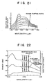
- the wavelength characteristic of an erbium-doped-fiber amplifier is not flat as seen in FIG. 21 or 22, by causing Raman amplification to occur using a dispersion compensating fiber, the unevenness of the wavelength characteristic of the erbium-doped-fiber amplifier can be leveled. As a result, a wide bandwidth optical amplifier can be realized, which is suitably used for multiple wavelength collective amplification (refer to FIG. 22) or the like.
- the rare earth doped fiber optical amplification element formed from an erbium-doped-fiber which is a rare earth doped fiber may be constructed as an optical amplification element having a low noise index.
- the optical fiber amplifier shown in FIG. 12 is constructed such that the rare earth doped fiber optical amplification element formed from an erbium-doped-fiber is disposed as a front stage amplification element while the Raman optical amplification element formed from a dispersion compensating fiber is disposed as a rear stage amplification element
- the construction of the optical fiber amplifier is not limited to the specific one described above and may be constructed otherwise such that a Raman optical amplification element formed from a dispersion compensating fiber or a silica-type-optical-fiber is disposed as a front stage amplification element while a rare earth doped fiber optical amplification element formed from an erbium-doped-fiber is disposed as a rear stage amplification element (where such Raman optical amplification element is formed from a silica-type-optical-fiber, a single pump source can be used commonly as a pump source for the silica-type-optical-fiber and another pump source for the erbium-doped
- the pump source 53-2 may be formed, for example, from a pair of pump sources and a polarizing multiplexer for orthogonally polarizing and multiplexing pump light from the pump sources similarly to pump sources 53-2, 53-2' and 53-2" shown in FIGS. 18-20.
- the pump source 53-2 may otherwise be formed from a combination of a pump source and a depolarizer by which pump light is depolarized or else may be formed so as to generate modulated pump light.
- pump sources 53-2, 53-2' and 53-2" shown in FIGS. 18-20 will be hereinafter described in connection with a sixth embodiment of the present invention and first and second modifications to the sixth embodiment, respectively.
- FIG. 13 is a block diagram showing a third preferred embodiment of the present invention.
- the optical fiber amplifier shown includes an isolator 65-1, an optical demultiplexer-multiplexer 64, an erbium-doped-fiber (rare earth doped fiber) 61, another isolator 65-2, a dispersion compensating fiber 62, and a further isolator 65-3 disposed in this order from the input side.
- a pump source 63 is connected to the optical demultiplexer-multiplexer 64.
- the pump source 63 produces pump light, for example, of the 1.47 ⁇ m band (1.45 to 1.49 ⁇ m).
- pump light is introduced into one end of the erbium-doped-fiber 61 from the optical demultiplexer-multiplexer 64 to pump the erbium-doped-fiber 61 to amplify signal light. Consequently, residual pump light arrives at the other end of the erbium-doped-fiber 61. Thereafter, the residual pump light is supplied by way of the isolator 65-2 to the dispersion compensating fiber 62 so that Raman amplification may occur in the dispersion compensating fiber 62.
- the reason why signal light can be amplified by both of the erbium-doped-fiber and the dispersion compensating fiber using the common pump source to them is such as follows.
- the pump wavelength band when signal Light of the 1.55 ⁇ m band is Raman amplified is the 1.47 ⁇ m band (1.45 to 1.49 ⁇ m) which is the pump wavelength band of the erbium-doped-fiber (EDF), and accordingly, Raman amplification can be caused to occur using residual pump power when the EDF is pumped with light of the 1.47 band. From this reason, while optical amplification is performed by the erbium-doped-fiber 61, the loss of the dispersion compensating fiber 62 can be compensated for.
- a wide bandwidth optical amplifier wherein the unevenness of the wavelength characteristic of the erbium-doped-fiber amplifier is leveled can be realized, and the wide bandwidth optical amplifier can be suitably applied to multiple wavelength collective amplification. Further, since the single pump source is involved, the optical fiber amplifier can be constructed in simplified structure and at a reduced cost.
- optical fiber amplifier of the present embodiment may be modified such that, in place of the provision of an isolator at the input portion or at both of the input and output portions of the optical fiber amplifier, input signal light is inputted by way of an optical circulator and output signal light is outputted by way of the optical circulator.
- the pump source 63 may alternatively be formed from two pump sources and a polarizing multiplexer which orthogonally polarizes and multiplexes pump light from the pump sources or may otherwise be formed from a combination of a pump source and a depolarizer by means of which pump light is depolarized or else may generate modulated pump light.
- FIG. 14 is a block diagram showing a first modification to the third embodiment of the present invention.
- the optical fiber amplifier shown includes an isolator 65-1, an optical demultiplexer-multiplexer 64-1, an erbium-doped-fiber (rare earth doped fiber) 61-1, another isolator 65-2, a dispersion compensating fiber 62, another erbium-doped-fiber (rare earth doped fiber) 61-2, another optical demultiplexer-multiplexer 64-2 and a further isolator 65-3 disposed in this order from the input side.
- a pump source 63-1 is connected to the optical demultiplexer-multiplexer 64-1, and another pump source 63-2 is connected to the optical demultiplexer-multiplexer 64-2.
- the pump source 63-1 and 63-2 both produce pump light of, for example, the 1.47 ⁇ m band (1.45 to 1.49 ⁇ m).
- pump light from the pump source 63-1 is introduced into an input end of the erbium-doped-fiber 61-1 from the optical demultiplexer-multiplexer 64-1 to pump the erbium-doped-fiber 61-1 to amplify signal light. Consequently, residual pump light arrives at the other end of the erbium-doped-fiber 61-1. Thereafter, the residual pump light is supplied by way of the isolator 65-2 to the dispersion compensating fiber 62 so that Raman amplification may occur in the dispersion compensating fiber 62.
- pump light from the pump source 63-2 is introduced into an output end of the erbium-doped-fiber 61-2 by way of the optical demultiplexer-multiplexer 64-2 to pump the erbium-doped-fiber 61-2 to amplify the signal light. Also in this instance, residual pump light arrives at an input end of the erbium-doped-fiber 61-2. Further, also the residual pump light is supplied to the dispersion compensating fiber 62 so that Raman amplification may occur in the dispersion compensating fiber 62.
- the dispersion compensating fiber 62 causes Raman amplification to occur using the residual pump light from the erbium-doped-fibers 61-1 and 61-2 on the front and rear sides, the dispersion compensating fiber 62 exhibits a higher compensation effect as much. Consequently, a wide bandwidth optical amplifier can be realized while achieving simplification in structure and reduction in cost.
- the present modified optical fiber amplifier may be further modified such that, in place of the provision of an isolator at the input portion or at both of the input and output portions, input signal light is inputted by way of an optical circulator and output signal light is outputted by way of the optical circulator in a similar manner as in the arrangement shown in FIG. 18 or 30.
- a pump source and an optical demultiplexer-multiplexer for the dispersion compensating fiber 62 may be provided additionally.
- an optical fiber amplifier may be constructed using pump sources 133-1 to 133-3 of the 0.98 ⁇ m band and optical demultiplexer-multiplexers 134-1 to 134-3.
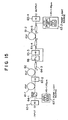
- FIG. 15 is a block diagram showing a second modification to the third embodiment of the present invention.
- the optical fiber amplifier shown includes an isolator 65-1, an optical demultiplexer-multiplexer 64-1, an erbium-doped-fiber 61-1, another isolator 65-2, a dispersion compensating fiber 62, another optical demultiplexer-multiplexer 64-3, an optical filter 66, a further isolator 65-3, a further optical demultiplexer-multiplexer 64-4, another erbium-doped-fiber 61-2, a still further optical demultiplexer-multiplexer 64-5, and a still further isolator 65-4 disposed in this order from the input side.
- a pump source 63-1 is connected to the optical demultiplexer-multiplexer 64-1
- another pump source 63-2 is connected to the optical demultiplexer-multiplexer 64-5.
- the pump sources 63-1 and 63-2 both produce pump light, for example, of the 1.47 ⁇ m band (1.45 to 1.49 ⁇ m).
- An optical signal line including the optical filter 66 and the isolator 65-3 and a pump light line are disposed in parallel between the optical demultiplexer-multiplexers 64-3 and 64-4.
- pump light from the pump source 63-1 is introduced into an input end of the erbium-doped-fiber 61-1 by way of the optical demultiplexer-multiplexer 64-1 to pump the erbium-doped-fiber 61-1 to amplify signal light.
- residual pump light arrives at the other end of the erbium-doped-fiber 61-1.
- the residual pump light is supplied to the dispersion compensating fiber 62 by way of the isolator 65-2 to cause Raman amplification to occur.
- pump light from the pump source 63-2 is introduced into an output end of the erbium-doped-fiber 61-2 by way of the optical demultiplexer-multiplexer 64-5 to pump the erbium-doped-fiber 61-2 to amplify the signal light.
- residual pump light arrives at the input end of the erbium-doped-fiber 61-2.
- the residual pump light is supplied by way of the optical demultiplexer-multiplexers 64-4 and 64-3 to the dispersion compensating fiber 62 to cause Raman amplification to occur.
- the dispersion compensating fiber 62 since the dispersion compensating fiber 62 causes Raman amplification to occur using the residual pump light from the erbium-doped-fibers 61-1 and 61-2 at the front and the rear to the dispersion compensating fiber 62, the dispersion compensating fiber 62 exhibits a higher compensation effect as much. Thus, a wide bandwidth optical amplifier can be realized while achieving simplification in structure and reduction in cost.
- the present modified optical fiber amplifier may be modified such that, in place of the provision of an isolator at the input portion or at both of the input and output portions, input signal light is inputted by way of an optical circulator and output signal light is outputted by way of an optical circulator.
- a pump source and an optical demultiplexer-multiplexer for the dispersion compensating fiber 62 may be provided additionally.
- an optical fiber amplifier may be constructed using pump sources 133-1 to 133-3 of the 0.98 ⁇ m band and optical demultiplexer-multiplexers 134-1 to 134-3.
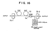
- FIG. 16 is a block diagram showing a fourth preferred embodiment of the present invention.
- the optical fiber amplifier shown includes an isolator 75-1, an erbium-doped-fiber (rare earth doped fiber) 71, a dispersion compensating fiber 72, an optical demultiplexer-multiplexer 74, and another isolator 75-2 disposed in this order from the input side.
- a pump source 73 is connected to the optical demultiplexer-multiplexer 74.
- the pump source 73 produces pump light, for example, of the 1.47 ⁇ m band (1.45 to 1.49 ⁇ m).
- pump light is introduced into an output side of the dispersion compensating fiber 72 by way of the optical demultiplexer-multiplexer 74 to cause Raman amplification to occur. Then, residual pump light from the dispersion compensating fiber 72 is introduced into an output end of the erbium-doped-fiber 71 to pump the erbium-doped-fiber 71 to amplify signal light.
- the unevenness of the wavelength characteristic of the erbium-doped-fiber can be leveled to realize a wide bandwidth optical amplifier similarly as in the seventh embodiment described above.
- the wide bandwidth optical amplifier can be applied suitably to multiple wavelength collective amplification. Further, since the only single pump source is required, the optical fiber amplifier of the present embodiment is simplified in structure and reduced in cost.
- optical fiber amplifier of the present embodiment may be modified such that, in place of the provision of an isolator at the input portion or at both of the input and output portions, input signal light is inputted by way of an optical circulator and output signal light is outputted by way of the optical circulator.
- the pump source 73 may be formed from a pair of pump sources, and a polarizing multiplexer for orthogonally polarizing and multiplexing pump light from the pump sources or may be formed from a combination of a pump source and a depolarizer by which pump light is depolarized or else may generate modulated pump light.
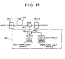
- FIG. 17 is a block diagram showing a fifth preferred embodiment of the present invention.
- the optical fiber amplifier shown includes an isolator 144-1, a dispersion compensating fiber 141, a polarization keeping optical demultiplexer-multiplexer 143 and another isolator 144-2 disposed in this order from the input side.
- a polarization keeping pump source 142 is connected to the optical demultiplexer-multiplexer 143.
- the pump source 142 is formed from a pair of pump sources 142A and 142B, and a polarizing multiplexer (PBS) 142C for orthogonally polarizing and multiplexing pump light from the pump sources 142A and 142B.
- PBS polarizing multiplexer
- the pump sources 142A and 142B have an equal pump power and output pump light of, for example, 1.45 to 1.49 ⁇ m (or 1.45 to 1.48 ⁇ m).
- an optical demultiplexer-multiplexer of the optical film type is used for the optical demultiplexer-multiplexer 143 so that multiplexing or demultiplexing of light may be performed while maintaining polarization conditions of the light.
- orthogonally polarized multiplexed pump light is introduced into an output end of the dispersion compensating fiber 141 by way of the optical demultiplexer-multiplexer 143 so that Raman amplification may occur effectively in the dispersion compensating fiber 141.
- Raman amplification may occur effectively in the dispersion compensating fiber 141.
- optical fiber amplifier of the present embodiment may be modified such that, in place of the provision of an isolator at the input portion or at both of the input and output portions, input signal light is inputted by way of an optical circulator and output signal light is outputted by way of the optical circulator.
- the pump source 142 may be constructed, for example, from a combination of a pump source and a depolarizer so that pump light may be depolarized similarly to the pump source 53-2' or 53-2" shown in FIG. 44 or 45 or may generate modulated pump light.
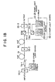
- FIG. 18 is a block diagram showing a sixth preferred embodiment of the present invention.
- the optical fiber amplifier shown includes an isolator 55-1, an optical demultiplexer-multiplexer 54-1, an erbium-doped-fiber (rare earth doped fiber) 51, another isolator 55-2, a dispersion compensating fiber 52, a polarization keeping optical demultiplexer-multiplexer 54-2 and a further isolator 55-3 disposed in this order from the input side.
- a pump source 53-1 is connected to the optical demultiplexer-multiplexer 54-1 while a pump source 53-2 of the polarization multiplexing type is connected to the optical demultiplexer-multiplexer 54-2.
- the pump source 53-1 outputs pump light of, for example, the 0.98 ⁇ m band.
- the pump source 53-2 is formed from a pair of pump sources 53-2A and 53-2B, and a polarizing multiplexer (PBS) 53-2C for orthogonally polarizing and multiplexing pump light from the pump sources 53-2A and 53-2B.
- PBS polarizing multiplexer
- the pump sources 53-2A and 53-2B have an equal pump power and both output pump light of, for example, 1.45 to 1.49 ⁇ m (or 1.45 to 1.48 ⁇ m).
- optical demultiplexer-multiplexer of the fusion type which has no polarization keeping function is used for the optical demultiplexer-multiplexer 54-1 while another optical demultiplexer-multiplexer of the optical film type is used for the optical demultiplexer-multiplexer 54-2 so that multiplexing or demultiplexing of light may be performed while keeping polarization conditions of the light.
- pump light from the pump source 53-1 is inputted to one end of the erbium-doped-fiber 51 from the optical demultiplexer-multiplexer 54-1 together with signal light. Consequently, the signal light is amplified in the erbium-doped-fiber 51.
- orthogonally polarized multiplexed pump light is introduced into an output end of the dispersion compensating fiber 52 by way of the optical demultiplexer-multiplexer 54-2 to cause Raman amplification to occur effectively in the dispersion compensating fiber 52.
- the loss of the dispersion compensating fiber 52 is compensated for by such Raman amplification.
- optical fiber amplifier of the present embodiment may be modified such that, in place of the provision of an isolator at the input portion or at both of the input and output portions, input signal light is inputted by way of an optical circulator and output signal light is outputted by way of the optical circulator.
- the rare earth doped fiber optical amplification element formed from an erbium-doped-fiber may be formed as an optical amplification element which has a low noise figure.
- a Raman optical amplification element formed from a dispersion compensating fiber may be disposed as a front stage amplification element while a rare earth doped fiber optical amplification element formed from an erbium-doped-fiber is disposed as a rear stage amplification element.
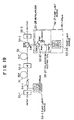
- FIG. 19 is a block diagram showing a first modification to the sixth embodiment of the present invention.
- the optical fiber amplifier shown includes an isolator 55-1, an optical demultiplexer-multiplexer 54-1, an erbium-doped-fiber (rare earth doped fiber) 51, another isolator 55-2, a dispersion compensating fiber 52, a polarization keeping optical demultiplexer-multiplexer 54-2 and a further isolator 55-3 disposed in this order from the input side.
- a pump source 53-1 is connected to the optical demultiplexer-multiplexer 54-1 while a pump source 53-2' of the depolarization multiplexing type is connected to the optical demultiplexer-multiplexer 54-2.
- the pump source 53-1 produces pump light of, for example, 0.98 ⁇ m.
- the pump source 53-2' is formed from a single pump source 53-2A', and a depolarizer 53-2B' for depolarizing pump light from the pump source 53-2A'.
- the depolarizer 53-2B' reduces the polarization dependency of the Raman optical amplifier formed from the dispersion compensating fiber 52 and is formed from a polarization keeping coupler 53-2E' for demultiplexing pump light from the pump source 53-2A', and a polarizing multiplexer (PBS) 53-2C' for orthogonally polarizing and multiplexing pump light demultiplexed by the polarization keeping coupler 53-2E' and pump light delayed by a delay line.
- PBS polarizing multiplexer
- the pump source 53-2A' outputs pump light of, for example, 1.45 to 1.49 ⁇ m (or 1.45 to 1.48 ⁇ m).
- optical demultiplexer-multiplexer of the fusion type which has no polarization keeping function is used for the optical demultiplexer-multiplexer 54-1 while another optical demultiplexer-multiplexer of the optical film type is used for the optical demultiplexer-multiplexer 54-2 so that multiplexing or demultiplexing of light may be performed while keeping polarization conditions of the light.
- pump light from the pump source 53-1 is inputted to one end of the erbium-doped-fiber 51 from the optical demultiplexer-multiplexer 54-1 together with signal light. Consequently, the signal light is amplified in the erbium-doped-fiber 51.
- depolarized pump light is introduced into an output end of the dispersion compensating fiber 52 by way of the optical demultiplexer-multiplexer 54-2 to cause Raman amplification to occur effectively in the dispersion compensating fiber 52.
- the loss of the dispersion compensating fiber 52 is compensated for by such Raman amplification.
- the present modified optical fiber amplifier may be modified such that, in place of the provision of an isolator at the input portion or at both of the input and output portions, input signal light is inputted by way of an optical circulator and output signal light is outputted by way of the optical circulator.
- the rare earth doped fiber optical amplification element formed from an erbium-doped-fiber may be formed as an optical amplification element which has a low noise figure.
- a Raman optical amplification element formed from a dispersion compensating fiber may be disposed as a front stage amplification element while a rare earth doped fiber optical amplification element formed from an erbium-doped-fiber is disposed as a rear stage amplification element.
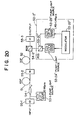
- FIG. 20 is a block diagram showing a second modification to the sixth embodiment of the present invention.
- the optical fiber amplifier shown includes an isolator 55-1, an optical demultiplexer-multiplexer 54-1, an erbium-doped-fiber (rare earth doped fiber) 51, another isolator 55-2, a dispersion compensating fiber 52, a polarization keeping optical demultiplexer-multiplexer 54-2 and a further isolator 55-3 disposed in this order from the input side.
- a pump source 53-1 is connected to the optical demultiplexer-multiplexer 54-1 while a pump source 53-2" of the modulation polarization multiplexing type is connected to the optical demultiplexer-multiplexer 54-2.
- the pump source 53-1 produces pump light of, for example, 0.98 ⁇ m.
- the pump source 53-2" is formed from a pair of pump sources 53-2A” and 53-2B", a polarizing multiplexer (PBS) 53-2C” for orthogonally polarizing and multiplexing pump light from the pump sources 53-2A” and 53-2B", and a modulator 53-2D” for modulating the pump sources 53-2A” and 53-2B" with a frequency of several hundreds kHz to 1 MHz.
- PBS polarizing multiplexer
- the pump sources 53-2A" and 53-2B" have an equal pump power and both output pump light of, for example, 1.45 to 1.49 ⁇ m (or 1.45 to 1.48 ⁇ m).
- optical demultiplexer-multiplexer of the fusion type which has no polarization keeping function is used for the optical demultiplexer-multiplexer 54-1 while another optical demultiplexer-multiplexer of the optical film type is used for the optical demultiplexer-multiplexer 54-2 so that multiplexing or demultiplexing of light may be performed while keeping polarization conditions of the light.
- pump light from the pump source 53-1 is inputted to one end of the erbium-doped-fiber 51 from the optical demultiplexer-multiplexer 54-1 together with signal light. Consequently, the signal light is amplified in the erbium-doped-fiber 51.
- modulated and orthogonally polarized multiplexed pump light having a spectrum of several hundreds kHz or more is introduced into an output end of the dispersion compensating fiber 52 by way of the optical demultiplexer-multiplexer 54-2 to cause Raman amplification to occur effectively in the dispersion compensating fiber 52.
- the loss of the dispersion compensating fiber 52 is compensated for by such Raman amplification.
- the present modified optical fiber amplifier may be modified such that, in place of the provision of an isolator at the input portion or at both of the input and output portions, input signal light is inputted by way of an optical circulator and output signal light is outputted by way of the optical circulator.
- the rare earth doped fiber optical amplification element formed from an erbium-doped-fiber may be formed as an optical amplification element which has a low noise figure.
- a Raman optical amplification element formed from a dispersion compensating fiber may be disposed as a front stage amplification element while a rare earth doped fiber optical amplification element formed from an erbium-doped-fiber is disposed as a rear stage amplification element.
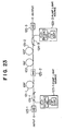
- FIG. 23 is a block diagram showing a seventh preferred embodiment of the present invention.
- the optical fiber amplifier shown includes an isolator 125-1, an optical demultiplexer-multiplexer 124-1, an erbium-doped-fiber (rare earth doped fiber) 121-1, another isolator 125-2, a silica-type-optical-fiber 122, another erbium-doped-fiber (rare earth doped fiber) 121-2, another optical demultiplexer-multiplexer 124-3, and a further isolator 125-3 disposed in this order from the input side.
- a pair of pump sources 123-1 and 123-3 for producing pump light of, for example, the 1.47 ⁇ m band (1.45 to 1.49 ⁇ m) are connected to the optical demultiplexer-multiplexers 124-1 and 124-3, respectively.
- the silica-type-optical-fiber 122 functions as a Raman optical amplifier whose amplification frequency band can be varied with a pump wavelength.
- the band characteristic of the silica-type-optical-fiber 122 depends upon the silica of the host glass and the doping material and the concentration of the core.
- each of the erbium-doped-fibers 121-1 and 121-2 functions as a rare earth doped fiber optical amplifier whose amplification frequency band and band characteristic depend upon the host glass and the doping material of the core.
- the silica-type-optical-fiber 122 has a small mode field diameter.
- the noise figure of the Raman optical amplifier formed from the silica-type-optical-fiber 122 is higher than that of the rare earth doped fiber optical amplifiers formed from the erbium-doped-fibers 121-1 and 121-2, one of the rare earth doped fiber optical amplifier is used as the front stage amplification element and the Raman optical amplifier is used as the middle stage amplification element while the other rare earth doped fiber optical amplifier is used as the rear stage amplification element in which the signal power is high, and they are connected in cascade connection to realize an optical fiber amplifier which is low in noise and has a flat band characteristic or a wide amplification frequency band.
- a rare earth doped fiber optical amplifier having a low noise figure such as an erbium-doped-fiber optical amplifier pumped with light of the 1.47 ⁇ m band
- very low signal light is amplified in a low noise condition.
- the “nonlinear effects” signifies effects which deteriorate the signal to noise ratio (SNR) such as self-phase modulation (SPM) of signal light, four wave mixing (FWM), and cross-phase modulation (XPM)
- SNR signal to noise ratio
- a Raman optical amplifier for which a silica-type-optical-fiber having a low signal power is employed is used as the middle stage amplification element.
- pump light from the pump source 123-1 is introduced into one end of the erbium-doped-fiber 121-1 by way of the optical demultiplexer-multiplexer 124-1 to pump the erbium-doped-fiber 121-1 to amplify signal light.
- residual pump light is produced in the erbium-doped-fiber 121-1, and the silica-type-optical-fiber 122 is pumped with the residual pump light so that Raman amplification may occur similarly as in a dispersion compensating fiber.
- pump light from the pump source 123-3 is introduced into an output end of the erbium-doped-fiber 121-2 by way of the optical demultiplexer-multiplexer 124-3 to pump the erbium-doped-fiber 121-2 to amplify the signal light.
- residual pump light is produced in the erbium-doped-fiber 121-2, and the silica-type-optical-fiber 122 is pumped with the residual pump light to cause Raman amplification to occur.
- the optical fiber amplifier shown in FIG. 23 employs the pump sources 123-1 and 123-3 of the 1.47 ⁇ m band in this manner, all of the erbium-doped-fibers 121-1 and 121-2 and the silica-type-optical-fiber 122 can be pumped. Consequently, a pump source 123-2 in the optical fiber amplifier can be omitted. Accordingly, the optical fiber amplifier is simplified in construction and improved in efficiency of the pump power.
- optical fiber amplifier of the present embodiment may be modified such that, in place of the provision of an isolator at the input portion or at both of the input and output portions, input signal light is inputted by way of an optical circulator and output signal light is outputted by way of the optical circulator.
- an isolator may be interposed between the silica-type-optical-fiber 122 and the erbium-doped-fiber 121-2.
- a pump source and an optical demultiplexer-multiplexer for the silica-type-optical-fiber 122 may be provided additionally.
- an optical fiber amplifier may be constructed using pump sources 123-1 to 123-3 of the 0.98 ⁇ m band and optical demultiplexer-multiplexers 124-1 to 124-3.
- silica-type-optical-fiber 122 is replaced by a dispersion compensating fiber.
- FIG. 24 is a block diagram showing a modification to the seventh embodiment of the present invention.
- the optical fiber amplifier shown includes an isolator 125-1, an optical demultiplexer-multiplexer 124-1, an erbium-doped-fiber (rare earth doped fiber) 121-1, another isolator 125-2, a silica-type-optical-fiber 122, an optical filter 126, another erbium-doped-fiber (rare earth doped fiber) 121-2, another optical demultiplexer-multiplexer 124-3, and a further isolator 125-3 disposed in this order from the input side.
- a pair of polarization multiplexing pump sources 123-1' and 123-3' are connected to the optical demultiplexer-multiplexers 124-1 and 124-3, respectively.
- the pump source 123-1' is formed from a pair of pump sources 123-1A' and 123-1B', and a polarizing multiplexer (PBS) 123-1C' for orthogonally polarizing and multiplexing pump light from the pump sources 123-1A' and 123-1B'.
- the pump sources 123-1A' and 123-1B' have an equal pump power and both output pump light of, for example, 1.45 to 1.49 ⁇ m (or 1.45 to 1.48 ⁇ m).
- the pump source 123-3' is formed from a pair of pump sources 123-3A' and 123-3B', and a polarizing multiplexer (PBS) 123-3C' for orthogonally polarizing and multiplexing pump light from the pump sources 123-3A' and 123-3B'.
- PBS polarizing multiplexer
- the pump source 123-3' is constructed as a pump source which orthogonally polarizes and multiplexes pump light in order to merely increase the pump power
- the pump wavelengths and the pump powers of the pump sources 123-3A' and 123-3B' may be different from each other.
- the erbium-doped-fiber 121-1 and the silica-type-optical-fiber 122 are either secured firmly to bobbins or like elements or accommodated in a housing so that they may not be influenced by external air and so forth.
- the isolators 125-1 to 125-3 are optical isolators of the non-polarization dependent type. Further, the optical filter 126 is used to remove or level an ASE peak in the proximity of 1.535 ⁇ m produced in the erbium-doped-fiber 121-1, and it can be omitted.
- pump light of the 1.47 ⁇ m band from the pump source 123-1' is introduced into one end of the erbium-doped-fiber 121-1 by way of the optical demultiplexer-multiplexer 124-1 to pump the erbium-doped-fiber 121-1 to amplify signal light.
- residual pump light is produced, and the silica-type-optical-fiber 122 is pumped with the residual pump light to cause Raman amplification to occur.
- pump light of 1.47 ⁇ m from the pump source 123-3' is introduced into an output end of the erbium-doped-fiber 121-2 by way of the optical demultiplexer-multiplexer 124-3 to pump the erbium-doped-fiber 121-2 to amplify the signal light.
- residual pump light is produced, and the silica-type-optical-fiber 122 is pumped with the residual pump light to cause Raman amplification to occur.
- the optical fiber amplifier shown in FIG. 24 by employing the pump sources 123-1' and 123-3' of the 1.47 ⁇ m band in this manner, all of the erbium-doped-fibers 121-1 and 121-2 and the silica-type-optical-fiber 122 can be pumped. Consequently, the pump source 123-2 in the optical fiber amplifier shown in FIG. 11 can be omitted. Accordingly, the optical fiber amplifier is simplified in construction and improved in efficiency of the pump power.
- the present modified optical fiber amplifier may be modified such that, in place of the provision of an isolator at the input portion or at both of the input and output portions, input signal light is inputted by way of an optical circulator and output signal light is outputted by way of the optical circulator.
- a pump source and an optical demultiplexer-multiplexer for the silica-type-optical-fiber 122 may be provided additionally.
- an optical fiber amplifier may be constructed using pump sources 123-1 to 123-3 of the 0.98 ⁇ m band and optical demultiplexer-multiplexers 124-1 to 124-3.
- an isolator may be interposed between the silica-type-optical-fiber 122 and the erbium-doped-fiber 121-2.
- silica-type-optical-fiber 122 is replaced by a dispersion compensating fiber.
- FIG. 25 is a block diagram showing an eighth preferred embodiment of the present invention.
- the silica-type-optical-fiber 112 is replaced by a disposition compensating fiber.
- the optical fiber amplifier shown includes an isolator 115-1, an optical demultiplexer-multiplexer 114-1, an erbium-doped-fiber (rare earth doped fiber) 111, another isolator 115-2, a silica-type-optical-fiber 112, a polarization keeping optical demultiplexer-multiplexer 114-2, and a further isolator 115-3 disposed in this order from the input side.
- a pump source 113-1 is connected to the optical demultiplexer-multiplexer 114-1, and a polarization multiplexing pump source 113-2 is connected to optical demultiplexer-multiplexer 114-2.
- the rare earth doped fiber optical amplifier and the Raman optical amplifier are employed so as to compensate for each other so that a further flattened band characteristic or a further widened amplification frequency band can be obtained.
- the rare earth doped fiber optical amplifier such as an erbium-doped-fiber amplifier pumped with 0.98 ⁇ m band or pumped with 1.47 ⁇ m
- the Raman optical amplifier formed from a silica-type-optical-fiber is used as the rear stage amplification element, and they are connected in cascade connection so that an optical fiber amplifier has a low noise characteristic and has a further flattened band characteristic or a further widened amplification frequency band.
- the rare earth doped fiber optical amplifier is used as the front amplification element while the Raman optical amplifier is used as the rear stage amplification element and they are connected in cascade connection to realize a low noise optical fiber amplifier.
- the pump source 113-1 outputs pump light of, for example, 0.98 ⁇ m.
- the pump source 113-2 is formed from a pair of pump sources 113-2A and 113-2B, and a polarizing multiplexer (PBS) 113-2C for orthogonally polarizing and multiplexing pump light from the pump sources 113-2A and 113-2B.
- PBS polarizing multiplexer
- the pump sources 113-2A and 113-2B have an equal pump power and both output pump light of, for example, 1.45 to 1.49 ⁇ m (or 1.45 to 1.48 ⁇ m)
- optical demultiplexer-multiplexer of the fusion type which has no polarization keeping function is used for the optical demultiplexer-multiplexer 114-1 while another optical demultiplexer-multiplexer of the optical film type is used for the optical demultiplexer-multiplexer 114-2 so that multiplexing or demultiplexing of light may be performed while keeping polarization conditions of the light.
- pump light from the pump source 113-1 is inputted to one end of the erbium-doped-fiber 111 by way of the optical demultiplexer-multiplexer 114-1 together with signal light. Consequently, the signal light is amplified in the erbium-doped-fiber 111.
- orthogonally polarized multiplexed pump light is introduced into an output end of the silica-type-optical-fiber 112 by way of the optical demultiplexer-multiplexer 114-2 to cause Raman amplification to occur effectively in the silica-type-optical-fiber 112.
- Raman amplification the loss of the silica-type-optical-fiber 112 is compensated for by such Raman amplification.
- the present modified optical fiber amplifier may be modified such that, in place of the provision of an isolator at the input portion or at both of the input and output portions, input signal light is inputted by way of an optical circulator and output signal light is outputted by way of the optical circulator.
- a single pump source which produces pump light of the 1.47 ⁇ m band may be provided so that it may serve as both of the pump source for the silica-type-optical-fiber and the pump source for the erbium-doped-fiber.
- a Raman optical amplifier formed from a dispersion compensating fiber is used as the amplification element on the input side (front stage amplification element) while a rare earth doped fiber optical amplifier formed from an erbium-doped-fiber is used as the amplification element on the output side (rear stage amplification element), and they are connected in cascade connection.
- the pump wavelength of the pump source for the Raman optical amplifier is approximately 1.44 ⁇ m
- the concave of the gain which appears in the proximity of approximately 1.54 ⁇ m of the rare earth doped fiber optical amplifier can be compensated for by Raman optical amplification.
- the pump wavelength of the pump source for the Raman optical amplifier is approximately 1.46 ⁇ m
- a decrease in gain which occurs in the longer wavelength side of the rare earth doped fiber optical amplifier than approximately 1.57 ⁇ m can be compensated for by the Raman optical amplification. Consequently, further leveling or widening of the band characteristic of the optical fiber amplifier can be achieved.
- the optical fiber amplifier can be constructed in the following manner so that it may have a further flattened band characteristic or a further wider amplification frequency band.
- a dispersion compensating fiber having a reduced mode field diameter is used, and in order to reduce an influence of nonlinear effects which increases as a result of the reduction of the mode field diameter, a Raman optical amplifier is employed as the amplification element on the input side (front stage amplification element) in which the signal power is low while a rare earth doped fiber optical amplifier formed from an erbium-doped-fiber is used as the amplification element on the output side (rear stage amplification element) in which the signal power is high, and they are connected in cascade connection.
- FIG. 28 is a block diagram showing a ninth preferred embodiment of the present invention.
- the optical fiber amplifier shown includes an isolator 65-1, an optical demultiplexer-multiplexer 64, an erbium-doped-fiber (rare earth doped fiber amplification element) 61, a dispersion compensating fiber (optical fiber attenuation element) 62, and another isolator 65-3 disposed in this order from the input side.
- a pump source 63 is connected to the optical demultiplexer-multiplexer 64.
- the pump source 63 produces pump light, for example, of the 1.47 ⁇ m band (1.45 to 1.49 ⁇ m).
- a rare earth doped fiber optical amplifier having a high gain sometimes suffers from unnecessary oscillations which are produced when it performs optical amplification. If such unnecessary oscillations are produced, the rare earth doped fiber optical amplifier operates but unstably.
- spontaneous emission light (ASE) of 1.53 to 1.57 ⁇ m in wavelength is produced when optical amplification is performed, and since the ASE is repetitively reflected at reflection points in the erbium-doped-fiber optical amplifier, unnecessary oscillations are liable to be produced.
- an erbium-doped-fiber optical amplifier adjusted for multiple wavelength collective amplification that is, an erbium-doped-fiber optical amplifier having a high pump rate
- unnecessary oscillations are liable to be produced at this wavelength.
- the erbium-doped-fiber optical amplifier operates unstably.
- loss medium for causing signal light to lose its power (for attenuating signal light)
- the dispersion compensating fiber 62 is pumped with remaining pump light introduced into it through the erbium-doped fiber 61 to compensate for signal light against the loss (attenuation) caused by the dispersion compensating fiber 62.
- the dispersion compensating fiber 62 functions as a loss medium.
- GR When GR is high, the erbium-doped-fiber operates unstably, and particularly when GR is higher than 1, oscillations are produced in the erbium-doped-fiber. Therefore, GR must be low, and particularly, GR is set lower than 0.02 as a target.
- the dispersion compensating fiber 62 (whose loss is represented by ⁇ (0 ⁇ 1) is provided at the following stage (output side of signal light) to the erbium-doped-fiber 61 (whose gain is represented by G), for example, by fusion connection, then an interface A appears between the erbium-doped-fiber 61 and the dispersion compensating fiber 62 as seen in FIG. 28.
- the reflectivity at the rear end of the erbium-doped-fiber 61 is represented by R1 and the reflectivity at the front end of the dispersion compensating fiber 62 is represented by R2 (here, the reflectivity R1 is a reflectivity in reflection from all parts located forwardly of the front end of the erbium-doped-fiber 61, and the reflectivity R2 is a reflectivity in reflection from all parts located rearwardly of the rear end of the dispersion compensating fiber 62).
- the parameter indicating the degree of stability of operation of the erbium-doped-fiber changes from GR to (G ⁇ )R.
- GR is considered to be a gain in one way when light takes a round.
- the parameter GR indicating the degree of stability of operation of the erbium-doped-fiber becomes low by the provision of a loss medium in this manner, unstable operation of the erbium-doped-fiber 61 can be suppressed.
- the dispersion compensating fiber 62 by pumping the dispersion compensating fiber 62 provided at the following stage to the erbium-doped-fiber 61 as shown in FIG. 28 with residual pump light from the erbium-doped-fiber 61, the dispersion compensating fiber 62 is compensated for against the loss (including leveling of the concave of the gain of the erbium-doped-fiber 61 and compensation against the reduction of the gain of the erbium-doped-fiber 61) and unstable operation of the erbium-doped-fiber 61 is simultaneously suppressed by the remaining loss.
- pump light is introduced into one end of the erbium-doped-fiber 61 from the optical demultiplexer-multiplexer 64 to pump the erbium-doped-fiber 61 to amplify signal light. Consequently, residual pump light arrives at the other end of the erbium-doped-fiber 61. Thereafter, the residual pump light is supplied to the dispersion compensating fiber 62 so that Raman amplification may occur in the dispersion compensating fiber 62.
- the pump wavelength band when signal light of the 1.55 ⁇ m band is Raman amplified is the 1.47 ⁇ m band (1.45 to 1.49 ⁇ m) which is the pump wavelength band of the erbium-doped-fiber (EDF), and accordingly, Raman amplification can be caused to occur using residual pump power when the EDF is pumped with light of the 1.47 ⁇ m band. From this reason, while optical amplification is performed by the erbium-doped-fiber 61, the dispersion compensating fiber 62 can be compensated for against the loss.
- the erbium-doped-fiber 61 the dispersion compensating fiber 62 can be compensated for against the loss.
- a wide bandwidth optical amplifier wherein the unevenness of the wavelength characteristic of the erbium-doped-fiber amplifier is leveled can be realized, and the wide bandwidth optical amplifier can be suitably applied to multiple wavelength collective amplification. Further, since the single pump source is involved, the optical fiber amplifier can be constructed in simplified structure and at a reduced cost.
- the dispersion compensating fiber 62 does not perform Raman amplification, and accordingly, compensation against the loss of the dispersion compensating fiber 62 does not take place.
- the reflectivity of the dispersion compensating fiber due to Rayleigh backscattering is ignored in the above discussion.
- the reflectivity depends on the length of the dispersion compensating fiber. Therefore, if the reflectivity cannot be ignored, an optical isolator should be added to the configuration shown in FIG. 28, for example, between the erbium-doped-fiber 61 and the dispersion compensating fiber 62.
- the addition of an optical isolator is normally effective where the Rayleigh backscattering cannot be ignored.
- optical fiber amplifier of the present embodiment may be modified such that, in place of the provision of an isolator at the input portion or at both of the input and output portions of the optical fiber amplifier, input signal light is inputted by way of an optical circulator and output signal light is outputted by way of the optical circulator.
- the pump source 63 may alternatively be formed from two pump sources and a polarizing multiplexer which orthogonally polarizes and multiplexes pump light from the pump sources or may otherwise be formed from a combination of a pump source and a depolarizer by means of which pump light is depolarized or else may generate modulated pump light.
- FIG. 29 is a block diagram showing a first modification to the ninth embodiment of the present invention.
- the optical fiber amplifier shown includes an isolator 65-1, an optical demultiplexer-multiplexer 64-1, an erbium-doped-fiber (front stage optical amplification element formed as a rare earth doped fiber amplification element) 61-1, a dispersion compensating fiber (optical fiber attenuation element) 62, another erbium-doped-fiber (rear stage optical amplification element formed as a rare earth doped fiber amplification element) 61-2, another optical demultiplexer-multiplexer 64-2 and another isolator 65-3 disposed in this order from the input side.
- a pump source 63-1 is connected to the optical demultiplexer-multiplexer 64-1, and another pump source 63-2 is connected to the optical demultiplexer-multiplexer 64-2.
- the pump sources 63-1 and 63-2 both generate pump light of, for example, the 1.47 ⁇ m band (1.45 to 1.49 ⁇ m).
- a rare earth doped fiber optical amplifier having a high gain sometimes suffers from unnecessary oscillations which are produced when it performs optical amplification, and if such unnecessary oscillations are produced, the rare earth doped fiber optical amplifier operates unstably.
- the dispersion compensating fiber 62 as a loss medium is provided at the following stage to the erbium-doped-fiber 61 as a rare earth doped fiber optical amplifier so that unstable operation of the erbium-doped-fiber 61 is suppressed.
- the gain G of the erbium-doped-fiber 61 is very high, since the GR parameter defined by the reflectivity R1, the gain G and the reflectivity RA exhibits a high value (since the gain G of the erbium-doped-fiber 61 is very high, although RA «R1, R2, an influence of the reflectivity RA cannot be ignored), even if the dispersion compensating fiber 62 is provided at the following stage to the erbium-doped-fiber 61, the effect of the loss ⁇ of it does not appear, and unstable operation of the erbium-doped-fiber 61 cannot be suppressed.
- the erbium-doped-fiber 61 is divided into front and rear stage erbium-doped-fibers, between which the dispersion compensating fiber 62 is disposed, thereby obtaining the optical fiber amplifier shown in FIG. 29.
- the dispersion compensating fiber 62 (whose loss is represented by ⁇ (0 ⁇ 1)) is provided between the erbium-doped-fibers 61-1 and 61-2 (whose gains are given by G/2), for example, by fusion connection, then an interface A' appears between the erbium-doped-fiber 61-1 and the dispersion compensating fiber 62 and another interface B' appears between the dispersion compensating fiber 62 and the erbium-doped-fiber 61-2 as seen in FIG. 57.
- the reflectivity at the front end of the erbium-doped-fiber 61-1 is represented by R1' and the reflectivity at the rear end of the erbium-doped-fiber 61-2 is represented by R2'
- the reflectivity at the interface A' is represented by RA' (RA' «R1', R2')
- the reflectivity at the interface B' is presented by RB' (RB' «R1', R2').
- the reflectivity R1' is a reflectivity in reflection from all parts located forwardly of the front end of the erbium-doped-fiber 61-1
- the reflectivity R2' is a reflectivity in reflection from all parts located rearwardly of the rear end of the erbium-doped-fiber 61-2.
- the reflectivity RA' is a reflectivity in reflection caused by a difference in reflectivity at the interface A'
- the reflectivity RB' is a reflectivity in reflection caused by a difference in reflectivity at the interface B'.
- the following GR parameters are applicable.
- GR parameters of (4) and (5) are similar to those of the parameters of (2) and (1), respectively.
- the erbium-doped-fiber 61 shown in FIG. 28 when the gain G of the erbium-doped-fiber 61 shown in FIG. 28 is very high, since the GR parameter defined by Ri, G and RA is very high, the erbium-doped-fiber 61 operates unstably, but where the erbium-doped-fiber 61 is divided into the erbium-doped-fibers 61-1 and 61-2 at the preceding and following stages as seen in FIG.
- the GR parameters of (1) and (5) can be made low, and consequently, unstable operation of the erbium-doped-fibers 61-1 and 61-2 can be suppressed.
- the dispersion compensating fiber 62 is compensated for against the loss (including leveling of the concaves of the gains of the erbium-doped-fibers 61-1 and 61-2 and compensation against the reduction of the gains of the erbium-doped-fibers 61-1 and 61-2) and unstable operation of the erbium-doped-fibers 61-1 and 61-2 is simultaneously suppressed by the remaining losses.
- pump light is inputted to one end of the erbium-doped-fiber 61-1 by way of the optical demultiplexer-multiplexer 64-1 together with signal light and pumps the erbium-doped-fiber 61-1 to amplify the signal light.
- Residual pump light which is produced in this instance arrives at the other end of the erbium-doped-fiber 61-1.
- the residual pump light is supplied into the dispersion compensating fiber 62 to cause Raman amplification to occur.
- another pump light is introduced into an output end of the erbium-doped-fiber 61-2 by way of the optical demultiplexer-multiplexer 64-2 to pump the erbium-doped-fiber 61-2 to amplify the signal light inputted into the input end of the erbium-doped-fiber 61-2. Also in this instance, residual pump light arrives at the other end of the erbium-doped-fiber 61-2. The residual pump light is supplied to the dispersion compensating fiber 62 so that Raman amplification may occur in the dispersion compensating fiber 62.
- the dispersion compensating fiber 62 causes Raman amplification to occur using the residual pump light from the erbium-doped-fibers 61-1 and 61-2 on the front and rear sides, the dispersion compensating fiber 62 exhibits a higher compensation effect as much. Consequently, a wide bandwidth optical amplifier can be realized while achieving simplification in structure and reduction in cost.
- the dispersion compensating fiber 62 does not perform Raman amplification, and accordingly, the dispersion compensating fiber 62 is not compensated for against the loss.
- the reflectivity of the dispersion compensating fiber due to Rayleigh backscattering is ignored in the above discussion.
- the reflectivity depends on the length of the dispersion compensating fiber. Therefore, if the reflectivity cannot be ignored, an optical isolator should be added to the configuration shown in FIG. 29, for example, between the erbium-doped-fiber 61-1 and the dispersion compensating fiber 62.
- the addition of an optical isolator is normally effective where the Rayleigh backscattering cannot be ignored.
- present modified optical fiber amplifier may be further modified such that, in place of the provision of an isolator at the input portion or at both of the input and output portions, input signal light is inputted by way of an optical circulator and output signal light is outputted by way of the optical circulator.
- a pump source and an optical demultiplexer-multiplexer for the dispersion compensating fiber 62 may be provided additionally.
- an optical fiber amplifier may be constructed using pump sources 133-1 to 133-3 and optical demultiplexer-multiplexers 134-1 to 134-3.
Landscapes
- Physics & Mathematics (AREA)
- Electromagnetism (AREA)
- Engineering & Computer Science (AREA)
- Plasma & Fusion (AREA)
- Optics & Photonics (AREA)
- Computer Networks & Wireless Communication (AREA)
- Signal Processing (AREA)
- Lasers (AREA)
- Optical Communication System (AREA)
- Optical Modulation, Optical Deflection, Nonlinear Optics, Optical Demodulation, Optical Logic Elements (AREA)
Claims (6)
- Vorrichtung, die optisch an eine Übertragungsleitung aus einer optischen Faser angeschlossen ist, mit:einer Dispersionskompensationsfaser (141) zur Übertragung eines optischen Signals und zum Kompensieren einer Dispersion, die dem optischen Signal aufgrund einer Übertragung über die Übertragungsleitung aus einer optischen Faser zugeteilt ist; undeiner Pumplichtquelle (142) zum Pumpen der Dispersionskompensationsfaser (141), um das optische Signal durch eine stimulierte Raman-Streuung in der Dispersionskompensationsfaser (141) zu verstärken.
- Vorrichtung nach Anspruch 1, die weiterhin einen optischen Koppler (143) zum Einführen von Pumplicht von der Pumplichtquelle (142) in die Dispersionskompensationsfaser (141) aufweist.
- Vorrichtung nach Anspruch 1 oder 2, die weiterhin einen optischen Isolator (144-2) aufweist, über welchen das optische Signal von der Dispersionskompensationsfaser (141) ausgegeben wird.
- Vorrichtung nach Anspruch 1 oder 2, die weiterhin optische Zirkulatoren zum jeweiligen Eingeben und Ausgeben von Eingangssignallicht und Ausgangssignallicht aufweist.
- Vorrichtung nach einem der vorangehenden Ansprüche, wobei die Vorrichtung ein optischer Faserverstärker ist.
- Verfahren zum Verarbeiten eines optischen Signals, das folgendes aufweist:Übertragen des optischen Signals über eine Dispersionskompensationsfaser (141), um das optische Signal zu verstärken;Kompensieren einer Dispersion, die dem optischen Signal aufgrund einer Übertragung über eine Übertragung auf einer optischen Faser zugeteilt ist; undErzeugen einer stimulierten Raman-Streuung innerhalb der Dispersionskompensationsfaser (141) durch Eingeben von Pumplicht, um das optische Signal zu verstärken.
Priority Applications (3)
| Application Number | Priority Date | Filing Date | Title |
|---|---|---|---|
| EP07013267A EP1841022A3 (de) | 1995-03-20 | 1996-03-15 | Vorrichtung und Verfahren zur Verarbeitung eines optischen Signals |
| EP02028006A EP1291986B1 (de) | 1995-03-20 | 1996-03-15 | Verfahren und Vorrichtung zur optischen Signalverarbeitung |
| EP12171988A EP2503655A3 (de) | 1995-03-20 | 1996-03-15 | Faseroptischer Verstärker und dispersionskompensierendes Fasermodul für faseroptischen Verstärker |
Applications Claiming Priority (6)
| Application Number | Priority Date | Filing Date | Title |
|---|---|---|---|
| JP61345/95 | 1995-03-20 | ||
| JP6134595 | 1995-03-20 | ||
| JP6134595 | 1995-03-20 | ||
| JP27853095 | 1995-10-26 | ||
| JP278530/95 | 1995-10-26 | ||
| JP27853095 | 1995-10-26 |
Related Child Applications (2)
| Application Number | Title | Priority Date | Filing Date |
|---|---|---|---|
| EP02028006A Division EP1291986B1 (de) | 1995-03-20 | 1996-03-15 | Verfahren und Vorrichtung zur optischen Signalverarbeitung |
| EP12171988A Division EP2503655A3 (de) | 1995-03-20 | 1996-03-15 | Faseroptischer Verstärker und dispersionskompensierendes Fasermodul für faseroptischen Verstärker |
Publications (3)
| Publication Number | Publication Date |
|---|---|
| EP0734105A2 EP0734105A2 (de) | 1996-09-25 |
| EP0734105A3 EP0734105A3 (de) | 1998-04-15 |
| EP0734105B1 true EP0734105B1 (de) | 2004-09-29 |
Family
ID=26402393
Family Applications (4)
| Application Number | Title | Priority Date | Filing Date |
|---|---|---|---|
| EP07013267A Ceased EP1841022A3 (de) | 1995-03-20 | 1996-03-15 | Vorrichtung und Verfahren zur Verarbeitung eines optischen Signals |
| EP96104143A Expired - Lifetime EP0734105B1 (de) | 1995-03-20 | 1996-03-15 | Faseroptischer Verstärker und dispersionskompensierendes Fasermodul für faseroptischen Verstärker |
| EP12171988A Withdrawn EP2503655A3 (de) | 1995-03-20 | 1996-03-15 | Faseroptischer Verstärker und dispersionskompensierendes Fasermodul für faseroptischen Verstärker |
| EP02028006A Expired - Lifetime EP1291986B1 (de) | 1995-03-20 | 1996-03-15 | Verfahren und Vorrichtung zur optischen Signalverarbeitung |
Family Applications Before (1)
| Application Number | Title | Priority Date | Filing Date |
|---|---|---|---|
| EP07013267A Ceased EP1841022A3 (de) | 1995-03-20 | 1996-03-15 | Vorrichtung und Verfahren zur Verarbeitung eines optischen Signals |
Family Applications After (2)
| Application Number | Title | Priority Date | Filing Date |
|---|---|---|---|
| EP12171988A Withdrawn EP2503655A3 (de) | 1995-03-20 | 1996-03-15 | Faseroptischer Verstärker und dispersionskompensierendes Fasermodul für faseroptischen Verstärker |
| EP02028006A Expired - Lifetime EP1291986B1 (de) | 1995-03-20 | 1996-03-15 | Verfahren und Vorrichtung zur optischen Signalverarbeitung |
Country Status (3)
| Country | Link |
|---|---|
| US (6) | US6342965B1 (de) |
| EP (4) | EP1841022A3 (de) |
| DE (2) | DE69637562D1 (de) |
Families Citing this family (150)
| Publication number | Priority date | Publication date | Assignee | Title |
|---|---|---|---|---|
| EP1841022A3 (de) * | 1995-03-20 | 2009-12-02 | Fujitsu Limited | Vorrichtung und Verfahren zur Verarbeitung eines optischen Signals |
| US6025947A (en) | 1996-05-02 | 2000-02-15 | Fujitsu Limited | Controller which controls a variable optical attenuator to control the power level of a wavelength-multiplexed optical signal when the number of channels are varied |
| DE19641577A1 (de) * | 1996-09-30 | 1998-04-02 | Deutsche Telekom Ag | Dispersionskompensationsfaser |
| WO1998036479A1 (en) * | 1997-02-18 | 1998-08-20 | Nippon Telegraph And Telephone Corporation | Optical amplifier and transmission system using the same |
| WO1999029057A1 (de) * | 1997-11-28 | 1999-06-10 | Siemens Aktiengesellschaft | Verfahren zur pegeleinstellung für optische signale |
| WO1999043107A1 (en) * | 1998-02-20 | 1999-08-26 | Ciena Corporation | Optical amplifier having an improved noise figure |
| MY132931A (en) * | 1998-05-01 | 2007-10-31 | Corning Inc | Dispersion managed optical waveguide and system with distributed amplification |
| JP3102410B2 (ja) * | 1998-05-18 | 2000-10-23 | 日本電気株式会社 | 光スイッチ |
| US6885498B2 (en) | 1998-06-16 | 2005-04-26 | Xtera Communications, Inc. | Multi-stage optical amplifier and broadband communication system |
| ATE488037T1 (de) | 1998-06-16 | 2010-11-15 | Xtera Communications Inc | Dispersionskompensierendes und verstärkendes optisches element |
| US6335820B1 (en) * | 1999-12-23 | 2002-01-01 | Xtera Communications, Inc. | Multi-stage optical amplifier and broadband communication system |
| US6344922B1 (en) | 1998-07-21 | 2002-02-05 | Corvis Corporation | Optical signal varying devices |
| US6115174A (en) | 1998-07-21 | 2000-09-05 | Corvis Corporation | Optical signal varying devices |
| US6839522B2 (en) | 1998-07-21 | 2005-01-04 | Corvis Corporation | Optical signal varying devices, systems and methods |
| EP2306605B1 (de) | 1998-07-23 | 2012-05-23 | The Furukawa Electric Co., Ltd. | Pumpeinheit für einen Ramanverstärker und Ramanverstärker, der dieselbe aufweist |
| JP3973769B2 (ja) * | 1998-08-19 | 2007-09-12 | 富士通株式会社 | 波長変換のための方法及び装置 |
| US7155095B2 (en) * | 1999-03-29 | 2006-12-26 | Furukawa Electric Co., Ltd. | Method for efficient four-wave mixing generation and short pulse generation equipment using the method |
| US6356383B1 (en) | 1999-04-02 | 2002-03-12 | Corvis Corporation | Optical transmission systems including optical amplifiers apparatuses and methods |
| JP3527671B2 (ja) * | 1999-04-23 | 2004-05-17 | 富士通株式会社 | ラマン増幅による光伝送パワーの波長特性制御方法、並びに、それを用いた波長多重光通信システムおよび光増幅器 |
| US6587261B1 (en) | 1999-05-24 | 2003-07-01 | Corvis Corporation | Optical transmission systems including optical amplifiers and methods of use therein |
| FR2794912A1 (fr) * | 1999-06-10 | 2000-12-15 | Cit Alcatel | Amplificateur raman hybride |
| US6678087B1 (en) * | 1999-08-06 | 2004-01-13 | Nippon Telegraph And Telephone Corporation | Optical amplifier and optical fiber communication system using the amplifier |
| US6611369B2 (en) | 1999-09-06 | 2003-08-26 | Furukawa Electric Co., Ltd. | Optical signal amplifier |
| JP2001102666A (ja) * | 1999-09-28 | 2001-04-13 | Fujitsu Ltd | 光増幅器 |
| FR2800219B1 (fr) | 1999-10-22 | 2006-06-30 | Algety Telecom | Procede d'ajustement de puissance pour un systeme de transmission optique a multiplexage en longueur d'onde |
| FR2800218B1 (fr) | 1999-10-22 | 2002-01-11 | Algety Telecom | Systeme de transmission par fibre optique utilisant des impulsions rz |
| EP1164412B1 (de) | 1999-12-24 | 2007-10-17 | Sumitomo Electric Industries, Ltd. | Optsche Übertragungsleitung mit Ramanverstärkung und optisches Übertragungssystem |
| CA2639993A1 (en) * | 2000-01-12 | 2001-07-19 | Xtera Communications, Inc. | Broadband fiber transmission system with raman amplifier |
| JP2001223646A (ja) | 2000-02-07 | 2001-08-17 | Nec Corp | 光増幅中継器とこれを用いた光伝送装置 |
| JP2001223420A (ja) * | 2000-02-10 | 2001-08-17 | Sumitomo Electric Ind Ltd | ラマン増幅器、光伝送システムおよび光ファイバ |
| US6344925B1 (en) | 2000-03-03 | 2002-02-05 | Corvis Corporation | Optical systems and methods and optical amplifiers for use therein |
| US6782209B2 (en) | 2000-03-03 | 2004-08-24 | Corvis Corporation | Optical transmission systems including optical amplifiers and methods |
| WO2001080467A1 (en) * | 2000-04-14 | 2001-10-25 | Institut National D'optique | Gain-locked dual stage optical amplifier |
| US6760151B1 (en) | 2000-04-27 | 2004-07-06 | Jds Uniphase Corporation | Depolarized semiconductor laser sources |
| US6681079B1 (en) * | 2000-05-18 | 2004-01-20 | Nortel Networks Limited | Optical fibre monitoring system |
| JP2001356377A (ja) | 2000-06-16 | 2001-12-26 | Kdd Submarine Cable Systems Inc | ポンプ光発生装置及びファイバラマン増幅器 |
| JP4483041B2 (ja) | 2000-07-10 | 2010-06-16 | 住友電気工業株式会社 | ラマン増幅器およびラマン増幅伝送システム |
| US6657774B1 (en) * | 2000-08-18 | 2003-12-02 | Corning Incorporated | Amplifier system with distributed and discrete Raman fiber amplifiers |
| WO2002019023A1 (fr) | 2000-08-30 | 2002-03-07 | Fujitsu Limited | Amplificateur de lumiere utilisant une amplification de raman et procede de commande de l'amplificateur |
| JP3387483B2 (ja) * | 2000-08-31 | 2003-03-17 | 日本電気株式会社 | 光直接増幅器及びその制御方法 |
| US6377396B1 (en) | 2000-09-26 | 2002-04-23 | Onetta, Inc. | Optical amplifiers with variable optical attenuation for use in fiber-optic communications systems |
| DE10048460B4 (de) * | 2000-09-29 | 2004-02-12 | Siemens Ag | Raman-Verstärker |
| US6414788B1 (en) | 2000-10-02 | 2002-07-02 | Onetta, Inc. | Optical amplifier system with transient control |
| GB0024453D0 (en) * | 2000-10-05 | 2000-11-22 | Nortel Networks Ltd | Raman amplification |
| US6417961B1 (en) | 2000-10-10 | 2002-07-09 | Onetta, Inc. | Optical amplifiers with dispersion compensation |
| US6341034B1 (en) | 2000-10-18 | 2002-01-22 | Onetta Inc. | Optical amplifier system with transient control using spectrally filtered input |
| JP2002135212A (ja) * | 2000-10-20 | 2002-05-10 | Fujitsu Ltd | 双方向伝送可能な光波長分割多重伝送システム |
| US6498677B1 (en) | 2000-10-23 | 2002-12-24 | Onetta, Inc. | Optical amplifier systems with transient control |
| JP4372330B2 (ja) * | 2000-10-30 | 2009-11-25 | 富士通株式会社 | 分布型光増幅装置、光通信用の局および光通信システム |
| US6441950B1 (en) | 2000-11-03 | 2002-08-27 | Onetta, Inc. | Distributed raman amplifier systems with transient control |
| DE10056327A1 (de) * | 2000-11-14 | 2002-05-29 | Siemens Ag | Verfahren zur Verstärkung von optischen Signalen |
| WO2002041535A2 (en) * | 2000-11-16 | 2002-05-23 | Tycom (Us) Inc. | System and method of dispersion compensation in optical communication systems |
| US7139489B2 (en) | 2000-11-16 | 2006-11-21 | Tyco Telecommunications (Us) Inc. | System and method of dispersion compensation in optical communication systems |
| DE10057659B4 (de) * | 2000-11-21 | 2004-01-15 | Siemens Ag | Optisches Übertragungssystem mit jeweils mehrere Pumpquellen aufweisenden kaskadierte Raman-Verstärkern |
| US6542287B1 (en) | 2000-12-12 | 2003-04-01 | Onetta, Inc. | Optical amplifier systems with transient control |
| US6396623B1 (en) | 2000-12-19 | 2002-05-28 | Onetta, Inc. | Wide-band optical amplifiers with interleaved gain stages |
| GB0031503D0 (en) * | 2000-12-22 | 2001-02-07 | Cit Alcatel | Optical amplifier |
| US20020118934A1 (en) * | 2001-02-23 | 2002-08-29 | Yochay Danziger | Method and system for dispersion management with Raman amplification |
| US6643057B2 (en) * | 2001-02-26 | 2003-11-04 | Corning Incorporated | Optical amplifier with reduced non-linear signal impairments by optimum pumping configuration and method for using same |
| US6603593B2 (en) * | 2001-03-13 | 2003-08-05 | Jds Uniphase Corporation | Optical transmission link including raman amplifier |
| US6943935B2 (en) * | 2001-03-16 | 2005-09-13 | Corning Incorporated | Dispersion-managed cable for raman-assisted transmission |
| US6556340B1 (en) | 2001-04-06 | 2003-04-29 | Onetta, Inc. | Optical amplifiers and upgrade modules |
| US6850360B1 (en) * | 2001-04-16 | 2005-02-01 | Bookham, Inc. | Raman amplifier systems with diagnostic capabilities |
| JP4612228B2 (ja) * | 2001-06-05 | 2011-01-12 | 富士通株式会社 | 光通信装置及び波長分割多重伝送システム |
| JP5226164B2 (ja) * | 2001-06-14 | 2013-07-03 | 富士通株式会社 | 光増幅器 |
| US6687049B1 (en) | 2001-07-03 | 2004-02-03 | Onetta, Inc. | Optical amplifiers with stable output power under low input power conditions |
| KR100396510B1 (ko) * | 2001-09-11 | 2003-09-02 | 삼성전자주식회사 | 분산 보상된 광섬유 증폭기 |
| US6577789B1 (en) | 2001-09-26 | 2003-06-10 | Onetta, Inc. | Double-pass optical amplifiers and optical network equipment |
| US6690505B1 (en) | 2001-09-28 | 2004-02-10 | Onetta, Inc. | Optical network equipment with gain transient control and automatic drift compensation |
| AU2002366169A1 (en) * | 2001-11-19 | 2003-06-10 | Photon-X, Inc. | L band optical amplifier |
| US6657776B2 (en) * | 2001-11-21 | 2003-12-02 | Lucent Technologies Inc. | Pump source including polarization scrambling in Raman amplified optical WDM systems |
| KR20030044110A (ko) * | 2001-11-28 | 2003-06-09 | 삼성전자주식회사 | 1단 구조의 광 전치 증폭기 |
| JP2003209532A (ja) * | 2002-01-16 | 2003-07-25 | Nec Corp | 直交偏波多重送信装置及びその装置に用いる多重方法 |
| EP1330056A1 (de) * | 2002-01-16 | 2003-07-23 | Lucent Technologies Inc. | Verfahren und Vorrichtung zur Ramanverstärkung in einem optischen Einrichtung |
| US6690507B2 (en) * | 2002-01-30 | 2004-02-10 | Corning Incorporated | Double-pumped raman amplifier |
| KR100407825B1 (ko) * | 2002-02-23 | 2003-12-01 | 한국전자통신연구원 | 저잡음 분산보상 하이브리드 형 광섬유 증폭기 |
| KR100407334B1 (ko) * | 2002-03-07 | 2003-11-28 | 삼성전자주식회사 | 분산보상 어븀첨가 광섬유 증폭기 |
| AU2003221350A1 (en) * | 2002-03-13 | 2003-09-22 | Nikon Corporation | Light amplifying device and method of manufacturing the device, light source device using the light amplifying device, light treatment device using the light source device, and exposure device using the light source device |
| FR2837991B1 (fr) * | 2002-04-02 | 2004-07-09 | Cit Alcatel | Procede perfectionne d'amplification raman distribuee dans une fibre optique |
| US6987896B1 (en) | 2002-04-09 | 2006-01-17 | Oplink Communications, Inc. | Optical isolator |
| US6873462B2 (en) * | 2002-04-09 | 2005-03-29 | Oplink Communications, Inc. | Three-port circulator |
| CA2481678A1 (en) * | 2002-04-12 | 2003-10-23 | Corvis Corporation | Optical communication systems including optical amplifiers and amplification methods |
| US6900933B1 (en) * | 2002-04-23 | 2005-05-31 | Oplink Communications, Inc. | Integrated two-pump combiner for optical fiber amplifiers |
| US7075712B2 (en) | 2002-05-30 | 2006-07-11 | Fujitsu Limited | Combining and distributing amplifiers for optical network and method |
| US7085496B2 (en) | 2002-05-30 | 2006-08-01 | Fujitsu Limited | Passive add/drop amplifier for optical networks and method |
| US7043101B1 (en) * | 2002-07-13 | 2006-05-09 | Finisar Corporation | Integrated optical pump module |
| JP4094905B2 (ja) * | 2002-07-25 | 2008-06-04 | 富士通株式会社 | ラマン光増幅器 |
| US6839170B2 (en) * | 2002-10-15 | 2005-01-04 | Oplink Communications, Inc. | Optical isolator |
| US7440171B2 (en) * | 2002-10-31 | 2008-10-21 | Finisar Corporation | Staged amplifier for lower noise figure and higher saturation power |
| BRPI0205361B1 (pt) * | 2002-12-20 | 2017-05-02 | FUNDAÇÃO CPQD - Centro de Pesquisa e Desenvolvimento em Telecomunicações | amplificador óptico de dupla passagem com compensação unidirecional da dispersão cromática e bloqueio dos retroespalhamentos |
| US7046432B2 (en) * | 2003-02-11 | 2006-05-16 | Coherent, Inc. | Optical fiber coupling arrangement |
| JP3961973B2 (ja) * | 2003-03-14 | 2007-08-22 | 富士通株式会社 | Otdrによる測定方法及び端局装置 |
| KR100462029B1 (ko) * | 2003-03-14 | 2004-12-18 | 한국전자통신연구원 | 광섬유 증폭기 및 이의 제어 방법 |
| EP1460736A1 (de) * | 2003-03-19 | 2004-09-22 | Alcatel | Multiwellenlänge depolarisierte Raman Pumpe |
| FR2854749B1 (fr) * | 2003-05-06 | 2005-07-22 | Cit Alcatel | Procede et dispositif d'amplification raman distribuee dans une fibre optique, par des signaux optiques de longueurs d'onde et polarisations differentes |
| US7379236B2 (en) * | 2003-07-04 | 2008-05-27 | Nippon Telegraph And Telephone Corporation | Optical fiber communication system using remote pumping |
| EP1654817A1 (de) * | 2003-08-11 | 2006-05-10 | Telecom Italia S.p.A. | In bezug auf rauschen, verstärkung und bandbreite optimierter mehrstufiger optischer verstärker |
| US7057149B2 (en) | 2003-08-26 | 2006-06-06 | Fujitsu Limited | Method and system for controlling a secondary amplifier with a primary amplifier in an optical network |
| KR100575953B1 (ko) * | 2003-10-27 | 2006-05-02 | 삼성전자주식회사 | 반사형 이득고정 반도체 광증폭기를 포함하는 광신호전송장치 및 이를 이용한 광통신 시스템 |
| KR100557170B1 (ko) * | 2003-11-14 | 2006-03-03 | 삼성전자주식회사 | 광대역 광원 |
| KR100539937B1 (ko) * | 2003-12-04 | 2005-12-28 | 삼성전자주식회사 | 이중 출력 구조의 광대역 광원 |
| JP4294459B2 (ja) * | 2003-12-12 | 2009-07-15 | 富士通株式会社 | 光増幅器 |
| US7312924B2 (en) * | 2005-09-01 | 2007-12-25 | Richard G Trissel | Polarizing multiplexer and methods for intra-oral scanning |
| JP2007274482A (ja) * | 2006-03-31 | 2007-10-18 | Fujitsu Ltd | 光伝送装置 |
| DE102006052582B4 (de) * | 2006-11-08 | 2009-10-22 | Trumpf Laser Gmbh + Co. Kg | Vorpuls-Pumplichtregelung eines lampengepumpten Lasers |
| US7843630B2 (en) * | 2007-01-08 | 2010-11-30 | Oclaro Technology Limited | Cascaded optical amplifier and control method thereof |
| US7667889B2 (en) * | 2007-02-21 | 2010-02-23 | Pyrophotonics Lasers Inc. | Methods and systems for gain control in pulsed optical amplifiers |
| US8228598B2 (en) * | 2008-01-07 | 2012-07-24 | Xtera Communications, Inc. | Optical amplifier with Raman and rare-earth-doped fiber amplifier both pumped efficiently using direct and reflected pump light |
| US8189257B2 (en) * | 2008-05-01 | 2012-05-29 | Massachusetts Institute Of Technology | Optimized cascaded raman fiber-based laser source for high efficiency mid-infrared spectral generation |
| US8111454B2 (en) * | 2009-02-13 | 2012-02-07 | Xtera Communications, Inc. | Optical communication using shared optical pumps |
| JP5304378B2 (ja) * | 2009-03-26 | 2013-10-02 | 富士通株式会社 | 光増幅器 |
| US8964801B2 (en) * | 2009-06-11 | 2015-02-24 | Esi-Pyrophotonics Lasers, Inc. | Method and system for stable and tunable high power pulsed laser system |
| JP5343722B2 (ja) * | 2009-06-15 | 2013-11-13 | 富士通株式会社 | 光増幅器及び光増幅器の偏波依存性利得抑制方法 |
| JP5353582B2 (ja) * | 2009-09-10 | 2013-11-27 | 富士通株式会社 | 光増幅装置 |
| JP5471227B2 (ja) * | 2009-09-16 | 2014-04-16 | 富士通株式会社 | 光増幅器及び光増幅方法 |
| JP5830872B2 (ja) * | 2010-03-19 | 2015-12-09 | 富士通株式会社 | 光信号処理装置、光通信方法、受信機、および光ネットワークシステム |
| US8208503B2 (en) * | 2010-05-26 | 2012-06-26 | Honeywell International Inc. | Fiber light source with high mean wavelength stability and reliability |
| US8578739B2 (en) * | 2010-10-04 | 2013-11-12 | National Applied Research Laboratories | Shorter wavelength photo-annealing apparatus for rare-earth-doped fiber and its optical assemblies under irradiation |
| EP2458751B1 (de) * | 2010-11-29 | 2013-11-20 | Xieon Networks S.à.r.l. | Optisches Kommunikationssystem und -verfahren |
| US8941911B2 (en) * | 2012-11-16 | 2015-01-27 | Viscore Technologies Inc. | Methods and devices for efficient optical fiber amplifiers |
| US8873135B2 (en) * | 2012-12-21 | 2014-10-28 | Ciena Corporation | Extended dynamic range optical amplifier |
| CN103066482A (zh) * | 2012-12-28 | 2013-04-24 | 清华大学 | 一种双向泵浦光纤激光器 |
| US9444218B1 (en) * | 2013-05-10 | 2016-09-13 | Oplink Communications, Inc. | Compact WDM optical modules |
| JP6236871B2 (ja) * | 2013-05-21 | 2017-11-29 | 富士通株式会社 | 光伝送装置および光伝送方法 |
| US9362708B2 (en) * | 2013-09-20 | 2016-06-07 | Alcatel Lucent | Compact two-stage optical amplifier |
| WO2015164044A1 (en) | 2014-04-21 | 2015-10-29 | Arris Enterprises, Inc. | Remote powering of optical splitters |
| CN106323498A (zh) * | 2015-07-03 | 2017-01-11 | 中国电力科学研究院 | 一种分布式光纤温度传感器 |
| US10784969B2 (en) * | 2016-02-18 | 2020-09-22 | Apriori Network Systems, Llc. | Secured fiber link system |
| US10284288B2 (en) * | 2016-02-18 | 2019-05-07 | Apriori Network Systems, Llc | Secured fiber link system |
| US10763962B2 (en) * | 2016-02-18 | 2020-09-01 | Apriori Network Systems, Llc. | Secured fiber link system |
| US11211765B2 (en) | 2016-10-13 | 2021-12-28 | Nlight, Inc. | Tandem pumped fiber amplifier |
| WO2018186920A2 (en) | 2017-01-12 | 2018-10-11 | Nlight, Inc. | Tandem pumped fiber laser or fiber amplifier |
| US9762020B1 (en) * | 2017-01-13 | 2017-09-12 | Gooch And Housego Plc | Bi-directionally pumped polarization maintaining fiber amplifier |
| CN107154575B (zh) * | 2017-06-27 | 2019-07-05 | 中国科学院半导体研究所 | 光纤放大器 |
| JP7040639B2 (ja) * | 2018-04-11 | 2022-03-23 | 日本電気株式会社 | 光増幅器、光通信システム及び光増幅方法 |
| WO2019198663A1 (ja) * | 2018-04-11 | 2019-10-17 | 日本電気株式会社 | 光増幅装置および光増幅方法 |
| US12149039B2 (en) * | 2018-08-30 | 2024-11-19 | Ofsfitel, Llc | Wide gain bandwidth C-band optical fiber amplifier |
| CN111384658B (zh) * | 2018-12-27 | 2021-08-06 | 山东省科学院激光研究所 | 一种拉曼光纤激光器 |
| US11621778B2 (en) * | 2019-06-11 | 2023-04-04 | Nippon Telegraph And Telephone Corporation | Optical communication system and optical communication method |
| CN112993732B (zh) * | 2019-12-17 | 2023-04-18 | 华为技术有限公司 | 一种光放大装置以及通过光放大装置的信号放大方法 |
| JPWO2021149641A1 (de) * | 2020-01-24 | 2021-07-29 | ||
| CN111490444B (zh) * | 2020-04-08 | 2022-07-15 | 武汉光迅科技股份有限公司 | 脉冲光纤放大器及光信号功率放大方法 |
| US12199664B2 (en) | 2020-05-28 | 2025-01-14 | Nippon Telegraph And Telephone Corporation | Light leakage confirmation method, light leakage confirmation apparatus and program |
| CN113937599A (zh) * | 2020-06-29 | 2022-01-14 | 中兴通讯股份有限公司 | 一种光纤放大器 |
| CN114337826A (zh) * | 2020-09-30 | 2022-04-12 | 华为技术有限公司 | 一种光放大装置以及多端口波分复用耦合器 |
| KR102607339B1 (ko) * | 2021-01-20 | 2023-11-30 | 한국전자통신연구원 | 다단 증폭을 수행하는 레이저 레이더 장치 |
| CN117080847A (zh) * | 2022-05-10 | 2023-11-17 | 成都华为技术有限公司 | 光放大器、光放大的方法以及光纤通信系统 |
| US20240162675A1 (en) * | 2022-11-15 | 2024-05-16 | Ii-Vi Delaware, Inc. | Dual-Band ASE Source Utilizing A Reflective Topology |
| US20240347998A1 (en) * | 2023-04-13 | 2024-10-17 | Cybel, LLC. | Fiber Laser With Reflective Pump Source |
| CN119447960B (zh) * | 2024-11-01 | 2025-09-16 | 广东国志激光技术有限公司 | 一种低阈值锁模的超短脉冲激光器 |
Family Cites Families (54)
| Publication number | Priority date | Publication date | Assignee | Title |
|---|---|---|---|---|
| SE307023B (de) * | 1968-01-10 | 1968-12-16 | Bofors Ab | |
| US3571607A (en) * | 1968-11-05 | 1971-03-23 | Bell Telephone Labor Inc | Highly efficient raman emission device |
| US4616898A (en) | 1980-03-31 | 1986-10-14 | Polaroid Corporation | Optical communication systems using raman repeaters and components therefor |
| GB2151868B (en) | 1983-12-16 | 1986-12-17 | Standard Telephones Cables Ltd | Optical amplifiers |
| US4699452A (en) * | 1985-10-28 | 1987-10-13 | American Telephone And Telegraph Company, At&T Bell Laboratories | Optical communications system comprising Raman amplification means |
| US4790619A (en) | 1986-04-25 | 1988-12-13 | American Telephone And Telegraph Company, At&T Bell Laboratories | Apparatus comprising Raman-active optical fiber |
| JPH0727149B2 (ja) * | 1986-11-04 | 1995-03-29 | 沖電気工業株式会社 | 光結合器 |
| JP2714611B2 (ja) | 1989-04-14 | 1998-02-16 | 日本電信電話株式会社 | 光中継器及びそれを使った光伝送路網 |
| JPH0325985A (ja) | 1989-06-23 | 1991-02-04 | Fujitsu Ltd | 光ファイバ増幅器 |
| CA2019253C (en) * | 1989-06-23 | 1994-01-11 | Shinya Inagaki | Optical fiber amplifier |
| IT1248821B (it) * | 1990-05-25 | 1995-01-30 | Pirelli Cavi Spa | Linea di telecomunicazione a fibre ottiche con amplificatori ottici a fibra attiva con ridotte riflessioni |
| US5058974A (en) * | 1989-10-06 | 1991-10-22 | At&T Bell Laboratories | Distributed amplification for lightwave transmission system |
| JPH03135081A (ja) | 1989-10-20 | 1991-06-10 | Nec Corp | 光増幅器 |
| IT1237135B (it) | 1989-10-30 | 1993-05-24 | Pirelli Cavi Spa | Gruppo di amplificazione ottico a basso rumore, con riflessione della potenza di pompaggio. |
| US5039199A (en) | 1989-12-29 | 1991-08-13 | At&T Bell Laboratories | Lightwave transmission system having remotely pumped quasi-distributed amplifying fibers |
| JPH03214681A (ja) | 1990-01-18 | 1991-09-19 | Mitsubishi Electric Corp | ファイバ形光増幅器 |
| DE4002369A1 (de) * | 1990-01-27 | 1991-08-01 | Standard Elektrik Lorenz Ag | Mehrstufiger faseroptischer verstaerker |
| US5050949A (en) * | 1990-06-22 | 1991-09-24 | At&T Bell Laboratories | Multi-stage optical fiber amplifier |
| JPH04144177A (ja) | 1990-10-05 | 1992-05-18 | Nippon Telegr & Teleph Corp <Ntt> | 光ファイバ増幅器 |
| JP2870235B2 (ja) | 1991-06-24 | 1999-03-17 | 日本電気株式会社 | 光ファイバ増幅装置 |
| JPH05142595A (ja) | 1991-11-22 | 1993-06-11 | Nec Corp | 光情報信号増幅装置 |
| IT1255953B (it) * | 1992-10-30 | 1995-11-17 | Pirelli Cavi Spa | Amplificatore ottico compatto a funzioni separate |
| US5361319A (en) * | 1992-02-04 | 1994-11-01 | Corning Incorporated | Dispersion compensating devices and systems |
| JP2806404B2 (ja) * | 1992-03-19 | 1998-09-30 | 富士通株式会社 | 光通信システムおよび光増幅器 |
| GB2265751B (en) * | 1992-03-23 | 1995-12-20 | Univ Southampton | Optical amplifier with automatic self adjusting gain spectrum |
| JPH06123902A (ja) * | 1992-05-18 | 1994-05-06 | Nippon Telegr & Teleph Corp <Ntt> | 無損失分散補償光ファイバおよびそれを用いた無損失分散補償装置 |
| AU664449B2 (en) * | 1992-06-22 | 1995-11-16 | Nec Corporation | Optical communication transmission system |
| US5283686A (en) * | 1992-07-27 | 1994-02-01 | General Instrument Corporation, Jerrold Communications | Optical systems with grating reflector |
| GB9217706D0 (en) * | 1992-08-20 | 1992-09-30 | Bt & D Technologies Ltd | Multistage fibre amplifier |
| JP2862040B2 (ja) | 1992-09-03 | 1999-02-24 | 日本電気株式会社 | 光ファイバ増幅器 |
| US5253104A (en) * | 1992-09-15 | 1993-10-12 | At&T Bell Laboratories | Balanced optical amplifier |
| JPH0697554A (ja) * | 1992-09-16 | 1994-04-08 | Nippon Telegr & Teleph Corp <Ntt> | 光ファイバ増幅器 |
| JP2760233B2 (ja) * | 1992-09-29 | 1998-05-28 | 住友電気工業株式会社 | 光通信装置 |
| EP0598554B1 (de) * | 1992-11-18 | 1999-05-12 | AT&T Corp. | Optische Faser mit negativer Dispersion |
| IT1256222B (it) * | 1992-12-23 | 1995-11-29 | Pirelli Cavi Spa | Generatore ottico di segnali ad alta potenza per impianti di telecomunicazione |
| US5712715A (en) * | 1992-12-23 | 1998-01-27 | Lucent Technologies Inc. | Optical transmission system with spatially-varying Bragg reflector |
| JPH06196788A (ja) | 1992-12-25 | 1994-07-15 | Nippon Telegr & Teleph Corp <Ntt> | 光増幅器 |
| DE4305838A1 (de) * | 1993-02-26 | 1994-09-01 | Sel Alcatel Ag | Mehrstufiger faseroptischer Verstärker |
| JPH06283790A (ja) | 1993-03-26 | 1994-10-07 | Shin Etsu Chem Co Ltd | 双方向励起型光増幅器 |
| JPH0764131A (ja) * | 1993-08-31 | 1995-03-10 | Nec Corp | 光通信装置 |
| US5430572A (en) * | 1993-09-30 | 1995-07-04 | At&T Corp. | High power, high gain, low noise, two-stage optical amplifier |
| US5363234A (en) * | 1993-10-14 | 1994-11-08 | Corning Incorporated | Amplifier having pump fiber filter |
| US5406404A (en) * | 1993-11-02 | 1995-04-11 | At&T Corp. | Method of mitigating gain peaking using a chain of fiber amplifiers |
| US5530583A (en) * | 1993-11-18 | 1996-06-25 | Matsushita Electric Industrial Co., Ltd. | Optical signal amplification apparatus and an optical fiber transmission system using the same |
| US5404413A (en) * | 1993-12-14 | 1995-04-04 | At&T Corp. | Optical circulator for dispersion compensation |
| JP2734969B2 (ja) | 1993-12-29 | 1998-04-02 | 日本電気株式会社 | 波長多重伝送用光ファイバ増幅器 |
| US6011644A (en) * | 1994-07-29 | 2000-01-04 | Corning Incorporated | Hybrid fiber amplifier |
| US5532868A (en) * | 1994-09-23 | 1996-07-02 | At&T Corp. | Apparatus and method for compensating chromatic dispersion produced in optical phase conjugation or other types of optical signal conversion |
| JPH0895095A (ja) | 1994-09-27 | 1996-04-12 | Fujitsu Ltd | 分散補償器及び光増幅器 |
| US5550671A (en) | 1995-03-02 | 1996-08-27 | Lucent Technologies Inc. | Intra-cavity optical four-wave mixer and optical communications system using the same |
| EP1841022A3 (de) * | 1995-03-20 | 2009-12-02 | Fujitsu Limited | Vorrichtung und Verfahren zur Verarbeitung eines optischen Signals |
| US5673280A (en) | 1996-02-12 | 1997-09-30 | Lucent Technologies Inc. | Article comprising low noise optical fiber raman amplifier |
| US5959750A (en) | 1996-06-06 | 1999-09-28 | Lucent Technologies Inc. | Method of upgrading transmission capacity by Raman amplification |
| US5887093A (en) * | 1997-09-12 | 1999-03-23 | Lucent Technologies Incorporated | Optical fiber dispersion compensation |
-
1996
- 1996-03-15 EP EP07013267A patent/EP1841022A3/de not_active Ceased
- 1996-03-15 DE DE69637562T patent/DE69637562D1/de not_active Expired - Lifetime
- 1996-03-15 EP EP96104143A patent/EP0734105B1/de not_active Expired - Lifetime
- 1996-03-15 EP EP12171988A patent/EP2503655A3/de not_active Withdrawn
- 1996-03-15 DE DE69633476T patent/DE69633476T2/de not_active Expired - Lifetime
- 1996-03-15 EP EP02028006A patent/EP1291986B1/de not_active Expired - Lifetime
- 1996-03-19 US US08/619,869 patent/US6342965B1/en not_active Expired - Fee Related
-
2001
- 2001-09-20 US US09/957,164 patent/US6747788B2/en not_active Expired - Fee Related
- 2001-09-25 US US09/962,170 patent/US6462862B2/en not_active Expired - Fee Related
-
2004
- 2004-04-29 US US10/834,644 patent/US6975447B2/en not_active Expired - Fee Related
-
2005
- 2005-09-26 US US11/235,600 patent/US7466477B2/en not_active Expired - Fee Related
-
2007
- 2007-03-27 US US11/728,880 patent/US7391562B2/en not_active Expired - Fee Related
Non-Patent Citations (2)
| Title |
|---|
| AOKI Y. ET AL: "EFFICIENT BACKWARD AND FORWARD PUMPING CW RAMAN AMPLIFICATION FOR InGaAsP LASER LIGHT IN SILICA FIBRES", ELECTRONICS LETTERS, 4 August 1983, VOL.19, NO.16, pages 620-622 * |
| IKEDA M.: "STIMULATED RAMAN AMPLIFICATION CHARACTERISTICS IN LONG SPAN SINGLE-MODE SILICA FIBERS", OPTICS COMMUNICATIONS, 1 October 1981, VOL.39, NO.3, pages 148-152 * |
Also Published As
| Publication number | Publication date |
|---|---|
| EP1291986A3 (de) | 2003-07-02 |
| EP1291986B1 (de) | 2008-06-11 |
| EP1841022A3 (de) | 2009-12-02 |
| US6747788B2 (en) | 2004-06-08 |
| DE69633476T2 (de) | 2005-12-01 |
| EP0734105A3 (de) | 1998-04-15 |
| EP2503655A2 (de) | 2012-09-26 |
| EP1841022A2 (de) | 2007-10-03 |
| US20070171517A1 (en) | 2007-07-26 |
| US20040207911A1 (en) | 2004-10-21 |
| EP1291986A2 (de) | 2003-03-12 |
| US20020109909A1 (en) | 2002-08-15 |
| DE69633476D1 (de) | 2004-11-04 |
| DE69637562D1 (de) | 2008-07-24 |
| US20020008901A1 (en) | 2002-01-24 |
| US7391562B2 (en) | 2008-06-24 |
| US6342965B1 (en) | 2002-01-29 |
| US7466477B2 (en) | 2008-12-16 |
| US6975447B2 (en) | 2005-12-13 |
| US6462862B2 (en) | 2002-10-08 |
| US20060018008A1 (en) | 2006-01-26 |
| EP2503655A3 (de) | 2013-02-27 |
| EP0734105A2 (de) | 1996-09-25 |
Similar Documents
| Publication | Publication Date | Title |
|---|---|---|
| EP1291986B1 (de) | Verfahren und Vorrichtung zur optischen Signalverarbeitung | |
| JP4115027B2 (ja) | 励起光発生手段と、ラマン増幅器とそれを用いた光中継器 | |
| US6172803B1 (en) | Optical amplifier and transmission system using the same | |
| EP1018666B1 (de) | Optischer Zwischenverstärker | |
| Emori et al. | 100nm bandwidth flat gain Raman amplifiers pumped and gain-equalized by 12-wavelength-channel WDM high power laser diodes | |
| Emori et al. | Broadband lossless DCF using Raman amplification pumped by multichannel WDM laser diodes | |
| JP3859256B2 (ja) | 光ファイバ増幅器 | |
| Jazayerifar et al. | Performance evaluation of DWDM communication systems with fiber optical parametric amplifiers | |
| EP0782225B1 (de) | Faserverstärker mit hoher Verstärkung und gleichmässigem Spektrum | |
| Bromage et al. | Raman amplification in the S-band | |
| Suyama et al. | 2.5 Gb/s, 4 channel WDM transmission over 1060 km using EDFAs with suppressed gain bandwidth narrowing | |
| Rosa et al. | Bandwidth extension using Raman amplifier for enhanced optical communication systems | |
| Liu et al. | Four-wave mixing in EDFAs | |
| JP2008053756A (ja) | 光ファイバ増幅器 | |
| JP4078104B2 (ja) | 光ファイバ増幅器及び光信号の増幅方法 | |
| JP3782745B2 (ja) | 分散補償ファイバモジュール及び光信号の伝送方法 | |
| Naito et al. | Active gain slope compensation in large-capacity, long-haul WDM transmission system | |
| JP4205651B2 (ja) | 光中継器 | |
| KR0183911B1 (ko) | 평탄한 고이득 및 낮은 잡음지수를 갖는 광섬유 증폭기 | |
| Gunkel et al. | 40 Gb/s RZ unrepeatered Transmission over 252 km SMF using Raman Amplification | |
| JP2006245623A (ja) | 光ファイバ増幅器 | |
| KR100581081B1 (ko) | 저잡음과 동적 입력 영역을 가지는 광증폭 장치 | |
| Suzuki et al. | Optimized Gain Distribution map for Low-noise Raman/EDF Hybrid Repeaters in Long Haul WDM Transmission | |
| KR19980014492A (ko) | 평탄한 고이득 및 낮은 잡음지수를 갖는 어븀도핑 광섬유 증폭기 | |
| Dung et al. | Reflective type Raman Amplifier for loss compensation in dispersion compensating fiber |
Legal Events
| Date | Code | Title | Description |
|---|---|---|---|
| PUAI | Public reference made under article 153(3) epc to a published international application that has entered the european phase |
Free format text: ORIGINAL CODE: 0009012 |
|
| AK | Designated contracting states |
Kind code of ref document: A2 Designated state(s): DE FR GB |
|
| PUAL | Search report despatched |
Free format text: ORIGINAL CODE: 0009013 |
|
| AK | Designated contracting states |
Kind code of ref document: A3 Designated state(s): DE FR GB |
|
| 17P | Request for examination filed |
Effective date: 19980317 |
|
| 17Q | First examination report despatched |
Effective date: 19990903 |
|
| GRAP | Despatch of communication of intention to grant a patent |
Free format text: ORIGINAL CODE: EPIDOSNIGR1 |
|
| GRAS | Grant fee paid |
Free format text: ORIGINAL CODE: EPIDOSNIGR3 |
|
| GRAA | (expected) grant |
Free format text: ORIGINAL CODE: 0009210 |
|
| AK | Designated contracting states |
Kind code of ref document: B1 Designated state(s): DE FR GB |
|
| REG | Reference to a national code |
Ref country code: GB Ref legal event code: FG4D |
|
| REF | Corresponds to: |
Ref document number: 69633476 Country of ref document: DE Date of ref document: 20041104 Kind code of ref document: P |
|
| PLBE | No opposition filed within time limit |
Free format text: ORIGINAL CODE: 0009261 |
|
| STAA | Information on the status of an ep patent application or granted ep patent |
Free format text: STATUS: NO OPPOSITION FILED WITHIN TIME LIMIT |
|
| ET | Fr: translation filed | ||
| 26N | No opposition filed |
Effective date: 20050630 |
|
| PGFP | Annual fee paid to national office [announced via postgrant information from national office to epo] |
Ref country code: FR Payment date: 20120319 Year of fee payment: 17 |
|
| PGFP | Annual fee paid to national office [announced via postgrant information from national office to epo] |
Ref country code: GB Payment date: 20120314 Year of fee payment: 17 |
|
| PGFP | Annual fee paid to national office [announced via postgrant information from national office to epo] |
Ref country code: DE Payment date: 20120411 Year of fee payment: 17 |
|
| GBPC | Gb: european patent ceased through non-payment of renewal fee |
Effective date: 20130315 |
|
| REG | Reference to a national code |
Ref country code: FR Ref legal event code: ST Effective date: 20131129 |
|
| REG | Reference to a national code |
Ref country code: DE Ref legal event code: R119 Ref document number: 69633476 Country of ref document: DE Effective date: 20131001 |
|
| PG25 | Lapsed in a contracting state [announced via postgrant information from national office to epo] |
Ref country code: GB Free format text: LAPSE BECAUSE OF NON-PAYMENT OF DUE FEES Effective date: 20130315 Ref country code: FR Free format text: LAPSE BECAUSE OF NON-PAYMENT OF DUE FEES Effective date: 20130402 Ref country code: DE Free format text: LAPSE BECAUSE OF NON-PAYMENT OF DUE FEES Effective date: 20131001 |