EP0734113A2 - Kraftwerk und Regelungsvorrichtung für dieses Kraftwerk - Google Patents
Kraftwerk und Regelungsvorrichtung für dieses Kraftwerk Download PDFInfo
- Publication number
- EP0734113A2 EP0734113A2 EP96301789A EP96301789A EP0734113A2 EP 0734113 A2 EP0734113 A2 EP 0734113A2 EP 96301789 A EP96301789 A EP 96301789A EP 96301789 A EP96301789 A EP 96301789A EP 0734113 A2 EP0734113 A2 EP 0734113A2
- Authority
- EP
- European Patent Office
- Prior art keywords
- turbine
- generator
- starter
- circuit breaker
- motor
- Prior art date
- Legal status (The legal status is an assumption and is not a legal conclusion. Google has not performed a legal analysis and makes no representation as to the accuracy of the status listed.)
- Granted
Links
Images
Classifications
-
- H—ELECTRICITY
- H02—GENERATION; CONVERSION OR DISTRIBUTION OF ELECTRIC POWER
- H02J—ELECTRIC POWER NETWORKS; CIRCUIT ARRANGEMENTS OR SYSTEMS FOR SUPPLYING OR DISTRIBUTING ELECTRIC POWER; SYSTEMS FOR STORING ELECTRIC ENERGY
- H02J9/00—Circuit arrangements for emergency or stand-by power supply, e.g. for emergency lighting
- H02J9/04—Circuit arrangements for emergency or stand-by power supply, e.g. for emergency lighting in which the distribution system is disconnected from the normal source and connected to a standby source
- H02J9/06—Circuit arrangements for emergency or stand-by power supply, e.g. for emergency lighting in which the distribution system is disconnected from the normal source and connected to a standby source with automatic change-over, e.g. UPS systems
- H02J9/066—Circuit arrangements for emergency or stand-by power supply, e.g. for emergency lighting in which the distribution system is disconnected from the normal source and connected to a standby source with automatic change-over, e.g. UPS systems characterised by the use of dynamo-electric machines
Definitions
- This invention relates to a power generation plant and a control apparatus for controlling the power generation plant having a synchronous generator coupled to a steam turbine or gas turbine, and a starter for starting the steam turbine or gas turbine by supplying electricity to the synchronous generator which can be used as a motor-generator.
- a gas turbine is started by use of a so-called thyristor starter such as a load commutated inverter (LCI) or static-frequency converters (SFC).
- a thyristor starter such as a load commutated inverter (LCI) or static-frequency converters (SFC).
- This starter is provided to be connected via a circuit breaker or disconnecting switch to a synchronous generator which is coupled to the gas turbine thereby to be able to supply an AC current having an arbitrary frequency, converted from a power supply from an electric power distribution system or from an in-house power supply, to the synchronous generator which is then driven as a synchronous motor.
- emergency power supply unit will operate when a house power supply unit installed in the power plant to supply power to auxiliary equipment fails due to some abnormality so as to substitute for the failed house power supply unit and supply power to a part of such auxiliary equipment.
- emergency power supply units there are one in which a prime mover of a diesel engine combusting heavy oil as fuel drives an AC generator, and another one in which a gas turbine generator combusting gas as fuel supplied from a gas pipeline is used. All of these units are adapted to be able to start without supply of electricity from the power system.
- Any of the emergency power supply units described above always entails a risk that it may not start at once because its stand-by equipment which has not been operated for a long time is forced to start up instantly. Namely, rotational energy or torque of the rotating shaft obtained in the course from supplying the raw fuel to combustion thereof, is then converted to electrical energy. Therefore, in any one of steps in the above course a trouble may arise, such as an ignition instability in combustion, and a reliability in starting of reciprocating movement of pistons in the case of diesel engine.
- the present invention proposes a novel emergency power supply system which can replace the conventional emergency power supply system.
- the main object of the invention is to provide a power generation plant and control apparatus therefor which is capable of supplying a highly reliable emergency power supply through use of a turbine starter according to the invention.
- the power generation plant according to the invention having a generator coupled to the rotor shaft of the turbine, and a starter coupled via a circuit breaker or disconnecting switch to the generator, which starter is adapted to supply power to the generator when starting up the turbine, is characterized by comprising another generator provided via a motor on the power input side of the starter in addition to the generator coupled to the rotor shaft of the turbine, and a control unit which executes switching operation to close and open the circuit breaker or disconnecting switch in response to a bus voltage of the house power supply which supplies electric power to operate a plurality of auxiliary equipment installed within the plant.
- the control unit described above is arranged to have a function to close the circuit breaker or disconnecting switch when an output voltage from the in-house power supply unit drops.
- the power generation plant is comprised of a first generator coupled to the rotor shaft of a turbine, a starter which is connected to the turbine generator via a circuit breaker or disconnecting switch to supply electric power to the generator when starting up the turbine, a motor which is provided on the current input side of the starter, a second generator coupled to the motor, and a control unit which causes the circuit breaker or disconnecting switch to close when the bus voltage of the in-house power supply drops for supplying, instead thereof, electric power to operate a plurality of auxiliary equipment within the power generation plant, wherein upon stop of operation of the plurality of auxiliary equipment due to the drop of bus voltage maintained by the in-house power supply, the motor is driven via the starter utilizing an inertial force of the turbine rotor persisting after the stop of operation of the auxiliary equipment so that the second generator produces electricity.
- control unit provided for controlling the power generation plant having the generator coupled to the rotor shaft of the turbine, and the starter connected via the circuit breaker or disconnecting switch to the generator for starting the turbine by supplying electric power to the generator, is characterized by comprising means for closing the circuit breaker or disconnecting switch when the bus voltage maintained by the in-house power supply unit drops which supplies power to a plurality of auxiliary equipment installed within the plant, whereby upon stoppage of operation of the plurality of auxiliary equipment due to the drop of the power supply voltage maintained by the in-house power supply, the motor connected to the input side of the starter is driven using the rotational energy of inertia of the turbine.
- the arrangement further comprises means for opening the first circuit breaker and closing the second circuit breaker when the power supply voltage of the in-house power supply drops which supplies electricity to the plurality of auxiliary equipment serving within the plant, whereby, upon stoppage of operation of the auxiliary equipment due to the drop of the power supply voltage from the in-house power supply, the motor connected to the starter on the input side thereof is urged to operate using the rotational energy of inertia of the turbine persisting after the stoppage of operation of the auxiliary equipment so that another generator connected to the motor produces electric power.
- the present invention focuses on use of this rotational energy or torque due to inertia persisting on the rotor shaft of the turbine immediately after the occurrence of abnormality.
- Another generator different from the generator coupled to the rotor shaft of the turbine is connected via the motor to the turbine starter on the input side thereof, and when the bus voltage from the in-house power supply drops suddenly, the generator coupled to the turbine and the starter which is connectable to the generator via the circuit breaker or disconnecting switch are electrically connected by closing the circuit breaker or disconnecting switch, whereby the torque due to rotational energy persisting on the shaft system of the turbine can be transformed or regenerated as useful electrical energy by means of the another generator.
- this regenerated electric power is supplied to the motor through the starter which is a thyristor starter, an electric power having a frequency characteristic appropriate to the motor can be supplied. Then, by coupling the motor to the another generator, emergency electric power can be generated reliably in a simple arrangement of components according to the invention without a need to install additional diesel engine, gas turbine engine or the like.
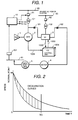
- Fig. 1 is a schematic block diagram indicative of an arrangement of a power plant of one embodiment according to the invention.
- a generator 2 is coupled to a turbine 1 such as a gas turbine so as to convert mechanical energy of turbine 1 to electrical energy.
- the electric power thus obtained is supplied to power transmission system 62 via power transformer 101 and circuit breaker 91.
- a thyristor starter called as a load commutated inverter (LCI) or static-frequency converter (SFC) is utilized, which will be referred to as LCI unit 3 hereinafter.
- LCI unit 3 load commutated inverter
- This LCI unit 3 receives an AC electrical power from power system 63 via circuit breaker 92 and power transformer 102, rectifies the AC power to DC power, then inverts the DC power into AC power having an arbitrary AC frequency to supply to the generator 2 via disconnecting switch 161. Then, the generator 2 is operated as a synchronous motor to provide a torque control necessary for the turbine 1 to start up the plant. For example, in the case of a gas turbine, and when turbine 1 attains or exceeds a self-sustaining speed that it can maintain on its own combustion energy, the disconnecting switch 161 is opened to isolate LCI unit 3 from the generator 2 thereby to start a normal operation of power generation. At this instant, circuit breaker 92 is also opened to cut off power supply from power system 63.
- a three-phase AC current from the power distribution system 63 with a commercial frequency is converted into a DC current by thyristor elements of the converter.
- the DC current is inverted into an AC current having a frequency suitable for starting up generator 2 then serving as a motor the number of revolutions of which is 0 or in the vicinity of 0, and having a current value corresponding to a start-up torque required.
- control operation over acceleration of the rotor shaft of the generator is executed through manipulation of a phase angle called as a firing angle or control angle for the thyristor circuit in the LCI unit 3, thereby LCI control device 1001 is provided therefor.
- This LCI control device 1001 receives electrical process quantity 1002 such as a current or the like which flows through the thyristor circuit, and electrical/mechanical process quantity 1004 such as of the number of revolutions of the rotor shaft of the generator, which is a target of manipulation, computes a current/torque value necessary to attain an appropriate speed rise pattern predefined in a given start-up schedule, then outputs the result of computation as control signal 1003 for use in manipulation of the target value to the phase angle described above.
- This control procedure described above is continued until the speeds of the turbine 1 and generator 2 reach a predetermined number of revolutions or the vicinity thereof.
- In-house power supply unit (emergency AC bus) 61 receives electricity for example, of 6000 V, 400 V or the like from an electric power system via a step-down transformer (not indicated), and supplies it to various auxiliary equipment which control the plant operation.
- This auxiliary equipment includes, for example, a water feed pump, fuel supply pump, fuel control valve, air flow control valve and the like, which are not indicated in the drawing.
- Undervoltage relay 201 is actuated when the bus voltage from the in-house power supply unit 61 is detected to have dropped, for example, to about 30 % of its normal output voltage due to abnormality due to lightning or failure of transformers. This actuating signal is used as various alarms.
- circuit breaker 162 motor 4 connected to the input side of LCI unit 3 via the circuit breaker 162, emergency generator 5 coupled to the motor 4, and control unit 10 added thereto which in response to a signal from undervoltage relay 201 produces a control signal to circuit breaker 91 and disconnecting switches 161, 162. Operation at the time of abnormality of in-house power supply unit 61 having the above-mentioned constitution will be described in the following.
- Control unit 10 receives an actuation signal from undervoltage relay 201 detecting an occurrence of abnormality in the in-house power supply unit 61. In response to this actuation signal, the control unit opens circuit breaker 91 to isolate the generator 2 from the power system 62 and once to release excitation of the generator 2. Then, circuit breaker 161 is closed electrically to connect LCI unit 3 with the generator 2, and, almost at the same time, excitation of the generator 2 is resumed then followed by closure of circuit breaker 162 which electrically connects the input side of LCI unit 3 with the motor 4.
- the control feature according to the invention is realized essentially through a switchable modification of configuration of the current circuit due to close/open operation of circuit breaker 91 or disconnecting switches 161, 162, or through a combination thereof with the aforementioned LCI control unit 1001 which manipulates the phase angle to an appropriate position.
- the description of this embodiment of the invention has been made by way of example of the current circuit modification control through open/close operation of the circuit breaker and disconnecting switches.
- an arrangement for implementing a proper control of phase angle by entering the number of revolutions of motor 4 as well as a target value of power generation and the like into the LCI control unit may be added as will be exercised during the steady-state operation described above.
- the axis of ordinate represents speeds of turbine 1 and the axis of abscissa represents time T.
- Both the solid curve and dotted curve indicate changes of speed of turbine 1 with time after the occurrence of abnormality in the in-house power supply unit 61.
- the solid curve indicates a conventional drop mode of turbine speed with rather a slow drop gradient.
- the embodiment of the invention when applied which regenerates the rotational energy due to inertia after the occurrence of abnormality in the in-house power supply unit, the turbine speed drops rapidly as indicated by the dotted curve due to regeneration braking acting on turbine 1.
- an emergency power supply can be obtained by a simple circuit arrangement according to the invention without installing a diesel engine, gas turbine or the like which has been required conventionally.
- a more reliable emergency power supply can be obtained.
- Any other modification of the invention such as a combination with a conventional emergency power supply should be construed within the scope of the invention.
- an emergency power supply obtained by the invention may be utilized for starting up a conventional emergency power supply unit within the scope of the invention.
- LCI unit 3 which has been used conventionally only at the time of start up of the plant, can be utilized also at the time of abnormality of the in-house power supply unit 61, its availability improved substantially, thus improving the cost performance of the plant.
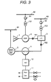
- the another embodiment of the invention described with reference to Fig. 3 basically has the same plant configuration of Fig. 1 and further includes a fuel cell power generation system 11 and an inverter unit 12.
- the control unit 10 and LCI control unit 1001 are not shown in the drawing.
- the present invention has been conceived to make use of the regenerative energy with the help of LCI unit 3 which utilizes the regenerated energy to drive the motor 4 which supplies start-up energy to emergency AC generator 5.
- fuel cell power generation system 11 is provided for use when the regenerated energy supplied from LCI unit 3 drops below a required energy level as an alternative energy source to drive the motor 4 so that emergency ac generator 5 continues its operation without interruption. More particularly, when the regenerated energy from LCI unit 3 drops below the required level, fuel cell power generation system 11 takes over LCI unit 3, which supplies power through inverter unit 12 to motor 4.
- electricity supplied from fuel cell power generation system 11 is a direct current
- motor 4 is an AC motor
- the direct current must be inverted into an alternating current using inverter unit 12.
- motor 4 is a DC motor
- an AC current from LCI unit 3 must be converted into a direct current using inverter unit 12.
- the fuel cell power generation system 11 is a typical DC current generation facility which produces a DC current through reverse reaction of electrolysis of water, which is supplied continuously with fuel of a hydrogen-rich gas obtained by reforming LNG or the like, and produces electricity through electro-chemical reaction.
- This fuel cell power generation system requires some pumps, fans and the like as its components. Capacities and quantities thereof are not substantial when viewed in a plant of a MW class.
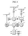
- This still another embodiment of the invention indicates a system in which switching of power supplies between from LCI unit 3 and fuel cell system 11 is implemented mechanically.
- AC motor 6 which is driven by AC power supplied from LCI unit 3
- DC motor 7 which is driven by DC power supplied from the fuel cell generation system 11, and clutch 8 which mechanically connects and disconnects the AC motor 6 and DC motor 7.
- a start up motor and a torque converter are adapted to supply a torque to the gas turbine to rotate its rotor shaft, and when its rotor speed reaches or exceeds a level of rotation enough for a self-sustaining torque to be ensured after ignition of the combustor of the gas turbine, the torque converter is released of its mechanical coupling as having done with its task of torque transfer at the instant the torque generated becomes greater than the torque transferred.
- This is a sort of mechanical clutch.
- either one of the arrangements described above has a proved performance as a mechanical decoupling mechanism, therefore, in this embodiment of the invention, either one of the above-mentioned mechanism is applied to clutch 8 to switch from the AC motor 6 to the DC motor 7.
- AC motor 6 is driven by LCI unit 3 the torque of which, however, decreases with time, therefore, at the time when the torque becomes smaller than a torque to be given by DC motor 7 which is driven by electric power supplied from fuel cell system 11, the clutch 8 mechanically coupling between AC motor 6 and DC motor 7 is decoupled to replace AC motor 6 by DC motor 7 for driving emergency generator 5 continuously.
- a reliable emergency power supply can be provided by a simple configuration without installing an emergency power supply facility which conventionally uses a diesel engine, gas turbine engine or the like.
- the LCI unit which is operated only during the start-up of the plant can be utilized also at the time of abnormality such as when a loss of power occurs in the in-house power supply unit.
- the turbine speed can be decelerated more rapidly to its turning speed.
Landscapes
- Business, Economics & Management (AREA)
- Emergency Management (AREA)
- Engineering & Computer Science (AREA)
- Power Engineering (AREA)
- Control Of Eletrric Generators (AREA)
- Stand-By Power Supply Arrangements (AREA)
Applications Claiming Priority (3)
| Application Number | Priority Date | Filing Date | Title |
|---|---|---|---|
| JP63701/95 | 1995-03-23 | ||
| JP6370195A JP3322060B2 (ja) | 1995-03-23 | 1995-03-23 | 発電プラント及び発電プラントの制御装置 |
| JP6370195 | 1995-03-23 |
Publications (3)
| Publication Number | Publication Date |
|---|---|
| EP0734113A2 true EP0734113A2 (de) | 1996-09-25 |
| EP0734113A3 EP0734113A3 (de) | 1998-09-09 |
| EP0734113B1 EP0734113B1 (de) | 2002-08-14 |
Family
ID=13236950
Family Applications (1)
| Application Number | Title | Priority Date | Filing Date |
|---|---|---|---|
| EP19960301789 Expired - Lifetime EP0734113B1 (de) | 1995-03-23 | 1996-03-15 | Kraftwerk und Regelungsvorrichtung für dieses Kraftwerk |
Country Status (4)
| Country | Link |
|---|---|
| US (1) | US5783932A (de) |
| EP (1) | EP0734113B1 (de) |
| JP (1) | JP3322060B2 (de) |
| DE (1) | DE69622904T2 (de) |
Cited By (7)
| Publication number | Priority date | Publication date | Assignee | Title |
|---|---|---|---|---|
| WO1999041821A1 (fr) * | 1998-02-16 | 1999-08-19 | France Telecom | Systeme d'alimentation electrique permettant de simplifier l'architecture des installations d'energie et de climatisation |
| WO2000074203A1 (en) * | 1999-05-26 | 2000-12-07 | Active Power, Inc. | Method and apparatus for providing an uninterruptible supply of electric power to a critical load |
| WO2002030174A3 (en) * | 2000-10-04 | 2002-10-24 | Ge Edg Inc | Rotary dynamic system power distribution unit |
| EP1104591A4 (de) * | 1998-05-19 | 2005-02-09 | Sure Power Corp | Stromversorgungssystem |
| US7422543B2 (en) | 2005-09-14 | 2008-09-09 | Conocophillips Company | Rotation coupling employing torque converter and synchronization motor |
| CN107819357A (zh) * | 2016-09-13 | 2018-03-20 | 通用电气公司 | 带有故障位置检测的隔离并联ups系统 |
| CN113389604A (zh) * | 2021-07-20 | 2021-09-14 | 赵振 | 转炉饱和蒸汽汽轮机和电机联合拖动发电自动负荷调节、运行和保护方法 |
Families Citing this family (54)
| Publication number | Priority date | Publication date | Assignee | Title |
|---|---|---|---|---|
| DE19538381C2 (de) * | 1995-10-14 | 1999-07-15 | Aeg Energietechnik Gmbh | Anordnung zur unterbrechungsfreien Stromversorgung elektrischer Verbraucher |
| WO1998025014A2 (en) * | 1996-12-03 | 1998-06-11 | Elliott Energy Systems, Inc. | Electrical system for turbine/alternator on common shaft |
| DE69720950T2 (de) * | 1997-02-07 | 2004-03-11 | Alstom (Switzerland) Ltd. | Verfahren zur Steuerung einer Kraftwerksanlage |
| FR2770339B1 (fr) | 1997-10-27 | 2003-06-13 | Commissariat Energie Atomique | Structure munie de contacts electriques formes a travers le substrat de cette structure et procede d'obtention d'une telle structure |
| DE19928711A1 (de) * | 1999-06-23 | 2000-12-28 | Abb Alstom Power Ch Ag | Kraftwerksanlage mit einer Gasturbine sowie Verfahren zu deren Betrieb |
| AU3270401A (en) * | 1999-11-16 | 2001-05-30 | Sure Power Corporation | Enhanced power system |
| AU2001271241A1 (en) * | 2000-03-20 | 2001-10-03 | Alpha Technologies, Inc. | Uninterruptible power supplies employing fuel cells |
| US6522955B1 (en) | 2000-07-28 | 2003-02-18 | Metallic Power, Inc. | System and method for power management |
| US6465910B2 (en) | 2001-02-13 | 2002-10-15 | Utc Fuel Cells, Llc | System for providing assured power to a critical load |
| US7061139B2 (en) | 2001-02-13 | 2006-06-13 | Utc Fuel Cells, Llc | System for providing assured power to a critical load |
| US6757590B2 (en) * | 2001-03-15 | 2004-06-29 | Utc Fuel Cells, Llc | Control of multiple fuel cell power plants at a site to provide a distributed resource in a utility grid |
| US20030035984A1 (en) | 2001-08-15 | 2003-02-20 | Colborn Jeffrey A. | Metal fuel cell system for providing backup power to one or more loads |
| US6911274B1 (en) | 2001-10-19 | 2005-06-28 | Metallic Power, Inc. | Fuel cell system |
| US6679280B1 (en) | 2001-10-19 | 2004-01-20 | Metallic Power, Inc. | Manifold for fuel cell system |
| US6873157B2 (en) * | 2002-04-04 | 2005-03-29 | Metallic Power, Inc. | Method of and system for determining the remaining energy in a metal fuel cell |
| US6764588B2 (en) * | 2002-05-17 | 2004-07-20 | Metallic Power, Inc. | Method of and system for flushing one or more cells in a particle-based electrochemical power source in standby mode |
| US7108095B1 (en) | 2002-11-13 | 2006-09-19 | Jerry Washington | System and method for generating power |
| US6960838B2 (en) * | 2002-11-15 | 2005-11-01 | Sprint Communications Company L.P. | Power system for a telecommunication facility |
| US7131275B2 (en) * | 2002-12-06 | 2006-11-07 | Hamilton Sundstrand | Gas turbine engine system having an electric starter motor with integral clutch |
| US7203574B2 (en) * | 2003-01-10 | 2007-04-10 | Lockheed Martin Corporation | Self-sustaining environmental control unit |
| WO2004077637A1 (en) * | 2003-02-20 | 2004-09-10 | Ebara Corporation | Power generating apparatus |
| US20050087987A1 (en) * | 2003-10-23 | 2005-04-28 | Mr. CHUN-MING KUO | [household emergency power generator] |
| US7285871B2 (en) * | 2004-08-25 | 2007-10-23 | Honeywell International, Inc. | Engine power extraction control system |
| CA2488669C (en) * | 2004-11-30 | 2012-06-12 | General Electric Canada | Isolated generator equipment compartment |
| US7552582B2 (en) * | 2005-06-07 | 2009-06-30 | Honeywell International Inc. | More electric aircraft power transfer systems and methods |
| CA2617922C (en) * | 2005-08-05 | 2015-05-12 | Power Group International, Inc. | Batteryless starter for ups |
| US7481062B2 (en) * | 2005-12-30 | 2009-01-27 | Honeywell International Inc. | More electric aircraft starter-generator multi-speed transmission system |
| US7691028B2 (en) * | 2006-05-02 | 2010-04-06 | Conocophillips Company | Mechanical soft-start system for rotating industrial equipment |
| JP2007327696A (ja) * | 2006-06-08 | 2007-12-20 | Daikin Ind Ltd | 冷凍装置 |
| US7710081B2 (en) | 2006-10-27 | 2010-05-04 | Direct Drive Systems, Inc. | Electromechanical energy conversion systems |
| US20110109101A1 (en) * | 2008-06-03 | 2011-05-12 | Leon Whitney | Insta Power |
| US8040007B2 (en) | 2008-07-28 | 2011-10-18 | Direct Drive Systems, Inc. | Rotor for electric machine having a sleeve with segmented layers |
| US7975490B2 (en) * | 2008-07-28 | 2011-07-12 | General Electric Company | Method and systems for operating a combined cycle power plant |
| US20110146293A1 (en) * | 2009-12-23 | 2011-06-23 | General Electric Company | Method for connecting a starting means to a turbomachine |
| US8555653B2 (en) * | 2009-12-23 | 2013-10-15 | General Electric Company | Method for starting a turbomachine |
| US8575779B2 (en) | 2010-02-18 | 2013-11-05 | Alpha Technologies Inc. | Ferroresonant transformer for use in uninterruptible power supplies |
| US9145833B2 (en) * | 2010-05-25 | 2015-09-29 | General Electric Company | Gas turbine startup control |
| US8881533B2 (en) | 2010-08-05 | 2014-11-11 | Rolls-Royce Corporation | Turbine engine |
| CA2825483C (en) | 2011-01-23 | 2019-11-12 | Alpha Technologies Services, Inc. | Switching systems and methods for use in uninterruptible power supplies |
| JP5738098B2 (ja) * | 2011-07-05 | 2015-06-17 | 三菱日立パワーシステムズ株式会社 | ガスタービンシステム |
| US8554433B2 (en) * | 2012-01-04 | 2013-10-08 | General Electric Company | Apparatus for driving shaft rotation and method |
| EP2644841A1 (de) * | 2012-03-29 | 2013-10-02 | Alstom Technology Ltd | Verfahren zum Betreiben eines Turbinenmotors nach Flammenaus |
| US9234916B2 (en) | 2012-05-11 | 2016-01-12 | Alpha Technologies Inc. | Status monitoring cables for generators |
| WO2013168282A1 (ja) * | 2012-05-11 | 2013-11-14 | 東芝三菱電機産業システム株式会社 | 直流電圧検出器およびそれを用いた電力変換装置 |
| CN104487678B (zh) * | 2012-08-03 | 2017-06-06 | 株式会社日立制作所 | 双轴式燃气轮机发电系统、燃气轮机系统的控制装置以及控制方法 |
| US10521518B2 (en) | 2012-12-05 | 2019-12-31 | Deif A/S | Emulating power system operations |
| US9099882B2 (en) * | 2013-01-18 | 2015-08-04 | Caterpillar Inc. | Turbine engine hybrid power supply |
| EP2759689B8 (de) * | 2013-01-28 | 2016-09-21 | General Electric Technology GmbH | Notstromversorgungssystem mit Wasserstoff betriebener Brennstoffzelle |
| JP2015126540A (ja) * | 2013-12-25 | 2015-07-06 | 株式会社東芝 | 原子力発電所用非常電源システムおよび非常用独立電源 |
| BR112018004887A2 (en) | 2015-09-13 | 2018-10-09 | Alpha Technologies Inc. | power control systems and methods. |
| US10381867B1 (en) | 2015-10-16 | 2019-08-13 | Alpha Technologeis Services, Inc. | Ferroresonant transformer systems and methods with selectable input and output voltages for use in uninterruptible power supplies |
| CN105406585A (zh) * | 2015-12-11 | 2016-03-16 | 上海查尔斯电子有限公司 | 一种用于核电站的应急电电源 |
| CA3069966A1 (en) | 2017-07-14 | 2019-01-17 | Alpha Technologies Services, Inc. | Voltage regulated ac power supply systems and methods |
| US11171589B2 (en) * | 2019-11-20 | 2021-11-09 | Mitsubishi Power Americas, Inc. | Systems and methods for starting steam turbines |
Family Cites Families (9)
| Publication number | Priority date | Publication date | Assignee | Title |
|---|---|---|---|---|
| US4119861A (en) * | 1975-10-15 | 1978-10-10 | Tokyo Shibaura Electric Company, Ltd. | Starting apparatus for gas turbine-generator mounted on electric motor driven motorcar |
| US4168459A (en) * | 1977-10-25 | 1979-09-18 | Precise Power Corporation | Non-interruptible power supply systems |
| US4403292A (en) * | 1979-05-30 | 1983-09-06 | Sundstrand Corporation | Control for an electrical generating and distribution system, and method of operation |
| DE3836563A1 (de) * | 1987-10-29 | 1989-05-18 | Mitsubishi Electric Corp | Antriebssystem fuer eine kuehlmittelpumpe in einem atomkraftwerk |
| US4967096A (en) * | 1989-01-26 | 1990-10-30 | Sundstrand Corporation | Cross-start bus configuration for a variable speed constant frequency electric power system |
| AU627952B2 (en) * | 1989-12-11 | 1992-09-03 | Westinghouse Electric Corporation | Gas turbine control system having maximum instantaneous load pickup limiter |
| JPH0454227A (ja) * | 1990-06-22 | 1992-02-21 | Toshiba Corp | ガスタービン始動方法 |
| DE4215844A1 (de) * | 1992-04-28 | 1993-11-04 | Asea Brown Boveri | Mehrphasiges schaltsystem und generatoranordnung mit einem solchen schaltsystem |
| JPH06261454A (ja) * | 1993-03-09 | 1994-09-16 | Hitachi Ltd | 発電設備の始動装置 |
-
1995
- 1995-03-23 JP JP6370195A patent/JP3322060B2/ja not_active Expired - Lifetime
-
1996
- 1996-03-15 DE DE69622904T patent/DE69622904T2/de not_active Expired - Lifetime
- 1996-03-15 EP EP19960301789 patent/EP0734113B1/de not_active Expired - Lifetime
- 1996-03-21 US US08/619,185 patent/US5783932A/en not_active Expired - Lifetime
Cited By (11)
| Publication number | Priority date | Publication date | Assignee | Title |
|---|---|---|---|---|
| WO1999041821A1 (fr) * | 1998-02-16 | 1999-08-19 | France Telecom | Systeme d'alimentation electrique permettant de simplifier l'architecture des installations d'energie et de climatisation |
| FR2775138A1 (fr) * | 1998-02-16 | 1999-08-20 | France Telecom | Systeme d'alimentation electrique permettant de simplifier l'architecture des installations d'energie et de climatisation |
| US6483206B1 (en) | 1998-02-16 | 2002-11-19 | France Telecom | Electric power supply system for simplifying the architecture of power and air-conditioning installations |
| EP1104591A4 (de) * | 1998-05-19 | 2005-02-09 | Sure Power Corp | Stromversorgungssystem |
| WO2000074203A1 (en) * | 1999-05-26 | 2000-12-07 | Active Power, Inc. | Method and apparatus for providing an uninterruptible supply of electric power to a critical load |
| US6255743B1 (en) | 1999-05-26 | 2001-07-03 | Active Power, Inc. | Method and apparatus for providing an uninterruptible supply of electric power to a critical load |
| WO2002030174A3 (en) * | 2000-10-04 | 2002-10-24 | Ge Edg Inc | Rotary dynamic system power distribution unit |
| US7422543B2 (en) | 2005-09-14 | 2008-09-09 | Conocophillips Company | Rotation coupling employing torque converter and synchronization motor |
| CN107819357A (zh) * | 2016-09-13 | 2018-03-20 | 通用电气公司 | 带有故障位置检测的隔离并联ups系统 |
| CN107819357B (zh) * | 2016-09-13 | 2023-01-24 | Abb瑞士股份有限公司 | 带有故障位置检测的隔离并联ups系统 |
| CN113389604A (zh) * | 2021-07-20 | 2021-09-14 | 赵振 | 转炉饱和蒸汽汽轮机和电机联合拖动发电自动负荷调节、运行和保护方法 |
Also Published As
| Publication number | Publication date |
|---|---|
| US5783932A (en) | 1998-07-21 |
| DE69622904T2 (de) | 2003-04-10 |
| DE69622904D1 (de) | 2002-09-19 |
| JPH08265991A (ja) | 1996-10-11 |
| EP0734113B1 (de) | 2002-08-14 |
| EP0734113A3 (de) | 1998-09-09 |
| JP3322060B2 (ja) | 2002-09-09 |
Similar Documents
| Publication | Publication Date | Title |
|---|---|---|
| US5783932A (en) | Power generation plant and control apparatus therefor | |
| US7122916B2 (en) | Multi-unit power generation system for stand-alone and grid connected operation | |
| US8916985B2 (en) | Gas turbine start with frequency convertor | |
| US9577471B2 (en) | Power system for providing an uninterruptible power supply to an external load | |
| KR20020090142A (ko) | 보조 전원 시스템 및 그 작동 방법 | |
| WO2003052922A1 (en) | Turbine generator start method and turbine generation system | |
| KR20000036045A (ko) | 주 이동기를 가진 비동기식 장치 및 인버터/정류기를 포함하는 격리된 전기 시스템 | |
| PL170640B1 (pl) | Zespól turbin gazowych i sposób zwiekszania obrotów zespolu turbin gazowych PL PL PL | |
| EP0271498A1 (de) | Notaggregat | |
| US8436488B2 (en) | Semi-direct variable speed drive with N+1 power availability | |
| EP0007389B1 (de) | System und Verfahren zur Energierückgewinnung | |
| WO2002044555A1 (en) | Flywheel based ups apparatus and method for using same | |
| JPH10121908A (ja) | 発電設備のターニング装置 | |
| RU2714022C2 (ru) | Способ адаптивного автоматического регулирования давления наддувочного воздуха дизель-генератора | |
| KR20250088763A (ko) | 비동기 기계의 안전한 전력 그리드 연결을 갖춘 발전 장치 | |
| WO2025037451A1 (ja) | 保護システムおよび保護装置 | |
| RU2139444C1 (ru) | Автономная ветродизельэлектрическая установка | |
| GB2630921A (en) | Electrically starting a gas turbine engine | |
| JP2009047087A (ja) | 揚水発電装置およびその制御方法 | |
| JPH10257696A (ja) | 非常電源装置 | |
| JP3470837B2 (ja) | 発電プラントの起動停止装置 | |
| CN218347461U (zh) | 车载燃气轮机机组辅助装置动力系统 | |
| KR102699112B1 (ko) | 가스터빈 기동장치 보조 제어방법 | |
| CN120777073A (zh) | 一种加速汽轮机中速暖机的方法和装置 | |
| Dovganyuk et al. | Specifics of Electromagnetic and Electromechanical Processes for Starting Up Forced-Draft Systems of High-Capacity TPP Power Generating Units |
Legal Events
| Date | Code | Title | Description |
|---|---|---|---|
| PUAI | Public reference made under article 153(3) epc to a published international application that has entered the european phase |
Free format text: ORIGINAL CODE: 0009012 |
|
| 17P | Request for examination filed |
Effective date: 19960404 |
|
| AK | Designated contracting states |
Kind code of ref document: A2 Designated state(s): DE FR |
|
| PUAL | Search report despatched |
Free format text: ORIGINAL CODE: 0009013 |
|
| AK | Designated contracting states |
Kind code of ref document: A3 Designated state(s): DE FR |
|
| 17Q | First examination report despatched |
Effective date: 20000803 |
|
| GRAG | Despatch of communication of intention to grant |
Free format text: ORIGINAL CODE: EPIDOS AGRA |
|
| GRAG | Despatch of communication of intention to grant |
Free format text: ORIGINAL CODE: EPIDOS AGRA |
|
| GRAH | Despatch of communication of intention to grant a patent |
Free format text: ORIGINAL CODE: EPIDOS IGRA |
|
| RIN1 | Information on inventor provided before grant (corrected) |
Inventor name: UDA, KENGO Inventor name: NAMBA, SHIGEAKI |
|
| GRAH | Despatch of communication of intention to grant a patent |
Free format text: ORIGINAL CODE: EPIDOS IGRA |
|
| GRAA | (expected) grant |
Free format text: ORIGINAL CODE: 0009210 |
|
| AK | Designated contracting states |
Kind code of ref document: B1 Designated state(s): DE FR |
|
| REF | Corresponds to: |
Ref document number: 69622904 Country of ref document: DE Date of ref document: 20020919 |
|
| ET | Fr: translation filed | ||
| PLBE | No opposition filed within time limit |
Free format text: ORIGINAL CODE: 0009261 |
|
| STAA | Information on the status of an ep patent application or granted ep patent |
Free format text: STATUS: NO OPPOSITION FILED WITHIN TIME LIMIT |
|
| 26N | No opposition filed |
Effective date: 20030515 |
|
| REG | Reference to a national code |
Ref country code: FR Ref legal event code: PLFP Year of fee payment: 20 |
|
| PGFP | Annual fee paid to national office [announced via postgrant information from national office to epo] |
Ref country code: DE Payment date: 20150310 Year of fee payment: 20 |
|
| PGFP | Annual fee paid to national office [announced via postgrant information from national office to epo] |
Ref country code: FR Payment date: 20150309 Year of fee payment: 20 |
|
| REG | Reference to a national code |
Ref country code: DE Ref legal event code: R071 Ref document number: 69622904 Country of ref document: DE |