EP0734305B1 - Procede pour le reglage d'alesoirs et outils analogues - Google Patents
Procede pour le reglage d'alesoirs et outils analogues Download PDFInfo
- Publication number
- EP0734305B1 EP0734305B1 EP95903274A EP95903274A EP0734305B1 EP 0734305 B1 EP0734305 B1 EP 0734305B1 EP 95903274 A EP95903274 A EP 95903274A EP 95903274 A EP95903274 A EP 95903274A EP 0734305 B1 EP0734305 B1 EP 0734305B1
- Authority
- EP
- European Patent Office
- Prior art keywords
- camera
- diameter
- measuring
- cutting edge
- inclination
- Prior art date
- Legal status (The legal status is an assumption and is not a legal conclusion. Google has not performed a legal analysis and makes no representation as to the accuracy of the status listed.)
- Expired - Lifetime
Links
- 238000000034 method Methods 0.000 title claims description 27
- 238000005520 cutting process Methods 0.000 claims description 63
- 230000000717 retained effect Effects 0.000 claims description 2
- 238000005259 measurement Methods 0.000 claims 1
- 238000006243 chemical reaction Methods 0.000 description 4
- 238000003754 machining Methods 0.000 description 2
- 239000000463 material Substances 0.000 description 2
- 239000000523 sample Substances 0.000 description 2
- 230000001154 acute effect Effects 0.000 description 1
- 238000001514 detection method Methods 0.000 description 1
- 238000006073 displacement reaction Methods 0.000 description 1
- 238000004519 manufacturing process Methods 0.000 description 1
- 238000011326 mechanical measurement Methods 0.000 description 1
- 238000009958 sewing Methods 0.000 description 1
- 230000035939 shock Effects 0.000 description 1
Images
Classifications
-
- B—PERFORMING OPERATIONS; TRANSPORTING
- B23—MACHINE TOOLS; METAL-WORKING NOT OTHERWISE PROVIDED FOR
- B23Q—DETAILS, COMPONENTS, OR ACCESSORIES FOR MACHINE TOOLS, e.g. ARRANGEMENTS FOR COPYING OR CONTROLLING; MACHINE TOOLS IN GENERAL CHARACTERISED BY THE CONSTRUCTION OF PARTICULAR DETAILS OR COMPONENTS; COMBINATIONS OR ASSOCIATIONS OF METAL-WORKING MACHINES, NOT DIRECTED TO A PARTICULAR RESULT
- B23Q17/00—Arrangements for observing, indicating or measuring on machine tools
- B23Q17/09—Arrangements for observing, indicating or measuring on machine tools for indicating or measuring cutting pressure or for determining cutting-tool condition, e.g. cutting ability, load on tool
- B23Q17/0904—Arrangements for observing, indicating or measuring on machine tools for indicating or measuring cutting pressure or for determining cutting-tool condition, e.g. cutting ability, load on tool before or after machining
- B23Q17/0919—Arrangements for measuring or adjusting cutting-tool geometry in presetting devices
- B23Q17/0933—Cutting angles of milling cutters
-
- B—PERFORMING OPERATIONS; TRANSPORTING
- B23—MACHINE TOOLS; METAL-WORKING NOT OTHERWISE PROVIDED FOR
- B23D—PLANING; SLOTTING; SHEARING; BROACHING; SAWING; FILING; SCRAPING; LIKE OPERATIONS FOR WORKING METAL BY REMOVING MATERIAL, NOT OTHERWISE PROVIDED FOR
- B23D77/00—Reaming tools
- B23D77/02—Reamers with inserted cutting edges
- B23D77/04—Reamers with inserted cutting edges with cutting edges adjustable to different diameters along the whole cutting length
-
- B—PERFORMING OPERATIONS; TRANSPORTING
- B23—MACHINE TOOLS; METAL-WORKING NOT OTHERWISE PROVIDED FOR
- B23D—PLANING; SLOTTING; SHEARING; BROACHING; SAWING; FILING; SCRAPING; LIKE OPERATIONS FOR WORKING METAL BY REMOVING MATERIAL, NOT OTHERWISE PROVIDED FOR
- B23D77/00—Reaming tools
- B23D77/02—Reamers with inserted cutting edges
- B23D77/04—Reamers with inserted cutting edges with cutting edges adjustable to different diameters along the whole cutting length
- B23D77/048—Reamers with inserted cutting edges with cutting edges adjustable to different diameters along the whole cutting length by means of conical screw threads
-
- B—PERFORMING OPERATIONS; TRANSPORTING
- B23—MACHINE TOOLS; METAL-WORKING NOT OTHERWISE PROVIDED FOR
- B23Q—DETAILS, COMPONENTS, OR ACCESSORIES FOR MACHINE TOOLS, e.g. ARRANGEMENTS FOR COPYING OR CONTROLLING; MACHINE TOOLS IN GENERAL CHARACTERISED BY THE CONSTRUCTION OF PARTICULAR DETAILS OR COMPONENTS; COMBINATIONS OR ASSOCIATIONS OF METAL-WORKING MACHINES, NOT DIRECTED TO A PARTICULAR RESULT
- B23Q17/00—Arrangements for observing, indicating or measuring on machine tools
- B23Q17/24—Arrangements for observing, indicating or measuring on machine tools using optics or electromagnetic waves
-
- G—PHYSICS
- G01—MEASURING; TESTING
- G01B—MEASURING LENGTH, THICKNESS OR SIMILAR LINEAR DIMENSIONS; MEASURING ANGLES; MEASURING AREAS; MEASURING IRREGULARITIES OF SURFACES OR CONTOURS
- G01B11/00—Measuring arrangements characterised by the use of optical techniques
- G01B11/26—Measuring arrangements characterised by the use of optical techniques for measuring angles or tapers; for testing the alignment of axes
-
- B—PERFORMING OPERATIONS; TRANSPORTING
- B23—MACHINE TOOLS; METAL-WORKING NOT OTHERWISE PROVIDED FOR
- B23D—PLANING; SLOTTING; SHEARING; BROACHING; SAWING; FILING; SCRAPING; LIKE OPERATIONS FOR WORKING METAL BY REMOVING MATERIAL, NOT OTHERWISE PROVIDED FOR
- B23D2277/00—Reaming tools
- B23D2277/20—Number of cutting edges
- B23D2277/201—One
-
- Y—GENERAL TAGGING OF NEW TECHNOLOGICAL DEVELOPMENTS; GENERAL TAGGING OF CROSS-SECTIONAL TECHNOLOGIES SPANNING OVER SEVERAL SECTIONS OF THE IPC; TECHNICAL SUBJECTS COVERED BY FORMER USPC CROSS-REFERENCE ART COLLECTIONS [XRACs] AND DIGESTS
- Y10—TECHNICAL SUBJECTS COVERED BY FORMER USPC
- Y10T—TECHNICAL SUBJECTS COVERED BY FORMER US CLASSIFICATION
- Y10T408/00—Cutting by use of rotating axially moving tool
- Y10T408/03—Processes
-
- Y—GENERAL TAGGING OF NEW TECHNOLOGICAL DEVELOPMENTS; GENERAL TAGGING OF CROSS-SECTIONAL TECHNOLOGIES SPANNING OVER SEVERAL SECTIONS OF THE IPC; TECHNICAL SUBJECTS COVERED BY FORMER USPC CROSS-REFERENCE ART COLLECTIONS [XRACs] AND DIGESTS
- Y10—TECHNICAL SUBJECTS COVERED BY FORMER USPC
- Y10T—TECHNICAL SUBJECTS COVERED BY FORMER US CLASSIFICATION
- Y10T408/00—Cutting by use of rotating axially moving tool
- Y10T408/16—Cutting by use of rotating axially moving tool with control means energized in response to activator stimulated by condition sensor
- Y10T408/175—Cutting by use of rotating axially moving tool with control means energized in response to activator stimulated by condition sensor to control relative positioning of Tool and work
-
- Y—GENERAL TAGGING OF NEW TECHNOLOGICAL DEVELOPMENTS; GENERAL TAGGING OF CROSS-SECTIONAL TECHNOLOGIES SPANNING OVER SEVERAL SECTIONS OF THE IPC; TECHNICAL SUBJECTS COVERED BY FORMER USPC CROSS-REFERENCE ART COLLECTIONS [XRACs] AND DIGESTS
- Y10—TECHNICAL SUBJECTS COVERED BY FORMER USPC
- Y10T—TECHNICAL SUBJECTS COVERED BY FORMER US CLASSIFICATION
- Y10T408/00—Cutting by use of rotating axially moving tool
- Y10T408/21—Cutting by use of rotating axially moving tool with signal, indicator, illuminator or optical means
Definitions
- the invention relates to a method for adjusting the diameter of Reamers and similar cutting tools, with the features of the generic term of claim 1.
- Machining is used to produce precise bores with narrow manufacturing tolerances, special cutting tools, mostly So-called reamers are used, the cutting blades are interchangeable and is adjustably attached to a shaft. These cutting knives need to a change and before each new use to a specified diameter can be set. Most of the time, the cutting knives are also opposed the feed direction to avoid material jams at the cutting entrance slightly inclined radially inwards.
- the setting of the cutting knife takes place with the help of set screws or provided on the tool shank the like, and for fixing the cutting knife is at least one Clamping screw provided.
- Another known method on which the preamble of claim 1 is based, for setting the cutting tools which the present invention builds on uses a device with two coordinate slides. on the one hand the tool and on the other hand a camera is mounted. By adjusting the slide the determined by the cutting edge of the tool diameter plane in the Brought focus level to the camera.
- the Cutting edge and on the other hand the guide line opposite on the shaft on a monitor connected to the camera Reference position brought to the camera and the path between the The cutting edge and the guide line are determined using precise scales. This travel distance corresponds to the effective diameter of the cutting tool.
- the setting process can also be followed on the monitor, until the target dimension is reached.
- the through is first the cutting knife certain diameter plane into the focus plane of the Brought to the camera by the tool with the help of this Move the coordinate slide and rotate it in the coordinate slide, until a sharp picture of the diameter appears on the monitor. Because cameras of the present type have a very shallow depth of field even slight canting is visible. If the desired position in the Focal plane is reached, the coordinate slide carrying the tool fixed. The subsequent traversing processes are carried out using the the coordinate sled receiving the camera in the present context also called slide. However, it is also possible to fix the measuring slide with the camera and the traversing processes with the help of the coordinate slide of the tool.
- the shank of the tool is not is completely straight in the tool holder. That would cause that in the measuring process not the exact diameter, but something longer, obliquely extending through the shaft would be determined.
- the step is therefore additionally provided that the camera at the same time with the detection of the position (item II) of the rear guide line the shaft detects any inclination of this guide line, and that the determined sewing angle during the subsequent determination of the travel path via a cos function to recalculate the measured travel distance is used.
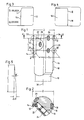
- Fig. 1 is a shaft 10 of a cutting tool to be adjusted shown on which a cutting knife 12 is attached. How in particular 2 is located diametrically opposite the one with 14 designated cutting edge of the cutting knife partially in the shaft 10 recessed guide rails running along a surface line of the shaft 16, whose apex line is exactly opposite the cutting edge 14 and in the present context is to be referred to as guide line 18.
- the cutting knife 12 is with the help of a clamping screw 20 and Clamping plate 22 held on the shaft. Allow two setscrews 24 and 26 after loosening the clamping screw 20, a displacement of the Cutting knife 12 to the right and left in Figs. 1 and 2 and, since they are at a distance one above the other, also an inclination adjustment of the cutting knife 12 with respect to the perpendicular in FIG. 1.
- the cutting edge 14 does not run exactly parallel to the axis of rotation 30 of the shaft 10. Rather, at the top end in Fig. 1, an upwardly tapered section 32 is provided, the entry in making a hole easier. This section ends in a position I, the In the section plane 2-2 of FIG. 2 lies.
- the cutting edge 14 runs from here in the further course slightly with a very acute angle ⁇ (Fig. 5) to the axis of rotation 30 back.
- the guide bar 18 also has an upper section 34 which is tapered towards the top of the tool and only at that point marked II, which is also in the section plane 2-2, reached the guide bar 16 is the measure determining the diameter.
- the diameter D taken in the section plane 2-2 is therefore the effective for the diameter of the tool determining the borehole size.
- this diameter D is specified for a machining operation, but also the angle of inclination ⁇ , by means of which an excessive material build-up and reaction pressure in the back areas of the cutting edge are avoided.
- the angle of inclination ⁇ must therefore also be set during an adjustment process. This is not done directly by adjusting the angle, but rather by determining or determining a further diameter D1 at a distance L parallel to the axis of rotation of the shaft 10, which is calculated using the tan function of the angle ⁇ according to the following relationships.
- the conversion of the angle ⁇ into a diameter D1 takes into account the Practical conditions. Theoretically, it would also be possible to change the angle of inclination ⁇ display and set directly. Since it is a very small one Angle, this would not be vivid. In practice, therefore, it is far preferable if the slope is defined by length measures here is the distance L between the positions of the two diameters D. and D1, and the change in length of the diameter over the distance L from Value D on D1.
- the plane of the diameter D1 runs through the lower set screw 26 so that rotation of this lower set screw 26 directly adjusts the diameter D1.
- the position the cutting edge 14 in the by the diameter D1 or the lower Set screw 26 certain level has been designated III in Fig. 1.
- the camera not shown, with the associated coordinate slide move to measuring point I on the cutting edge.
- the searched diameter D setting diameter
- the measuring carriage carrying the camera is returned to the Move the position shown in Fig. 3, in which again the measuring position I recorded becomes.
- the distance traveled between measuring position II (Fig. 4) and I (Fig. 3) Travel path corresponds exactly to the current effective diameter of the tool.
- the travel distance, i.e. the diameter D is left superimposed in the monitor according to FIG. 3.
- the camera remains pointed at the cutting knife, and it the image shown in Fig. 3 continues to appear on the monitor.
- the changes the values of D and D1 during the setting process can therefore are constantly monitored on the monitor.
- the desired diameter dimension D can be produced.
- the diameter D1 explained above should correspond to the Tilt angle ⁇ of the cutting edge can be set.
- the camera detects the angle of inclination ⁇ of the cutting edge, and this becomes according to the equations given in the desired diameter Converted to D1.
- the respective value of D1 is shown in the monitor image at the bottom left shown in FIG. 3. If by operating the set screws 24,26 both the dimension of D and the dimension of D1 are changed so that the corresponding predefined values appear on the monitor, the setting process is finished.
- the cutting knife is made using the Clamping screw 20 fixed.
- Position III (diameter D1) is reached without having to move the camera slide again. In particular, it is not necessary to repeat between points I, II and III back and forth, as is the case with the prior art, so that the associated expenditure of time and the inaccuracies caused thereby omitted.
- the procedure described presupposes, however, that the shaft 10 is held completely straight in the tool holder. In practice it is however, quite often that either the tool holder or the tool shank have a shock due to previous loads.
- the camera detects position II on the back of the The inclination of the shaft, and the computer calculates the travel distance between points II and I according to a suitable angular function this angle back. The same applies to the determination of the Diameter D1.
- the particular advantage of the invention is that after the return the camera in position I of the cutting edge both the diameter D and also the diameter D1 is set without any further movement of the camera can and that the cutting edge with the position I during which always remains visible on the monitor. Even after the termination of the Adjustment process and tightening the clamping screw 20 can still once carried out a final check without moving or a shift of the values by tightening the clamping screw can be corrected.
Landscapes
- Engineering & Computer Science (AREA)
- Mechanical Engineering (AREA)
- Physics & Mathematics (AREA)
- Optics & Photonics (AREA)
- General Physics & Mathematics (AREA)
- Length Measuring Devices By Optical Means (AREA)
- Machine Tool Sensing Apparatuses (AREA)
Claims (4)
- Procédé de réglage du diamètre d'alésoirs et d'outils coupants analogues, dans lequel l'alésoir est serré dans un mandrin porte-outil monté sur un chariot à mouvements rectangulaires et est soumis, à l'aide d'un dispositif de mesure muni d'une caméra et monté mobile sur un chariot de mesure, à un contrôle dimensionnel qui porte sur le diamètre (D) amené dans le plan focal et compris entre l'arête de coupe (14) et la ligne de guidage opposée (18) de la queue (10) et sur l'inclinaison (α) de l'arête de coupe (14) et qui consiste à balayer, à l'aide de la caméra, les points de mesure individuels (I, II), à enregistrer les courses de déplacement du chariot de mesure entre les points de mesure (II, I) et à régler la lame (12) en fonction du résultat de la mesure, la ligne de guidage (18) de l'alésoir située à l'opposé de l'arête de coupe (14) étant balayée en premier par la caméra et conservée comme position de référence (pos. II), le chariot de mesure portant la caméra étant ensuite déplacé jusqu'à ce que la position (pos. I) de l'arête de coupe (14), déterminante pour le diamètre (D), soit balayée par la caméra, la course parcourue par le chariot de mesure entre les deux positions de mesure (II, I) étant relevée, et le diamètre effectif (D) et le diamètre (D1) déterminant l'inclinaison de la lame étant réglés en fonction des valeurs prédéfinies, caractérisé en ce que l'inclinaison (α) de l'arête de coupe (14) par rapport à la verticale ou à une ligne correspondante parallèle axialement est enregistrée par la caméra et convertie, par un calculateur connecté à celle-ci, en un diamètre (D1) en un point (pos. III) décalé sur l'arête de coupe (14).
- Procédé selon la revendication 1, caractérisé en ce que le plan déterminant le diamètre effectif (D) de l'outil est préalablement amené dans le plan focal de la caméra par le fait que l'outil et la caméra sont déplacés et tournés l'un par rapport à l'autre, de façon à obtenir une image nette de la lame (12).
- Procédé selon la revendication 1 ou 2, caractérisé en ce qu'en étant braquée sur la ligne de guidage arrière (18) de la queue la caméra constate une inclinaison éventuelle de la queue par rapport au chariot associé à mouvements rectangulaires, et en ce que, pour déterminer avec précision le diamètre effectif (D), la course de déplacement parcourue entre les positions de mesure (pos. II, pos. I) est éventuellement recalculée en tenant compte des fonctions angulaires de l'angle d'inclinaison.
- Procédé selon une des revendications précédentes, caractérisé en ce que, pour connaítre le diamètre réel (D1), les )oints de mesure (III) et (IV) sont traités avant les points de mesure (II) et (I).
Applications Claiming Priority (3)
| Application Number | Priority Date | Filing Date | Title |
|---|---|---|---|
| DE4343404A DE4343404A1 (de) | 1993-12-18 | 1993-12-18 | Verfahren und Vorrichtung zum Einstellen von Reibahlen und dergleichen |
| DE4343404 | 1993-12-18 | ||
| PCT/EP1994/003884 WO1995016543A1 (fr) | 1993-12-18 | 1994-11-24 | Procede et dispositif pour le reglage d'alesoirs et outils analogues |
Publications (2)
| Publication Number | Publication Date |
|---|---|
| EP0734305A1 EP0734305A1 (fr) | 1996-10-02 |
| EP0734305B1 true EP0734305B1 (fr) | 1998-08-05 |
Family
ID=6505482
Family Applications (1)
| Application Number | Title | Priority Date | Filing Date |
|---|---|---|---|
| EP95903274A Expired - Lifetime EP0734305B1 (fr) | 1993-12-18 | 1994-11-24 | Procede pour le reglage d'alesoirs et outils analogues |
Country Status (4)
| Country | Link |
|---|---|
| US (1) | US5716169A (fr) |
| EP (1) | EP0734305B1 (fr) |
| DE (2) | DE4343404A1 (fr) |
| WO (1) | WO1995016543A1 (fr) |
Families Citing this family (13)
| Publication number | Priority date | Publication date | Assignee | Title |
|---|---|---|---|---|
| DE4431845A1 (de) * | 1994-09-07 | 1996-03-14 | Komet Stahlhalter Werkzeug | Verfahren und Vorrichtung zur Erfassung und Kompensation von Füge- und Verschleißfehlern beim Feinbohren |
| US5876155A (en) * | 1997-05-15 | 1999-03-02 | Ford Global Technologies, Inc. | Method of eliminating chatter in plunge cutting with cutters at different diameters and depths |
| FR2776549B1 (fr) * | 1998-03-26 | 2000-05-19 | Belin Yvon Sa | Alesoir pour alesage a surface degradee |
| DE19941771B4 (de) * | 1999-09-02 | 2010-10-21 | E. Zoller GmbH & Co. KG Einstell- und Messgeräte | Verfahren zur Vermessung von ein- oder mehrschneidigen Zerspanungswerkzeugen |
| DE10315394A1 (de) * | 2003-04-04 | 2004-11-04 | Sandvik Ab | Ausbohrwerkzeug |
| US8641334B2 (en) | 2006-06-05 | 2014-02-04 | Mitsubishi Materials Corporation | Insert |
| JP4816496B2 (ja) | 2006-06-05 | 2011-11-16 | 三菱マテリアル株式会社 | 穴加工工具 |
| BRPI0816917A2 (pt) * | 2007-09-04 | 2015-03-17 | Mapal Fabrik Für Präzisionswerkzeuge Dr Kress Kg | Alargador |
| ATE516909T1 (de) * | 2007-09-04 | 2011-08-15 | Mapal Fab Praezision | Reibahle |
| JP2011505263A (ja) | 2007-12-06 | 2011-02-24 | マパル ファブリック フュール プラツィジョンズベルクゼウグ ドクトル.クレス カーゲー | 被加工物の切削加工用の工具 |
| CA2749422A1 (fr) * | 2009-02-24 | 2010-09-02 | Komet Group Gmbh | Outil mecanique comprenant un element de type plaque reglable |
| EP3437796B1 (fr) * | 2017-08-04 | 2023-01-25 | E. Zoller GmbH & Co. KG Einstell- und Messgeräte | Procédé de mesure de baguettes de support et / ou d'outils comportant au moins une réglette de coupe |
| CN112692626A (zh) * | 2020-04-22 | 2021-04-23 | 首都航天机械有限公司 | 一种卧式镗铣床生产线中央刀库刀具配送装备及换刀方法 |
Family Cites Families (11)
| Publication number | Priority date | Publication date | Assignee | Title |
|---|---|---|---|---|
| DE1427182B2 (de) * | 1962-12-22 | 1971-02-11 | Mapal Fabrik fur Präzis ions werk zeuge Dr. Kress KG, 7080 Aalen | Maschmenreibahle |
| DE2138366C2 (de) * | 1971-07-31 | 1973-04-05 | Wohlhaupter E & Co | Vorrichtung zum voreinstellen und nachprüfen der einstellung der messerschneiden rotierender, insbesondere bohr-,dreh- und fräswerkzeuge |
| JPS5761407A (en) * | 1980-07-10 | 1982-04-13 | Toyoda Mach Works Ltd | Boring quill |
| US4667113A (en) * | 1985-08-09 | 1987-05-19 | Hitachi Seiko Ltd. | Tool failure detection apparatus |
| US4790694A (en) * | 1986-10-09 | 1988-12-13 | Loma Park Associates | Method and system for multi-layer printed circuit board pre-drill processing |
| US4807145A (en) * | 1986-10-15 | 1989-02-21 | Topre Corporation | Method and apparatus for measuring the shape, size, etc., of a rotary tool |
| JPH01164539A (ja) * | 1987-12-18 | 1989-06-28 | Matsushita Electric Works Ltd | 刃物チツプ取付検査方法 |
| DE3824603A1 (de) * | 1988-07-19 | 1990-01-25 | Mas Vertriebsgesellschaft Fuer | Beruehrungsloses messgeraet fuer schneidwerkzeuge |
| US5275517A (en) * | 1992-08-26 | 1994-01-04 | Ozerine Turnipseed | Riston cutting machine |
| KR0158728B1 (ko) * | 1993-12-27 | 1999-01-15 | 마사카주 카키모토 | 천공장치 |
| DE69514016T2 (de) * | 1994-02-28 | 2000-10-19 | Dynamotion/Abi Corp., Santa Ana | Bohrkoordinaten-Optimierung für mehrschichtige Leiterplatten |
-
1993
- 1993-12-18 DE DE4343404A patent/DE4343404A1/de not_active Withdrawn
-
1994
- 1994-11-24 US US08/656,313 patent/US5716169A/en not_active Expired - Fee Related
- 1994-11-24 WO PCT/EP1994/003884 patent/WO1995016543A1/fr not_active Ceased
- 1994-11-24 DE DE59406626T patent/DE59406626D1/de not_active Expired - Fee Related
- 1994-11-24 EP EP95903274A patent/EP0734305B1/fr not_active Expired - Lifetime
Also Published As
| Publication number | Publication date |
|---|---|
| WO1995016543A1 (fr) | 1995-06-22 |
| EP0734305A1 (fr) | 1996-10-02 |
| DE4343404A1 (de) | 1995-06-22 |
| DE59406626D1 (de) | 1998-09-10 |
| US5716169A (en) | 1998-02-10 |
Similar Documents
| Publication | Publication Date | Title |
|---|---|---|
| DE2213963C3 (de) | Werkstatt-Meßgerät | |
| EP2093537B1 (fr) | Système et procédé pour déterminer l'alignement de deux pièces de machine rotatives | |
| EP0734305B1 (fr) | Procede pour le reglage d'alesoirs et outils analogues | |
| DE19855478B4 (de) | Verfahren und Vorrichtung zur optischen Erfassung einer Kontrastlinie | |
| DE10000491A1 (de) | Verfahren und Messeinrichtung zum Vermessen eines Rotationswerkzeuges | |
| DE4120746A1 (de) | Automatische werkzeugvermessung | |
| EP3453487B1 (fr) | Procédé de positionnement d'un point central sur un axe géométrique dans une machine-outil | |
| DE202010006391U1 (de) | Winkelmessvorrichtung für Abkantpressen | |
| WO2012079734A1 (fr) | Dispositif de réglage et/ou de mesure | |
| DE102018124208A1 (de) | Verfahren und Vorrichtung zur Überwachung eines Bearbeitungsprozesses eines Werkstücks mittels eines Laserstrahls | |
| EP0564535B1 (fr) | Determination de la position relative de points de mesure | |
| DE68906669T2 (de) | Messsystem fuer eine werkzeugeinstellung in einer werkzeugmaschine. | |
| EP0771406B1 (fr) | Dispositif et procede de mesure et de calcul de parametres geometriques d'un corps | |
| DD226063A5 (de) | Geraet und verfahren zur pruefung des zahnflankenprofils und der zahnflankenlinien von zahnraedern auf verzahnmaschinen oder zahnflankenschleifmaschinen | |
| EP0479978A1 (fr) | Procede de decoupage d'une piece | |
| EP1291614A1 (fr) | Mesure de coordonnées par calibrage de rectitude et d'angle et correction subséquente des valeurs de mesure | |
| DE3406045A1 (de) | Abtastvorrichtung, welche am ende des querarmes eines mess- und anreissgeraetes anschliessbar ist | |
| DE102007056773B4 (de) | Verfahren zum automatischen Bestimmen eines virtuellen Arbeitspunktes | |
| DE4330988C2 (de) | Verfahren zum Einstellen von Reibahlen und dergleichen | |
| AT399396B (de) | Verfahren zur bestimmung des achsenverlaufes eines langgestreckten gegenstandes | |
| DE102021126651A1 (de) | Vorrichtung und Verfahren zum Messen geometrischen Eigenschaften von Zylindern mit einem kreisförmigen Querschnitt | |
| DE202008011332U1 (de) | Vorrichtung zum Vermessen und/oder Einstellen eines Werkzeugs | |
| EP0092504A2 (fr) | Dispositif de mesure fibre-optique avec un capteur et électronique de mesure pour déterminer une position | |
| DE2718698C2 (de) | Verfahren zur Leitung von Luftfahrzeugen | |
| DE102004046752A1 (de) | Messsystem |
Legal Events
| Date | Code | Title | Description |
|---|---|---|---|
| PUAI | Public reference made under article 153(3) epc to a published international application that has entered the european phase |
Free format text: ORIGINAL CODE: 0009012 |
|
| 17P | Request for examination filed |
Effective date: 19960426 |
|
| AK | Designated contracting states |
Kind code of ref document: A1 Designated state(s): DE FR GB IT SE |
|
| 17Q | First examination report despatched |
Effective date: 19961007 |
|
| GRAG | Despatch of communication of intention to grant |
Free format text: ORIGINAL CODE: EPIDOS AGRA |
|
| GRAG | Despatch of communication of intention to grant |
Free format text: ORIGINAL CODE: EPIDOS AGRA |
|
| GRAH | Despatch of communication of intention to grant a patent |
Free format text: ORIGINAL CODE: EPIDOS IGRA |
|
| GRAH | Despatch of communication of intention to grant a patent |
Free format text: ORIGINAL CODE: EPIDOS IGRA |
|
| GRAA | (expected) grant |
Free format text: ORIGINAL CODE: 0009210 |
|
| AK | Designated contracting states |
Kind code of ref document: B1 Designated state(s): DE FR GB IT SE |
|
| PG25 | Lapsed in a contracting state [announced via postgrant information from national office to epo] |
Ref country code: IT Free format text: LAPSE BECAUSE OF FAILURE TO SUBMIT A TRANSLATION OF THE DESCRIPTION OR TO PAY THE FEE WITHIN THE PRE;WARNING: LAPSES OF ITALIAN PATENTS WITH EFFECTIVE DATE BEFORE 2007 MAY HAVE OCCURRED AT ANY TIME BEFORE 2007. THE CORRECT EFFECTIVE DATE MAY BE DIFFERENT FROM THE ONE RECORDED.SCRIBED TIME-LIMIT Effective date: 19980805 |
|
| GBT | Gb: translation of ep patent filed (gb section 77(6)(a)/1977) |
Effective date: 19980810 |
|
| REF | Corresponds to: |
Ref document number: 59406626 Country of ref document: DE Date of ref document: 19980910 |
|
| PG25 | Lapsed in a contracting state [announced via postgrant information from national office to epo] |
Ref country code: SE Free format text: LAPSE BECAUSE OF FAILURE TO SUBMIT A TRANSLATION OF THE DESCRIPTION OR TO PAY THE FEE WITHIN THE PRESCRIBED TIME-LIMIT Effective date: 19981105 |
|
| ET | Fr: translation filed | ||
| PLBE | No opposition filed within time limit |
Free format text: ORIGINAL CODE: 0009261 |
|
| STAA | Information on the status of an ep patent application or granted ep patent |
Free format text: STATUS: NO OPPOSITION FILED WITHIN TIME LIMIT |
|
| 26N | No opposition filed | ||
| PGFP | Annual fee paid to national office [announced via postgrant information from national office to epo] |
Ref country code: FR Payment date: 20001211 Year of fee payment: 7 |
|
| REG | Reference to a national code |
Ref country code: GB Ref legal event code: IF02 |
|
| PG25 | Lapsed in a contracting state [announced via postgrant information from national office to epo] |
Ref country code: FR Free format text: LAPSE BECAUSE OF NON-PAYMENT OF DUE FEES Effective date: 20020730 |
|
| REG | Reference to a national code |
Ref country code: FR Ref legal event code: ST |
|
| REG | Reference to a national code |
Ref country code: FR Ref legal event code: ST |
|
| PGFP | Annual fee paid to national office [announced via postgrant information from national office to epo] |
Ref country code: GB Payment date: 20021029 Year of fee payment: 9 |
|
| PGFP | Annual fee paid to national office [announced via postgrant information from national office to epo] |
Ref country code: DE Payment date: 20021127 Year of fee payment: 9 |
|
| PG25 | Lapsed in a contracting state [announced via postgrant information from national office to epo] |
Ref country code: GB Free format text: LAPSE BECAUSE OF NON-PAYMENT OF DUE FEES Effective date: 20031124 |
|
| GBPC | Gb: european patent ceased through non-payment of renewal fee |
Effective date: 20031124 |