EP0734484B1 - Dispositif de commande de deplacement d'un battant - Google Patents
Dispositif de commande de deplacement d'un battant Download PDFInfo
- Publication number
- EP0734484B1 EP0734484B1 EP95902858A EP95902858A EP0734484B1 EP 0734484 B1 EP0734484 B1 EP 0734484B1 EP 95902858 A EP95902858 A EP 95902858A EP 95902858 A EP95902858 A EP 95902858A EP 0734484 B1 EP0734484 B1 EP 0734484B1
- Authority
- EP
- European Patent Office
- Prior art keywords
- link
- housing
- piston
- door
- spindle
- Prior art date
- Legal status (The legal status is an assumption and is not a legal conclusion. Google has not performed a legal analysis and makes no representation as to the accuracy of the status listed.)
- Expired - Lifetime
Links
- 230000007246 mechanism Effects 0.000 claims abstract description 29
- 230000006835 compression Effects 0.000 claims abstract description 9
- 238000007906 compression Methods 0.000 claims abstract description 9
- 230000000694 effects Effects 0.000 abstract description 4
- 238000010586 diagram Methods 0.000 description 4
- 230000014509 gene expression Effects 0.000 description 4
- 230000008901 benefit Effects 0.000 description 2
- 230000008859 change Effects 0.000 description 2
- 238000010276 construction Methods 0.000 description 2
- 238000013459 approach Methods 0.000 description 1
- 230000006872 improvement Effects 0.000 description 1
- 230000009467 reduction Effects 0.000 description 1
Images





Classifications
-
- E—FIXED CONSTRUCTIONS
- E05—LOCKS; KEYS; WINDOW OR DOOR FITTINGS; SAFES
- E05F—DEVICES FOR MOVING WINGS INTO OPEN OR CLOSED POSITION; CHECKS FOR WINGS; WING FITTINGS NOT OTHERWISE PROVIDED FOR, CONCERNED WITH THE FUNCTIONING OF THE WING
- E05F3/00—Closers or openers with braking devices, e.g. checks; Construction of pneumatic or liquid braking devices
- E05F3/04—Closers or openers with braking devices, e.g. checks; Construction of pneumatic or liquid braking devices with liquid piston brakes
- E05F3/10—Closers or openers with braking devices, e.g. checks; Construction of pneumatic or liquid braking devices with liquid piston brakes with a spring, other than a torsion spring, and a piston, the axes of which are the same or lie in the same direction
- E05F3/106—Closers or openers with braking devices, e.g. checks; Construction of pneumatic or liquid braking devices with liquid piston brakes with a spring, other than a torsion spring, and a piston, the axes of which are the same or lie in the same direction with crank-arm transmission between driving shaft and piston within the closer housing
-
- E—FIXED CONSTRUCTIONS
- E05—LOCKS; KEYS; WINDOW OR DOOR FITTINGS; SAFES
- E05F—DEVICES FOR MOVING WINGS INTO OPEN OR CLOSED POSITION; CHECKS FOR WINGS; WING FITTINGS NOT OTHERWISE PROVIDED FOR, CONCERNED WITH THE FUNCTIONING OF THE WING
- E05F1/00—Closers or openers for wings, not otherwise provided for in this subclass
- E05F1/08—Closers or openers for wings, not otherwise provided for in this subclass spring-actuated, e.g. for horizontally sliding wings
- E05F1/10—Closers or openers for wings, not otherwise provided for in this subclass spring-actuated, e.g. for horizontally sliding wings for swinging wings, e.g. counterbalance
- E05F1/1091—Closers or openers for wings, not otherwise provided for in this subclass spring-actuated, e.g. for horizontally sliding wings for swinging wings, e.g. counterbalance with a gas spring
-
- E—FIXED CONSTRUCTIONS
- E05—LOCKS; KEYS; WINDOW OR DOOR FITTINGS; SAFES
- E05Y—INDEXING SCHEME ASSOCIATED WITH SUBCLASSES E05D AND E05F, RELATING TO CONSTRUCTION ELEMENTS, ELECTRIC CONTROL, POWER SUPPLY, POWER SIGNAL OR TRANSMISSION, USER INTERFACES, MOUNTING OR COUPLING, DETAILS, ACCESSORIES, AUXILIARY OPERATIONS NOT OTHERWISE PROVIDED FOR, APPLICATION THEREOF
- E05Y2900/00—Application of doors, windows, wings or fittings thereof
- E05Y2900/10—Application of doors, windows, wings or fittings thereof for buildings or parts thereof
- E05Y2900/13—Type of wing
- E05Y2900/132—Doors
Definitions
- This invention relates to a device for controlling the movement of a wing, and is particularly for use where the wing is a door.
- the term 'wing' includes in its scope alternatives such as panels and like swingable members.
- Such a device comprises a spindle rotatable in use about an axis parallel to the axis of rotation of the door and means converting rotation of the spindle in one direction into compression of a spring when the door is opened, some form of arm arrangement being provided between the door or frame, i.e. whichever does not have the closer attached thereto, and the closer spindle, in order to rotate the spindle in said one direction upon said opening of the door.
- a common form of arm arrangement comprises a main arm extending from the closer spindle, with a link pivotally connected at one of its ends to the free end of the main arm and intended to be fixed at its opposite end to the one of the door and frame which does not carry the closer.
- Such an arrangement acts in a 'scissors' manner as the door is opened and closed.
- linkage is now often in the form of a single link arm coupled at one of its ends to the closer spindle and engaging into a guide rail by way of suitable means, such as a slider or a roller, at its other end.
- a closer used therewith must operate so that the torque exerted thereby is sufficient to close the door against a catch when the door is in its fully closed position.
- the arrangement of the closer spring is such that the force it exerts and thus the torque generated at the spindle is at a minimum at the door closed position and maximum at the door fully open position.
- the torque generated at the closer spindle is thus an important consideration, and, for example, with a single link arm closer referred to above, the closing moments are unfavourable. Even by using a relatively long guide rail, the problem may be only marginally mitigated, if at all.
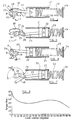
- Figures 1 and 2 show a prior art arrangement in a door closer where the closer spindle 10 has a crank part 11 forming a first link. Pivotally connected to the part 11 at one of its ends is a short second link 12.
- the closer spring 13 has its end nearest the spindle held against a stop 14, its other end being engaged by a piston 15 slidable in a cylindrical housing, the piston being centrally grooved for reception of an appropriate seal (not shown).
- a third, relatively long link 16 is pivotally connected at one end to the piston, extends through the coiled compression spring 13, and has its other end pivotally connected to the other end of the second link 12.
- a fourth link 17 has one of its ends pivotally secured to the closer body at a position below the position of the spindle axis and between said axis and the stop 14, as viewed in Figures 1 and 2.
- the other end of the fourth link is pivotally connected at the pivotal connection of the second and third links, marked 'A' in the figures.
- the pivotal connection of the first and second links is marked 'B' and the pivot of the fourth link to the closer body marked 'C'.
- the fourth link is longer than the second link and angular movement of this link guides the common pivot of the second and third links in an arcuate path when the spindle moves angularly.
- Figure 1 shows the positions of the four links when the door is in its closed position and the spring 13 is in its relaxed state.
- the closer spindle is moved angularly by the external door closer linkage and the link 12 is pulled around anti-clockwise with the part 11.
- This movement of the link 12 effectively pulls the link 16 generally axially of the housing thereby pulling the piston 15 towards the stop 14 and compressing the spring.
- connection 'A' moves along an arc of the circle centred at 'C' and having a radius equal to the distance AC.
- connection 'B' similarly moves along an arc of the circle centred on the closer spindle, and having a radius equal to the distance from the axis of the spindle to connection 'B'.
- Figure 3 is a graph showing torque plotted against spindle rotation for the arrangement of Figures 1 and 2.
- the torque profile is for the closer itself, the actual torque produced at the door being modified by the external linkage.
- the angles shown can effectively be regarded as degrees of door opening.
- GB-A-842988 discloses a further prior art door closer of the general form shown in Figures 1 and 2, with its closer spindle having a cam disc thereon, to which disc is pivotally connected one end of a guide link, the other end of which is pivotally connected to a piston rod of a hydraulic braking device.
- a rocking lever is connected to a fixed hinge pin of the closer housing, and this lever is pivotally connected to the guide link at a position between its ends, one end of a door closer spring assembly also being articulated to the guide link at said position between its ends.
- Such a closer provides a torque profile generally of the required form.
- a device for controlling the movement of a wing comprising a housing, resilient means in the housing, an operating spindle at least partly in the housing and having an axis of rotation, a piston reciprocally movable in one direction under the influence of said resilient means and in the opposite direction upon rotation of said spindle about its axis of rotation upon opening movement of the wing, and a linkage mechanism between said axis and the piston, part of the linkage mechanism being constrained to move along a predetermined path upon rotation of said spindle, so that greater torque is exerted at said operating spindle when the resilient means is in its least or substantially least energy storing state, corresponding to a closed or near closed position of the wing, than when the resilient means is in a state in which it stores energy, corresponding to an open position of the wing, characterised in that said part of the linkage mechanism is constrained to move along said predetermined path by the movement along a cam track of a cam follower carried by the linkage mechanism.
- the linkage mechanism comprises a first link angularly movable about said axis, a second link pivotally connected to the piston, and a third link having spaced pivotal connections to said first and second links respectively, the connection of said second and third links being constrained to move along said predetermined path upon angular movement of said first link.
- said predetermined path has at least a portion of arcuate form with the centre of curvature thereof lying outside said housing.
- connection is constrained to move along a single arc.
- a kit of parts according to the invention comprises a device of the invention as hereinbefore defined together with an arm mechanism connectible at one of its ends to said operating spindle for angular movement about said axis, and a guide rail with which the other end of the arm mechanism engages.
- the present invention provides a device for controlling the movement of a wing, particularly in the form of a door closer, which does provide the torque characteristics desired.
- Figures 4 and 5 which, like Figures 1 and 2 show the arrangement of the links of the linkage mechanism within the door closer at the door closed and door opened positions respectively.
- FIG. 4 and 5 there is a operating spindle 18 arranged, as will be described, to be mounted in a housing of the closer for angular movement about an axis 19 defined thereby.
- the spindle has an integral crank part 20 mid-way between its ends, this part 20 extending generally radially from the axis of the spindle and constituting a first link.
- the embodiment of the invention shown in Figures 4 and 5 has a cylindrical housing 21 within which is reciprocally movable a piston 22 which is in engagement with resilient means in the form of a coiled compression spring 23.
- a double-armed third link 26 Pivotally connected to the end of the crank part away from the spindle 18 is a double-armed third link 26, the two arms being aligned one above the other at opposite sides of the crank part with a pivot pin therethrough, this constituting the pivot 'B' shown in Figures 4 and 5.
- the arms engage at respective opposite sides of the end of the link 25 remote from the piston.
- a cylindrical pivot pin 27 Passing through this connection of the link 25 to the link 26 is a cylindrical pivot pin 27 on the opposite ends of which are respective circular cam followers 28, 29 with internal bearings. Bearings are also provided for the spindle 18 to move angularly in the housing.
- cam tracks 30, 31 respectively, ( Figures 9-12), provided in respective side cheeks forming part of the housing.
- cam track 30 is arcuate, being part of a circle centred at the point 'C' which, in this embodiment, and as viewed in Figures 4 and 5, is below the axis of the spindle 18 on a line therethrough normal to the axis of the housing 21.
- the radius of the circle of which the cam track is part is of a length such that the majority of the cam track is at the side of the spindle axis away from the centre 'C', and moreover the section of the arc provided for the cam tracks is not symmetrical about the vertical line through the centre 'C' and the axis of the spindle, but extends to a greater extent to the right of this line, namely towards the cylindrical housing 21.
- the path through which the cam followers are guided need not be a single arc.
- It can be any continuous curve, the instantaneous centre of curvature of which can be chosen to allow optimisation of the torque profile, and, for example, could have two or more sections of different radii respectively so as to 'fine tune' the torque characteristics.
- Use can be made of the ability to 'tune' the output torque profile by varying the cam track from a circular arc.
- the basic mechanism geometry, as described, provides a basis by giving a sharp rise in torque at closing.
- the cam track can then be 'tuned' to optimise the torque profile.
- An example of such tuning is described hereinafter with reference to Figures 13 to 16 where the position of the centre 'C' and the length of the radius taken from 'C' are varied.
- the cam profile is the path which the centre line of a cam follower describes.
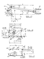
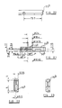
- Figures 9 to 12 show constructional features of the embodiment of Figures 4 and 5 in more detail, with the numerals used in those figures also being used in Figures 9 to 12.
- the housing for the piston and compression spring is in this embodiment formed with the stop 24 being removable, and having an integral forward extension 32 to opposite sides of which are secured by means of screw holes 33 upper and lower housing parts 34, 35 respectively in the form of cheeks, in which are defined the upper and lower cam tracks 30, 31 respectively.
- These housing parts also serve to journal the spindle 18 as shown in Figure 9.
- a portion of approximate sector shape is cut-away from the centre of the piston in a horizontal plane, as viewed in Figure 9, to allow for movement of this end part of the link 25.
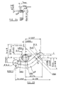
- Figure 12 shows a housing part 34, (housing part 35 being a mirror image), in inside plan view.
- the spindle 18 is connected to one end of a single link arm, the other end of which has a slide portion, such as a slider or roller, engaged in a guide rail, so that as the door is opened and closed this single arm pivots about the spindle 18 whilst simultaneously sliding along the guide rail.
- a slide portion such as a slider or roller
- this form of linkage from the closer to the door or transom/frame is more aesthetically pleasing than previous multi-arm arrangements, such as those of the 'scissors' type and the like, and the link arrangement of the invention is particularly suitable for use with a single external link arm, in that it does not require the use of a relatively long guide rail as previously proposed with single link arm door closers to try to mitigate the poor torque/rotation profile.
- FIG. 6 and 7 A further closer device shown in Figures 6 and 7 is of similar form to that shown in Figures 4 and 5 and like numerals have thus been used for equivalent parts.
- the device of Figures 6 and 7 does not form part of, and is not constructed in accordance with, the present invention in that instead of cam followers and associated cam tracks used in the embodiment previously described, the guiding here of the pivot pin 'A' is provided by a fourth link 48.
- This link in effect, a physical connection between the point 'C' shown in the embodiment of Figures 4 and 5 and the common pivot point 'A' between the links 25 and 26.
- the link 48 can have the same centre as the centre 'C' (but limited to being in the housing) with the distance AC the same as the equivalent distance in the earlier described embodiment. It will thus be appreciated that again the point 'A' will follow an arcuate path of movement upon angular movement of the spindle between the door closed and fully opened positions respectively.
- Figure 8 shows, for the device of Figures 6 and 7, a graph which is a plot of torque at the operating spindle against spindle (crank) rotation, and can thus be compared with the graph shown in Figure 3.
- this graph will be identical for the mechanisms of Figures 4 and 5 and Figures 6 and 7 respectively and it can be seen that there is an initial large torque requirement at the crank rest position (door closed), this then falling continually as the door is opened and the crank moves angularly up to approximately 60°. Thereafter there is a slight increase in torque, until there is a further falling off from approximately 140° of crank angular movement onwards, with it being shown from Figure 7, and also from Figure 8, that 190° of crank angular movement can be obtained.
- the closer it is desirable for the closer to use a single link arm engaging with a guide rail rather than a multi-link arm arrangement.
- the torque profile of Figure 8 is for the closer itself, the actual torque produced at a door, and the door opening angle, being further modified by the external linkage. As stated, the profile is best reproduced by the use of a single link arm.
- Figures 13 to 16 relate to a still further embodiment of the invention in which the cam track of the first embodiment of Figures 4 and 5 is fine tuned as earlier mentioned.
- equivalent parts are similarly numbered, with the addition of the suffix 'a'.
- Figure 13 is a view of the door closer of this still further embodiment in a similar form to that shown in Figure 10.
- the linkages are relatively positioned slightly differently in this 'door closed' position and, more importantly, it can be seen that the cam track in each cheek forming part of opposite sides of the body is no longer a simple circular arc.
- the cam track 30a is made up of a series of points using differing radii of curvature and differently positioned centres, with a curve being constructed between the points.
- An alternative way of regarding the profile is that it made up of a series of arcs of different curvature and centres.
- Figures 13 and 14 include dimensions in mm for the links and the cheek (and thus for this end part of the housing), whilst Table 1 gives values for the X and Y co-ordinates of the centre line of the cam track, the origin for the co-ordinate data being at the axis 19a of spindle 18a. Table 2 gives values of the co-ordinates for the instantaneous centres of curvature and radii of curvature for the centre line of the cam track of Table 1, i.e. for each of the series of points (arcs) making up the track.
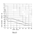
- Figure 16 is a graph of door closing moment against door opening angle for this still further embodiment, and it can be seen that when the cam tracks are 'tuned' the closing moment or torque more closely approaches the ideal requirement for the whole of the door opening movement, up to, in this example, over 180°.
- the fall after initial opening of 2° is much steeper and that from about 10° to 90° of door opening the moment is almost constant, before thereafter reducing at 100° of opening and then remaining substantially constant to maximum door opening.
- the two curves are different in principle because the Figure 16 curve depends upon the geometry of the external links and the mounting on the door, whereas the Figure 8 curve is a property of the closer alone.
- the external links alter not just the torque but also the opening angle. Thus at 190° crank rotation the door may have opened through less than 180°.
- Figure 17 is a diagram showing the link geometry for a crank slider mechanism moving along a portion of a cam track defined by an arc of circle radius R. In other words it represents the geometry of the arrangement of Figures 4 and 5.
- the crank part 20 has a length l 1 , with the link 25 having a length l 3 and the link 26 having a length l 2 .
- the angle which the link 25 makes with the line along which the crank slider moves is denoted by ⁇ , whilst the distance in a line parallel to said line between axis 19 and the pivot of link 25 to the piston slider 22 is x.
- a line is shown through axis 19 parallel to the line along which the crank slider moves, and the angle of crank part 20 to that line is denoted by ⁇ .
- the angle of link 26 to a line through point B parallel to the crank slider line of movement is denoted by ⁇ .
- Figures 18 to 24 show an alternative form of the fine-tuned cam track of Figures 13 to 15. Like Figures 14 and 15, dimensions in mm. are included for the lower cheek 35b, with the corresponding upper cheek being a mirror image. As compared to upper cheek 34a of Figures 13 to 15, lower cheek 35b has equivalent parts similarly numbered, but with suffix 'b'.
- Figure 25 is an enlarged view of the fine-tuned cam track 30b. This can be regarded as made up of a series of values defining the centre line of the cam track, with the origin for the co-ordinate data being at the axis 19b of spindle 18b. Selected values are set out in Table 3, in the same way as for Table 1.
- the cam track 30b can also, however, in a simplified form, be regarded as being reduced to a series of radii, as shown in Figure 25, which includes typical values of radii, as well as other dimensions for this particular example. The centres about which the respective arcs are struck are also shown.
- a part-circular left hand end of the track merges to a first part defined by an arc 'a'. There then follows a second part defined by an arc 'b' which is joined to a third arc 'c' by a straight line, which is in fact tangential. There is then a fourth arc 'd' joined by a further tangential straight line to the third arc 'c', and the centre line of the cam track is completed by fifth and sixth arcs 'e' and 'f' respectively.
- the right hand end of the track is part-circular, but has a local relief to assist assembly, in use, of the follower.
- Figure 26 shows two plots of door movement torque against door movement angle for a door closer of the invention incorporating a pair of cheeks each having the cam track of Figures 18 to 25.
- the upper graph corresponds to door opening and the lower graph corresponds to door closing, the difference being attributable to hysteresis loss.
- Figure 27 shows how, at least as an approximation, two interlinked parabolic curves can be fitted to the closing graph of Figure 26 from the maximum torque position at 2° to approximately 30° of door movement, the first curve 'A' opening downwardly and the second curve 'B' opening upwardly.
- the torque profiles shown in Figure 26 are believed to be almost the optimum and to represent an improvement over those of known door closer devices in two aspects, namely:
- Figures 28 to 32 show various possible arrangements for mounting a device of the present invention at a door and associated transom (frame).
- FIG 28 there is shown a door 49 with associated transom 50, a device of the invention being shown at 51 having a single slide arm 52 which engages in a guide rail 53.
- the device 51 is mounted on the pull side of the door with the door being hinged to the transom in a standard manor.
- torque the moment
- 29 Nm the moment at 90° of opening the moment is 29 Nm.
- the embodiment shown in Figure 29 is similar to that shown in Figure 28 but uses an offset hinge arrangement.
- the equivalent moments are 54 Nm and 36 Nm respectively.
- the device 51 is mounted on the transom at the pull side of the door and standard hinges are used as with the arrangement shown in Figure 28.
- the moment at 2° of opening is 69 Nm and at 90° of opening is 36 Nm.
- Figure 31 shows an arrangement where the device 51 is transom mounted at the push side of the door, with a maximum opening of 100°.
- the moment at 2° of opening is 34 Nm with a value of 13 Nm at 90° of opening.
- the device 51 is door mounted at the push side thereof, with a maximum opening of 130°.
- the moment 2° of opening is 60 Nm and 45 Nm at 90° of opening. All these quoted moment values are approximate and may vary within the range of experimental error.
- the transom mounted arrangement can give the same initial torque as the Figure 28 application, but thereafter the geometry will change the torque profile. They do however illustrate the desired fall-off in force needed to move the door through ninety degrees.
- the present invention also relates to such a device together with an arm mechanism in the form of a single slide arm, connectable at one end to the housing for angular movement about the axis defined in the housing and having a slide portion (slide, roller or the like) at its other end, and a guide rail with which the slide portion of the single slide arm engages.
- an arm mechanism in the form of a single slide arm, connectable at one end to the housing for angular movement about the axis defined in the housing and having a slide portion (slide, roller or the like) at its other end, and a guide rail with which the slide portion of the single slide arm engages.
- a kit of parts would thus be sold comprising the device, the slide arm and the guide rail together with appropriate ancillary fixing means.
- the device of the invention is also applicable for use with a floor spring for controlling the movement of a wing, for example a door.
- Suitable equivalent resilient means can be used in any versions of devices of the invention instead of a compression spring, for example a bag containing compressible gas.
- a pair of spaced cheeks each having the cam track therein there could be a single cam follower in a single cam track in a single central housing part, the cam follower projecting to opposite sides of the single part where it is connected by respective link arms to the door closer spindle and also to the piston.
Landscapes
- Closing And Opening Devices For Wings, And Checks For Wings (AREA)
- Toys (AREA)
- Structures Of Non-Positive Displacement Pumps (AREA)
- Power-Operated Mechanisms For Wings (AREA)
- Transmission Devices (AREA)
Claims (17)
- Dispositif de commande de déplacement d'un battant, comprenant un boítier, un moyen élastique (23) dans le boítier, une broche de travail (18) située au moins partiellement dans le boítier et ayant un axe de rotation, un piston (22) pouvant effectuer un mouvement réciproque dans une direction sous l'influence dudit moyen élastique et dans la direction opposée sous l'effet de la rotation de ladite broche autour de son axe de rotation lors du mouvement d'ouverture du battant, et un mécanisme de liaison (20, 25, 26) entre ledit axe et le piston, une partie du mécanisme de liaison étant contrainte de se déplacer le long d'un trajet prédéterminé lors de la rotation de ladite broche, de manière à ce qu'un couple plus grand soit exercé au niveau de ladite broche de travail lorsque le moyen élastique se trouve dans l'état où il accumule le moins d'énergie ou effectivement très peu d'énergie, correspondant au battant en position fermée ou presque fermée, que lorsque le moyen élastique se trouve dans un état où il accumule de l'énergie, correspondant au battant en position ouverte, caractérisé en ce que ladite partie du mécanisme de liaison est contrainte de se déplacer le long dudit trajet prédéterminé à cause du déplacement, le long d'un guide de came (30, 31), d'un galet de came (28, 29) porté par le mécanisme de liaison.
- Dispositif selon la revendication 1, dans lequel le mécanisme de liaison comprend un premier élément d'articulation (20) pouvant se déplacer de façon angulaire autour dudit axe, un second élément d'articulation (25) relié de façon pivotante au piston (22) et un troisième élément d'articulation (26) ayant des raccords pivotants espacés le reliant aux dits premier et second éléments d'articulation, respectivement, le raccord desdits second et troisième éléments d'articulation étant contraint de se déplacer le long dudit trajet prédéterminé lors du déplacement angulaire dudit premier élément d'articulation.
- Dispositif selon la revendication 2, dans lequel ledit troisième élément d'articulation (26) est relié, à ses extrémités opposées respectives, aux dits premier et second éléments d'articulation.
- Dispositif selon la revendication 2 ou la revendication 3, dans lequel ledit trajet prédéterminé a la forme d'une courbe continue.
- Dispositif selon la revendication 4, dans lequel le centre de courbure d'au moins une partie de ladite courbe est situé à l'extérieur dudit boítier.
- Dispositif selon la revendication 4, dans lequel ladite courbe est un arc unique.
- Dispositif selon la revendication 6, dans lequel le centre de courbure dudit arc unique est situé à l'extérieur du boítier.
- Dispositif selon l'une quelconque des revendications 2 à 7, dans lequel les extrémités opposées respectives de ladite broche de travail (18) sont tourillonnées dans deux parties de boítier (34, 35) situées à distance l'une de l'autre, qui sont pourvues, dans leurs surfaces internes respectives se faisant face, de guides de came (30, 31) dont la forme et la position sont identiques.
- Dispositif selon la revendication 8, dans lequel ledit premier élément d'articulation (20) est défini par une partie de bielle de ladite broche de travail (18), deux bras formant ledit troisième élément d'articulation (26) sont disposés sur les côtés opposés respectifs de ladite partie de bielle et reliés l'un à l'autre de façon pivotante au niveau de ladite partie de bielle, un pivot (27) traverse lesdits bras et la partie dudit second élément d'articulation (25) qui est située entre les deux, et des galets de came (28, 29) portés par les extrémités opposées respectives du pivot sont reçus, respectivement, dans lesdits guides de came (30, 31) dans lesdites surfaces internes des parties de boítier (34, 35).
- Dispositif selon l'une quelconque des revendications 2 à 9, dans lequel le second élément d'articulation (25) est relié de façon pivotante au piston (22) à l'une de ses extrémités.
- Dispositif selon la revendication 10, dans lequel le piston (22) est pourvu d'un évidement cintré au niveau de la position de son raccord pivotant avec le second élément d'articulation (25) de manière à permettre le déplacement angulaire dudit second élément d'articulation.
- Dispositif selon l'une quelconque des revendications précédentes, dans lequel le moyen élastique (23) est adapté pour agir sur une extrémité du piston (22) opposée à l'extrémité depuis laquelle s'étend ledit second élément d'articulation (25).
- Dispositif selon la revendication 12, dans lequel le moyen élastique (23) agit entre ledit piston mobile et un élément d'arrêt d'extrémité (24) du boítier.
- Dispositif selon l'une quelconque des revendications précédentes, dans lequel ledit moyen élastique (22) est un ressort de pression.
- Dispositif selon l'une quelconque des revendications précédentes, dans lequel le couple maximum exercé au niveau de ladite broche de travail (18) l'est lorsque le battant est presque fermé.
- Ensemble de pièces comprenant un dispositif selon l'une quelconque des revendications précédentes, un mécanisme à bras (52) pouvant être connecté, à l'une de ses extrémités, à ladite broche de travail (18) d'une manière permettant un déplacement angulaire autour dudit axe, et un rail de guidage (53) avec lequel l'autre extrémité du mécanisme à bras est en prise.
- Ensemble de pièces selon la revendication 16, dans lequel le mécanisme à bras se présente sous la forme d'un bras d'articulation unique (52).
Applications Claiming Priority (3)
| Application Number | Priority Date | Filing Date | Title |
|---|---|---|---|
| GB939325906A GB9325906D0 (en) | 1993-12-17 | 1993-12-17 | Device for controlling the movement of a wing |
| GB9325906 | 1993-12-17 | ||
| PCT/GB1994/002668 WO1995016845A1 (fr) | 1993-12-17 | 1994-12-06 | Dispositif de commande de deplacement d'un battant |
Publications (2)
| Publication Number | Publication Date |
|---|---|
| EP0734484A1 EP0734484A1 (fr) | 1996-10-02 |
| EP0734484B1 true EP0734484B1 (fr) | 1998-08-05 |
Family
ID=10746831
Family Applications (1)
| Application Number | Title | Priority Date | Filing Date |
|---|---|---|---|
| EP95902858A Expired - Lifetime EP0734484B1 (fr) | 1993-12-17 | 1994-12-06 | Dispositif de commande de deplacement d'un battant |
Country Status (8)
| Country | Link |
|---|---|
| US (1) | US5680674A (fr) |
| EP (1) | EP0734484B1 (fr) |
| AT (1) | ATE169367T1 (fr) |
| AU (1) | AU680326B2 (fr) |
| DE (1) | DE69412285T2 (fr) |
| GB (1) | GB9325906D0 (fr) |
| NZ (1) | NZ277062A (fr) |
| WO (1) | WO1995016845A1 (fr) |
Families Citing this family (15)
| Publication number | Priority date | Publication date | Assignee | Title |
|---|---|---|---|---|
| US6481160B1 (en) * | 1999-02-04 | 2002-11-19 | The Stanley Works | Axial door operator |
| ATE331112T1 (de) | 1999-02-04 | 2006-07-15 | Stanley Works | Automatiktüranordnung und automatischer türbetätiger dafür |
| WO2001027491A2 (fr) * | 1999-10-08 | 2001-04-19 | Intellect Highway Limited | Ameliorations concernant une unite comprenant un element mobile |
| JP3363897B2 (ja) * | 2001-01-23 | 2003-01-08 | 精工技研株式会社 | トラック等のウイング開閉装置 |
| US8225458B1 (en) | 2001-07-13 | 2012-07-24 | Hoffberg Steven M | Intelligent door restraint |
| DE102004007491B4 (de) * | 2004-02-13 | 2006-12-21 | Johnson Controls Gmbh | Vorrichtung mit einem Aktuator, insbesondere an einem Beschlag zur Verstellung von Teilen eines Fahrzeugssitzes |
| DE102004061619C5 (de) * | 2004-12-17 | 2011-09-29 | Dorma Gmbh + Co. Kg | Türantrieb, insbesondere Drehtürantrieb |
| KR100823139B1 (ko) * | 2006-12-29 | 2008-04-21 | (주) 아이레보 금강씨에스 | 제연구역 내 방화문의 도어클로저 닫힘보조장치 |
| KR100888724B1 (ko) | 2007-12-27 | 2009-03-25 | (주) 아이레보 금강씨에스 | 도어 클로저의 부가적 폐쇄력 제공장치 |
| DE102013112453A1 (de) * | 2013-11-13 | 2015-05-13 | Dorma Deutschland Gmbh | Obentürschließer |
| US10487923B2 (en) * | 2017-09-14 | 2019-11-26 | Whippany Actuation Systems Llc | Multi-bar linkage mechanism |
| ES3023065T3 (en) * | 2019-04-19 | 2025-05-29 | Cisaplast S P A | Hinge for doors of refrigerated cabinets |
| EP4177431A1 (fr) * | 2021-11-04 | 2023-05-10 | EBm Konstruktioner AB | Module pour le transfert d'un mouvement de rotation à un élément ouvrable et fermable et système comprenant le module |
| WO2023156893A1 (fr) * | 2022-02-18 | 2023-08-24 | In & Tec S.R.L. | Charnière pour portes ou volets oscillants, en particulier pour armoires réfrigérées, ainsi que système comprenant ladite charnière |
| IT202200003044A1 (it) * | 2022-02-18 | 2023-08-18 | In & Tec Srl | Cerniera per porte o ante a battente, in particolare per banchi frigo |
Family Cites Families (13)
| Publication number | Priority date | Publication date | Assignee | Title |
|---|---|---|---|---|
| US1957308A (en) * | 1932-04-23 | 1934-05-01 | Hart & Hutchinson Company | Door closer and check |
| US2653043A (en) * | 1951-03-19 | 1953-09-22 | Boyd N Carlson | Door closer |
| GB842988A (en) * | 1955-10-18 | 1960-08-04 | Ver Baubeschlag Gretsch Co | Improvements in or relating to door-closing devices |
| BE594592A (fr) * | 1959-09-05 | 1960-12-16 | Ver Baubeschlag Gretsch Co | Fermeture, en particulier pour portes battantes |
| US3398434A (en) * | 1965-12-07 | 1968-08-27 | Formex Mfg Inc | Vacuum forming apparatus |
| GB1207841A (en) * | 1967-08-05 | 1970-10-07 | John Brown | A new or improved door closer |
| DE2243475A1 (de) * | 1972-09-05 | 1974-03-14 | Ver Baubeschlag Gretsch Co | Bodentuerschliesser |
| DE2258583A1 (de) * | 1972-11-30 | 1974-06-06 | Ver Baubeschlag Gretsch Co | Bodentuerschliesser |
| US3950819A (en) * | 1975-01-16 | 1976-04-20 | Weber-Knapp Company | Lid counter-balance mechanism |
| DE3427609A1 (de) * | 1984-07-26 | 1986-02-06 | Ryobi Ltd., Fuchu, Hiroshima | Vorrichtung zum schliessen einer feuersicheren tuer |
| US4763385A (en) * | 1985-07-05 | 1988-08-16 | Geze Gmbh | Door closure transmission utilizing an eccentric pinion |
| DE3524185A1 (de) * | 1985-07-05 | 1987-01-15 | Geze Gmbh | Tuerschliesser |
| US4788742A (en) * | 1987-12-17 | 1988-12-06 | Door Control Specialties Co. | Torque modification apparatus for use with a door closer |
-
1993
- 1993-12-17 GB GB939325906A patent/GB9325906D0/en active Pending
-
1994
- 1994-12-06 AT AT95902858T patent/ATE169367T1/de not_active IP Right Cessation
- 1994-12-06 US US08/628,693 patent/US5680674A/en not_active Expired - Lifetime
- 1994-12-06 AU AU11952/95A patent/AU680326B2/en not_active Expired
- 1994-12-06 EP EP95902858A patent/EP0734484B1/fr not_active Expired - Lifetime
- 1994-12-06 DE DE69412285T patent/DE69412285T2/de not_active Expired - Lifetime
- 1994-12-06 WO PCT/GB1994/002668 patent/WO1995016845A1/fr not_active Ceased
- 1994-12-06 NZ NZ277062A patent/NZ277062A/en not_active IP Right Cessation
Also Published As
| Publication number | Publication date |
|---|---|
| EP0734484A1 (fr) | 1996-10-02 |
| DE69412285T2 (de) | 1999-04-08 |
| GB9325906D0 (en) | 1994-02-23 |
| DE69412285D1 (de) | 1998-09-10 |
| AU1195295A (en) | 1995-07-03 |
| NZ277062A (en) | 1996-09-25 |
| US5680674A (en) | 1997-10-28 |
| AU680326B2 (en) | 1997-07-24 |
| WO1995016845A1 (fr) | 1995-06-22 |
| ATE169367T1 (de) | 1998-08-15 |
Similar Documents
| Publication | Publication Date | Title |
|---|---|---|
| EP0734484B1 (fr) | Dispositif de commande de deplacement d'un battant | |
| US4744125A (en) | Door closer transmission including an eccentric pinion | |
| US5058238A (en) | Crosslink hinge with closing mechanism | |
| EP1995524B1 (fr) | Charnière pour ailes ou portes | |
| US7562416B2 (en) | Damping device with a joint hinge | |
| JP4787252B2 (ja) | 旋回可能なように取り付けた駆動アーム用の駆動機構 | |
| EP0693156B1 (fr) | Ensemble porte a equilibrage renforce | |
| US5333920A (en) | Panel for closing an opening, and clip system for use as a part thereof | |
| US4128120A (en) | Tambour door and housing assembly | |
| CN105683474A (zh) | 用于提供来自闭门器或操作器的恒定的扭矩输出的设备 | |
| AU2021354729A1 (en) | Multi-joint hinge | |
| GB2278882A (en) | Concealed door closer | |
| AU2018255813B2 (en) | Pivot drive and piece of furniture | |
| US4372005A (en) | Operator for sliding doors | |
| TW202221216A (zh) | 帶有用於運動控制設備的驅動裝置的傢俱鉸鏈 | |
| EP0856628B1 (fr) | Ferme-porte | |
| JP7183220B2 (ja) | 下降窓開閉補助具 | |
| TW202221215A (zh) | 用於傢俱的不可見鉸鏈 | |
| TW202221217A (zh) | 用於傢俱的鉸鏈 | |
| AU2018255730B2 (en) | Mechanism for moving a furniture door | |
| US4457047A (en) | Over-center self-closing hinge having a spring biased cam thruster | |
| WO2010082028A1 (fr) | Ensembles charnière amortis | |
| CN219864634U (zh) | 双门同步开合联动结构及采用该结构的自动双开门烤箱 | |
| US20180252015A1 (en) | Door closing device with multi-ratio rack and pinion | |
| CN110313735B (zh) | 一种用于家具的按压反弹开闭优化结构 |
Legal Events
| Date | Code | Title | Description |
|---|---|---|---|
| PUAI | Public reference made under article 153(3) epc to a published international application that has entered the european phase |
Free format text: ORIGINAL CODE: 0009012 |
|
| 17P | Request for examination filed |
Effective date: 19960409 |
|
| AK | Designated contracting states |
Kind code of ref document: A1 Designated state(s): AT BE CH DE DK ES FR GB IE IT LI LU NL PT SE |
|
| 17Q | First examination report despatched |
Effective date: 19961223 |
|
| GRAG | Despatch of communication of intention to grant |
Free format text: ORIGINAL CODE: EPIDOS AGRA |
|
| GRAG | Despatch of communication of intention to grant |
Free format text: ORIGINAL CODE: EPIDOS AGRA |
|
| GRAH | Despatch of communication of intention to grant a patent |
Free format text: ORIGINAL CODE: EPIDOS IGRA |
|
| GRAH | Despatch of communication of intention to grant a patent |
Free format text: ORIGINAL CODE: EPIDOS IGRA |
|
| GRAA | (expected) grant |
Free format text: ORIGINAL CODE: 0009210 |
|
| AK | Designated contracting states |
Kind code of ref document: B1 Designated state(s): AT BE CH DE DK ES FR GB IE IT LI LU NL PT SE |
|
| PG25 | Lapsed in a contracting state [announced via postgrant information from national office to epo] |
Ref country code: LI Free format text: LAPSE BECAUSE OF FAILURE TO SUBMIT A TRANSLATION OF THE DESCRIPTION OR TO PAY THE FEE WITHIN THE PRESCRIBED TIME-LIMIT Effective date: 19980805 Ref country code: IT Free format text: LAPSE BECAUSE OF FAILURE TO SUBMIT A TRANSLATION OF THE DESCRIPTION OR TO PAY THE FEE WITHIN THE PRESCRIBED TIME-LIMIT;WARNING: LAPSES OF ITALIAN PATENTS WITH EFFECTIVE DATE BEFORE 2007 MAY HAVE OCCURRED AT ANY TIME BEFORE 2007. THE CORRECT EFFECTIVE DATE MAY BE DIFFERENT FROM THE ONE RECORDED. Effective date: 19980805 Ref country code: ES Free format text: THE PATENT HAS BEEN ANNULLED BY A DECISION OF A NATIONAL AUTHORITY Effective date: 19980805 Ref country code: CH Free format text: LAPSE BECAUSE OF FAILURE TO SUBMIT A TRANSLATION OF THE DESCRIPTION OR TO PAY THE FEE WITHIN THE PRESCRIBED TIME-LIMIT Effective date: 19980805 Ref country code: AT Free format text: LAPSE BECAUSE OF FAILURE TO SUBMIT A TRANSLATION OF THE DESCRIPTION OR TO PAY THE FEE WITHIN THE PRESCRIBED TIME-LIMIT Effective date: 19980805 |
|
| REF | Corresponds to: |
Ref document number: 169367 Country of ref document: AT Date of ref document: 19980815 Kind code of ref document: T |
|
| REG | Reference to a national code |
Ref country code: CH Ref legal event code: EP |
|
| REF | Corresponds to: |
Ref document number: 69412285 Country of ref document: DE Date of ref document: 19980910 |
|
| REG | Reference to a national code |
Ref country code: IE Ref legal event code: FG4D |
|
| PG25 | Lapsed in a contracting state [announced via postgrant information from national office to epo] |
Ref country code: SE Free format text: LAPSE BECAUSE OF FAILURE TO SUBMIT A TRANSLATION OF THE DESCRIPTION OR TO PAY THE FEE WITHIN THE PRESCRIBED TIME-LIMIT Effective date: 19981105 Ref country code: PT Free format text: LAPSE BECAUSE OF FAILURE TO SUBMIT A TRANSLATION OF THE DESCRIPTION OR TO PAY THE FEE WITHIN THE PRESCRIBED TIME-LIMIT Effective date: 19981105 Ref country code: DK Free format text: LAPSE BECAUSE OF FAILURE TO SUBMIT A TRANSLATION OF THE DESCRIPTION OR TO PAY THE FEE WITHIN THE PRESCRIBED TIME-LIMIT Effective date: 19981105 |
|
| ET | Fr: translation filed | ||
| PG25 | Lapsed in a contracting state [announced via postgrant information from national office to epo] |
Ref country code: LU Free format text: LAPSE BECAUSE OF NON-PAYMENT OF DUE FEES Effective date: 19981206 Ref country code: IE Free format text: LAPSE BECAUSE OF NON-PAYMENT OF DUE FEES Effective date: 19981206 |
|
| REG | Reference to a national code |
Ref country code: CH Ref legal event code: PL |
|
| PLBE | No opposition filed within time limit |
Free format text: ORIGINAL CODE: 0009261 |
|
| STAA | Information on the status of an ep patent application or granted ep patent |
Free format text: STATUS: NO OPPOSITION FILED WITHIN TIME LIMIT |
|
| 26N | No opposition filed | ||
| REG | Reference to a national code |
Ref country code: IE Ref legal event code: MM4A |
|
| REG | Reference to a national code |
Ref country code: GB Ref legal event code: IF02 |
|
| REG | Reference to a national code |
Ref country code: GB Ref legal event code: 732E |
|
| BECA | Be: change of holder's address |
Owner name: *IR SECURITY & SAFETY LTDBESCOT CRESCENT, WALSALL, Effective date: 20031126 |
|
| BECN | Be: change of holder's name |
Owner name: *IR SECURITY & SAFETY LTD Effective date: 20031126 |
|
| NLS | Nl: assignments of ep-patents |
Owner name: INGERSOLL-RAND ARCHITECTURAL HARDWARE GROUP LIMITE |
|
| NLT1 | Nl: modifications of names registered in virtue of documents presented to the patent office pursuant to art. 16 a, paragraph 1 |
Owner name: IR SECURITY & SAFETY LIMITED |
|
| REG | Reference to a national code |
Ref country code: FR Ref legal event code: TP Ref country code: FR Ref legal event code: CD Ref country code: FR Ref legal event code: CA |
|
| PGFP | Annual fee paid to national office [announced via postgrant information from national office to epo] |
Ref country code: GB Payment date: 20131125 Year of fee payment: 20 Ref country code: DE Payment date: 20131121 Year of fee payment: 20 |
|
| PGFP | Annual fee paid to national office [announced via postgrant information from national office to epo] |
Ref country code: NL Payment date: 20131122 Year of fee payment: 20 Ref country code: BE Payment date: 20131121 Year of fee payment: 20 |
|
| PGFP | Annual fee paid to national office [announced via postgrant information from national office to epo] |
Ref country code: FR Payment date: 20131219 Year of fee payment: 20 |
|
| REG | Reference to a national code |
Ref country code: DE Ref legal event code: R071 Ref document number: 69412285 Country of ref document: DE |
|
| REG | Reference to a national code |
Ref country code: NL Ref legal event code: V4 Effective date: 20141206 |
|
| REG | Reference to a national code |
Ref country code: GB Ref legal event code: PE20 Expiry date: 20141205 |
|
| PG25 | Lapsed in a contracting state [announced via postgrant information from national office to epo] |
Ref country code: GB Free format text: LAPSE BECAUSE OF EXPIRATION OF PROTECTION Effective date: 20141205 |