EP0734751B1 - Séparateur à cyclone ayant un coalesceur incorporé - Google Patents
Séparateur à cyclone ayant un coalesceur incorporé Download PDFInfo
- Publication number
- EP0734751B1 EP0734751B1 EP96400638A EP96400638A EP0734751B1 EP 0734751 B1 EP0734751 B1 EP 0734751B1 EP 96400638 A EP96400638 A EP 96400638A EP 96400638 A EP96400638 A EP 96400638A EP 0734751 B1 EP0734751 B1 EP 0734751B1
- Authority
- EP
- European Patent Office
- Prior art keywords
- separators
- cyclone
- tubular element
- separator
- tubular
- Prior art date
- Legal status (The legal status is an assumption and is not a legal conclusion. Google has not performed a legal analysis and makes no representation as to the accuracy of the status listed.)
- Expired - Lifetime
Links
- 238000004581 coalescence Methods 0.000 title claims description 15
- 239000007788 liquid Substances 0.000 claims abstract description 4
- 239000000839 emulsion Substances 0.000 claims description 26
- 210000004209 hair Anatomy 0.000 claims description 3
- 239000011358 absorbing material Substances 0.000 claims 2
- 239000000463 material Substances 0.000 abstract description 3
- 238000000926 separation method Methods 0.000 abstract 1
- 239000012071 phase Substances 0.000 description 16
- XLYOFNOQVPJJNP-UHFFFAOYSA-N water Substances O XLYOFNOQVPJJNP-UHFFFAOYSA-N 0.000 description 12
- 238000004519 manufacturing process Methods 0.000 description 6
- 239000000203 mixture Substances 0.000 description 5
- 238000011144 upstream manufacturing Methods 0.000 description 5
- 239000004576 sand Substances 0.000 description 4
- -1 for example Substances 0.000 description 2
- 239000011343 solid material Substances 0.000 description 2
- 239000000725 suspension Substances 0.000 description 2
- BSYNRYMUTXBXSQ-UHFFFAOYSA-N Aspirin Chemical compound CC(=O)OC1=CC=CC=C1C(O)=O BSYNRYMUTXBXSQ-UHFFFAOYSA-N 0.000 description 1
- 239000004952 Polyamide Substances 0.000 description 1
- 239000004743 Polypropylene Substances 0.000 description 1
- 150000001875 compounds Chemical class 0.000 description 1
- 230000000694 effects Effects 0.000 description 1
- 238000012423 maintenance Methods 0.000 description 1
- 238000000034 method Methods 0.000 description 1
- 238000013508 migration Methods 0.000 description 1
- 230000005012 migration Effects 0.000 description 1
- 238000005192 partition Methods 0.000 description 1
- JTJMJGYZQZDUJJ-UHFFFAOYSA-N phencyclidine Chemical class C1CCCCN1C1(C=2C=CC=CC=2)CCCCC1 JTJMJGYZQZDUJJ-UHFFFAOYSA-N 0.000 description 1
- 239000004033 plastic Substances 0.000 description 1
- 229920002647 polyamide Polymers 0.000 description 1
- 229920001155 polypropylene Polymers 0.000 description 1
- 238000007789 sealing Methods 0.000 description 1
- 239000007787 solid Substances 0.000 description 1
- 239000007790 solid phase Substances 0.000 description 1
- 239000002351 wastewater Substances 0.000 description 1
Images

Classifications
-
- B—PERFORMING OPERATIONS; TRANSPORTING
- B01—PHYSICAL OR CHEMICAL PROCESSES OR APPARATUS IN GENERAL
- B01D—SEPARATION
- B01D17/00—Separation of liquids, not provided for elsewhere, e.g. by thermal diffusion
- B01D17/02—Separation of non-miscible liquids
- B01D17/0217—Separation of non-miscible liquids by centrifugal force
-
- B—PERFORMING OPERATIONS; TRANSPORTING
- B01—PHYSICAL OR CHEMICAL PROCESSES OR APPARATUS IN GENERAL
- B01D—SEPARATION
- B01D17/00—Separation of liquids, not provided for elsewhere, e.g. by thermal diffusion
- B01D17/02—Separation of non-miscible liquids
- B01D17/04—Breaking emulsions
- B01D17/045—Breaking emulsions with coalescers
Definitions
- the present invention relates to a separator with cyclone having an incorporated coalescer and, more particularly, to such a separator having a coalescer which is capable of constituting for it a stage of upstream pretreatment, as well as a set comprising a plurality of such separators.
- Cyclone separators are generally intended to separate two immiscible phases of different densities.
- this type of separator the mixture of the two phases to be separated is injected at high speed into a chamber which is generally cylindrical in such a way that the mixture progresses through the room with movement roundabout.
- the centrifugal forces generated by this gyratory movement acting on the mixture of the two phases of different densities cause the migration of the denser phase towards the wall of the chamber, the phase lighter remaining towards the interior of the chamber.
- the two phases can be separated.
- the axial outlet of this type of separator generally includes a tubular portion of low taper which is connected to the cylindrical chamber by a conical part.
- Two cyclone separator phases of this type are described in US-A-4,749,490.
- Three-phase cyclone separators suitable for separate a solid phase, for example from sand, which is suspended in a compound emulsion, for example, oil and water are also known. Such three-phase separator is described in US-A-5,332,500. Three-phase cyclones have in common with two-phase separators one output for one of the phases liquids which includes an elongated tubular part of weak taper.
- cyclone separators A main application of cyclone separators is the treatment of wastewater from wells oil and / or gas production.
- cyclone separators are used on platforms oil production maritime to process the oil / water / sand mixture which is separated from the production in order to clean the water before its evacuation or reinjection.
- the space available on a production platform is very limited.
- Many cyclone separators are generally installed next to side in a processing unit located on the platform.
- the shape of the conical parts described previously, and that of the tubular parts of weak taper mean that there is a considerable amount of space lost in the processing unit between different separators.
- this pretreatment stage includes advantageously a coalescer intended to transform the microscopic drops of oil in the emulsion in drops larger which are more easily separated in the cyclone.
- coalescers cannot be used due to the lack of available space.
- US-A-4,116,790 discloses cyclone separators further comprising electrostatic coalescers.
- the electrodes can be arranged on the tangential entry (Figs. 1-3) or else around the entire cyclone (Figs. 4a, 4b).
- the wall of a cylindrical chamber surrounding the cyclone, the part conical cyclone, as well as a conical element surrounding the outlet tubular can constitute electrodes.
- the object of the present invention is therefore to propose a cyclone separator having a coalescer upstream to pre-treat the emulsion to be separated, but which is more compact than the proposed devices previously and therefore reduces the space lost, as well as an assembly comprising a plurality of such separators.
- a separator is proposed. cyclone as defined in claim 1, particular modes being defined in claims 2-4.
- a set of separators comprising a plurality of cyclone separators, as defined in claim 5, particular models being the subject of claims 6-10.
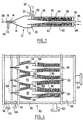
- Figure 1 is a schematic cross-sectional view a cyclone separator having a coalescer incorporated, according to a first variant of the invention
- Figures 2 and 3 are schematic sectional views transverse of separators according to a second and a third variants of the invention.
- FIGS 2a and 3a are detailed views of parts separators of Figures 2 and 3 respectively;
- Figure 4 is a schematic cross-sectional view of a set of separators according to another variant of the invention.
- Figure 1 is a cross-sectional view of a three-phase cyclone separator which includes a body 10 consisting of a cylindrical part 12 and a part conical 14.
- the conical part 14 is provided, at the top of the cone, of a final cylindrical section 16 inside which is arranged a tubular outlet 18, both being located coaxially with the cylindrical part 12.
- the body 10 is closed by an annular element 20 which includes one or more entry (s) 22 for the emulsion to be treated in the cyclone.
- the entrance is arranged tangentially with respect to the cylindrical part 12.
- a generally tubular element 26 which includes a portion of low taper 28 and a cylindrical extension 30.
- An oil / water emulsion containing a solid material suspended enters the body under pressure through entrance 22 in the direction of arrow 32 and take thus a tangential path to the body 10.
- the emulsion flows at high speed in a roundabout movement inside the cylindrical part 12.
- the solid matter in suspension migrates to the walls of the cylindrical part 12 and the conical part 14 and is discharged through the final section 16, in the direction of arrow 34.
- the conical configuration of part 14 strength the oil / water emulsion, from which the solid material was withdrawn, to change its longitudinal direction of flow and to pass through the tubular element 26 while continuing to flow in its gyratory movement.
- the two phases of the emulsion separate during its passage along the portion of weak conicity 28, the water located towards the wall of parts 28 and 30, while the oil moves towards the axis thereof.
- Back pressure caused by a restriction formed to the end of the tubular extension 30 applies to the oil flow and causes it to reverse its direction.
- An oil stream is therefore formed to flow in a direction opposite to that of water, and the oil leaves the separator through the exit 18 in the direction of arrow 36, the water purified leaving tubular extension 30 in the arrow direction 38.
- a coalescer that is to say coalescing means 40, is arranged around and mounted directly on the tubular member 20, substantially the along the entire length of it.
- the coalescer is of the brush type and is composed a large number of hairs, made of oleophilic matter, which generally project radially from the outer wall of the tubular element 20.
- the oleophilic material used is a material plastic such as polyamide or polypropylene.
- a cylindrical sleeve 42 is located around the coalescer and defines with the annular element 20 a chamber of coalescence 44.
- the cylindrical extension 30 projects through an end wall 46 of the cylindrical sleeve 42.
- the cylindrical sleeve 42 includes an inlet 48 and an output 50 which communicates directly with input 22 of the cyclone separator.
- the cylindrical sleeve can be formed by the walls of the container containing the cyclone separator.
- the emulsion to be treated When running, the emulsion to be treated is injected into entrance 48 of coalescence chamber 44 where it progresses along the length of the tubular member 26, touching the oleophilic brushes of the coalescer 40, before leaving the room via exit 50.
- the contact between the emulsion and the oleophilic brushes causes microscopic oil droplets in the emulsion to coalesce and form droplets of which the average diameter has been considerably increased. These droplets remain in suspension in the emulsion when it leaves the coalescing chamber 44 through the exit 50.
- the pretreated emulsion containing the droplets of magnified oil, is then injected into the separator cyclone through entrance 22 where it follows the path described above.
- the diameter mean oil droplets is significantly more large than in an untreated emulsion, the yield of cyclone is significantly increased, the percentage of oil removed from the emulsion being increased by approximately 5 to 20% depending on the characteristics of the emulsion that comes in.
- FIG. 2 A second variant has been shown in Figure 2 a cyclone separator according to the first aspec of the invention in which, for the sake of ease of manufacture and maintenance, the coalescer is constituted as a separate subset which can be mounted on an existing cyclone.
- a cyclone separator 60 which in the example illustrated is a two-phase cyclone, has a set of coalescers, that is to say coalescing means 64, arranged around the tubular element 62, which includes a generally tubular sleeve 66 of which the internal dimensions correspond exactly to external dimensions of the tubular element 62 and of the conical part 68, the coalescing means being mounted on the sleeve.
- the tubular sleeve 66 is more clearly visible in Figure 2a.
- the functioning cyclone and the upstream pretreatment stage constituted by the coalescer is similar to that of the variant of Figure 1.
- FIG. 3 and 3a another variant of cyclone which differs from that of Figures 2 and 2a in that the tubular sleeve on which the brush coalescer has a cross section constant cylindrical.
- a tubular sleeve 70 of cross section constant, is mounted on the cyclone separator 72 between the conical part 74 and an injector 76 at the end of the tubular element 78.
- the functioning of the cyclone and upstream pretreatment coalescer is similar to that of the variants of Figures 1 and 2, the element tubular and coalescer being inserted into a sleeve tubular (not shown), as in the case of the device of Figure 1.
- Figure 4 shows a variant according to the second aspect of the invention which differs from those described previously in what several cyclone separators, with their associated coalescers, are arranged in a room common containing the emulsion to be treated.
- a set separators is divided into rooms 82, 84, 86, 88, each separate from the adjoining room by a partition wall.
- the main or supply chamber 82 contains several cyclone separators, three in the example illustrated, arranged side by side.
- brush coalescers 96 are mounted on the surface outside of the tubular part 92 of each separator 90, and on the outer surface of the body 94 of each separator.
- coalescers i.e. the coalescing means 96, can be either directly mounted on cyclone separators, either can be mounted on tubular sleeves as shown.
- the supply chamber 82 includes an inlet 100 for the emulsion to be treated.
- the emulsion enters the room 82, passes over and through the coalescers at brush, and enters the inputs 102 of the separators to cyclone 90.
- the sand passes outlets 104 into the sand chamber 84 that he leaves by exit 106; the oil leaves the separators 90 through the outputs 108 which open into the oil chamber 86 which it leaves via outlet 110; and clean water leaves the tubular parts 92 and passes in the clean water chamber which it leaves through the outlet 112.
Landscapes
- Physics & Mathematics (AREA)
- Thermal Sciences (AREA)
- Chemical & Material Sciences (AREA)
- Chemical Kinetics & Catalysis (AREA)
- Cyclones (AREA)
Applications Claiming Priority (2)
| Application Number | Priority Date | Filing Date | Title |
|---|---|---|---|
| FR9503825A FR2732234B1 (fr) | 1995-03-31 | 1995-03-31 | Separateur a cyclone ayant un coalesceur incorpore |
| FR9503825 | 1995-03-31 |
Publications (2)
| Publication Number | Publication Date |
|---|---|
| EP0734751A1 EP0734751A1 (fr) | 1996-10-02 |
| EP0734751B1 true EP0734751B1 (fr) | 2001-08-22 |
Family
ID=9477627
Family Applications (1)
| Application Number | Title | Priority Date | Filing Date |
|---|---|---|---|
| EP96400638A Expired - Lifetime EP0734751B1 (fr) | 1995-03-31 | 1996-03-26 | Séparateur à cyclone ayant un coalesceur incorporé |
Country Status (10)
| Country | Link |
|---|---|
| US (1) | US5616244A (da) |
| EP (1) | EP0734751B1 (da) |
| AT (1) | ATE204502T1 (da) |
| CA (1) | CA2173087C (da) |
| DE (1) | DE69614595T2 (da) |
| DK (1) | DK0734751T3 (da) |
| ES (1) | ES2162988T3 (da) |
| FR (1) | FR2732234B1 (da) |
| NO (1) | NO308833B1 (da) |
| PT (1) | PT734751E (da) |
Families Citing this family (25)
| Publication number | Priority date | Publication date | Assignee | Title |
|---|---|---|---|---|
| RU2136346C1 (ru) * | 1997-06-04 | 1999-09-10 | Государственный институт по проектированию и исследовательским работам в нефтяной промышленности | Способ обработки нефтяной эмульсии |
| GB9813864D0 (en) * | 1998-06-27 | 1998-08-26 | Ert Limited | Two phase liquid media coalescer |
| GB9902220D0 (en) | 1999-02-01 | 1999-03-24 | Cyclotech Limited | Fluid processing |
| US6730236B2 (en) | 2001-11-08 | 2004-05-04 | Chevron U.S.A. Inc. | Method for separating liquids in a separation system having a flow coalescing apparatus and separation apparatus |
| US7736501B2 (en) | 2002-09-19 | 2010-06-15 | Suncor Energy Inc. | System and process for concentrating hydrocarbons in a bitumen feed |
| CA2471048C (en) | 2002-09-19 | 2006-04-25 | Suncor Energy Inc. | Bituminous froth hydrocarbon cyclone |
| DE102006022156A1 (de) * | 2006-05-12 | 2007-11-29 | Westfalia Separator Ag | Verfahren und Vorrichtung zur Aufbereitung von Flüssigkeiten |
| GB0624936D0 (en) * | 2006-12-14 | 2007-01-24 | Aker Kvaerner Process Systems | Fluid treatment |
| WO2009016332A1 (en) * | 2007-07-30 | 2009-02-05 | Merpro Tortek Ltd | Cyclone apparatus |
| NL2000827C2 (nl) * | 2007-08-22 | 2009-02-24 | Schinfa Engineering | Inrichting en werkwijze voor het in opvolgende fasen door rotatie separeren van een stromend mediummengsel. |
| GB2457012B (en) * | 2008-01-22 | 2012-09-12 | Caltec Ltd | Separation system and method |
| WO2010028117A1 (en) | 2008-09-03 | 2010-03-11 | Cummins Filtration Ip Inc. | Air-jacketed coalescer media with improved performance |
| US9199185B2 (en) | 2009-05-15 | 2015-12-01 | Cummins Filtration Ip, Inc. | Surface coalescers |
| US8590712B2 (en) * | 2008-10-08 | 2013-11-26 | Cummins Filtration Ip Inc. | Modular filter elements for use in a filter-in-filter cartridge |
| US8360251B2 (en) | 2008-10-08 | 2013-01-29 | Cummins Filtration Ip, Inc. | Multi-layer coalescing media having a high porosity interior layer and uses thereof |
| US8517185B2 (en) * | 2008-10-08 | 2013-08-27 | Cummins Filtration Ip, Inc. | Two stage fuel water separator and particulate filter utilizing pleated nanofiber filter material |
| CA2689021C (en) | 2009-12-23 | 2015-03-03 | Thomas Charles Hann | Apparatus and method for regulating flow through a pumpbox |
| CN102946966B (zh) | 2010-06-22 | 2016-01-27 | 康明斯过滤Ip公司 | 二级燃料水分离器及粒子过滤器 |
| US8932472B2 (en) | 2011-10-25 | 2015-01-13 | National Oilwell Varco, L.P. | Separator system and related methods |
| US10058808B2 (en) | 2012-10-22 | 2018-08-28 | Cummins Filtration Ip, Inc. | Composite filter media utilizing bicomponent fibers |
| GB2517985B (en) * | 2013-09-09 | 2016-01-06 | Berishtenu Agricultural Cooperative | Sheaf-based fluid filter |
| CN105688449B (zh) * | 2016-03-05 | 2017-07-14 | 东北石油大学 | 一种内锥式变截面螺旋油水分离器 |
| CN105772238B (zh) * | 2016-05-17 | 2018-04-06 | 东北石油大学 | 紧凑型气液固三相分离器 |
| WO2018017701A1 (en) | 2016-07-19 | 2018-01-25 | Cummins Filtration Ip, Inc. | Perforated layer coalescer |
| US11731885B2 (en) | 2020-03-17 | 2023-08-22 | Fluid Handling Llc | Coalescing media for hydronic air and sediment separation device |
Family Cites Families (6)
| Publication number | Priority date | Publication date | Assignee | Title |
|---|---|---|---|---|
| US3794583A (en) * | 1972-08-28 | 1974-02-26 | Oil Mop International Inc | Method and apparatus for separating oil from an oil water mixture |
| US4116790A (en) * | 1977-07-18 | 1978-09-26 | Combustion Engineering, Inc. | Method and apparatus for separation of fluids with an electric field and centrifuge |
| GB8417783D0 (en) * | 1984-07-12 | 1984-08-15 | Shell Int Research | Treating liquids |
| EP0434671A1 (en) * | 1987-06-10 | 1991-07-03 | Conoco Specialty Products Inc. | Liquid separator |
| GB9116020D0 (en) * | 1991-07-25 | 1991-09-11 | Serck Baker Ltd | Separator |
| FR2690089B1 (fr) * | 1992-04-15 | 1994-10-21 | Elf Aquitaine | Séparateur triphasique à cyclone. |
-
1995
- 1995-03-31 FR FR9503825A patent/FR2732234B1/fr not_active Expired - Lifetime
-
1996
- 1996-03-18 US US08/617,444 patent/US5616244A/en not_active Expired - Lifetime
- 1996-03-26 EP EP96400638A patent/EP0734751B1/fr not_active Expired - Lifetime
- 1996-03-26 ES ES96400638T patent/ES2162988T3/es not_active Expired - Lifetime
- 1996-03-26 PT PT96400638T patent/PT734751E/pt unknown
- 1996-03-26 DE DE69614595T patent/DE69614595T2/de not_active Expired - Lifetime
- 1996-03-26 DK DK96400638T patent/DK0734751T3/da active
- 1996-03-26 AT AT96400638T patent/ATE204502T1/de active
- 1996-03-29 CA CA002173087A patent/CA2173087C/fr not_active Expired - Fee Related
- 1996-04-01 NO NO961323A patent/NO308833B1/no not_active IP Right Cessation
Also Published As
| Publication number | Publication date |
|---|---|
| ES2162988T3 (es) | 2002-01-16 |
| AU690821B2 (en) | 1998-04-30 |
| PT734751E (pt) | 2002-02-28 |
| CA2173087A1 (fr) | 1996-10-01 |
| FR2732234A1 (fr) | 1996-10-04 |
| NO961323D0 (no) | 1996-04-01 |
| DE69614595T2 (de) | 2002-06-27 |
| CA2173087C (fr) | 2005-06-14 |
| NO961323L (no) | 1996-10-01 |
| AU4815896A (en) | 1996-10-10 |
| FR2732234B1 (fr) | 1997-05-23 |
| DK0734751T3 (da) | 2001-12-10 |
| NO308833B1 (no) | 2000-11-06 |
| US5616244A (en) | 1997-04-01 |
| EP0734751A1 (fr) | 1996-10-02 |
| DE69614595D1 (de) | 2001-09-27 |
| ATE204502T1 (de) | 2001-09-15 |
Similar Documents
| Publication | Publication Date | Title |
|---|---|---|
| CA2173087C (fr) | Separateur a cyclone ayant un coalesceur incorpore | |
| CA2637643C (fr) | Separateur a ecoulement cyclonique | |
| CA2204664C (fr) | Systeme de pompage polyphasique et centrifuge | |
| FR2632216A1 (fr) | Dispositif de separation a tube a tourbillon | |
| EP0617115B1 (fr) | Dispositif et procédé de séparation de phases de densités et de conductivités différentes par électrocoalescence et centrifugation | |
| FI58954B (fi) | Hydrocyklon | |
| FR2554735A1 (fr) | Filtre a deux empilements distincts de filtration | |
| EP0566432B1 (fr) | Séparateur triphasique à cyclone | |
| EP1551555B1 (fr) | Extracteur centrifuge annulaire a rotor d'agitation noye | |
| FR2464100A1 (fr) | Separateur centrifuge a dispositif de debordement | |
| US5151079A (en) | Method and apparatus for reduction of particle disintegration | |
| FR2476504A1 (fr) | Separateur destine a la separation d'un melange de suspension et de particules lourdes et grossieres | |
| FR2460701A1 (fr) | Dispositif de separation de matieres solides dans un courant de liquide | |
| WO1999032210A1 (fr) | Ensemble pour l'epuration automatique d'un fluide pollue et procede de mise en oeuvre | |
| WO2011073550A1 (fr) | Séparateur à écoulement cyclonique | |
| FR2726203A1 (fr) | Separateur a flottation centripete, notamment pour le traitement d'effluents aqueux charges | |
| FR2588779A1 (fr) | Separateur a vortex pour liquide heterogene a debit variable | |
| FR2556778A1 (fr) | Dispositif de separation gaz-liquide et son application au deshuilage de l'air de ventilation des enceintes de paliers d'une turbomachine | |
| FR2576806A1 (fr) | Bol centrifuge pour clarifier et separer des fluides a centrifuger | |
| FR2588778A1 (fr) | Separateur a vortex liquide | |
| FR2855078A1 (fr) | Dispositif de separation comportant un electro-coalesceur tubulaire | |
| EP4124389B1 (fr) | Système de filtration d'un aérosol au moyen d'une pluralité de séparateurs par effet cyclone et procédé de filtration | |
| FR2767715A1 (fr) | Dispositif de separation et de stripage et son utilisation en craquage catalytique en lit fluidise | |
| FR2697443A1 (fr) | Dispositif et procédé pour effectuer la séparation de phases de conductivités différentes par électrocoalescence et centrifugation. | |
| CA2383286C (fr) | Dispositif et methode de separation comportant un electro-coalesceur tubulaire |
Legal Events
| Date | Code | Title | Description |
|---|---|---|---|
| PUAI | Public reference made under article 153(3) epc to a published international application that has entered the european phase |
Free format text: ORIGINAL CODE: 0009012 |
|
| 17P | Request for examination filed |
Effective date: 19960330 |
|
| AK | Designated contracting states |
Kind code of ref document: A1 Designated state(s): AT BE CH DE DK ES FR GB GR IE IT LI LU NL PT SE |
|
| RAP1 | Party data changed (applicant data changed or rights of an application transferred) |
Owner name: ELF EXPLORATION PRODUCTION |
|
| 17Q | First examination report despatched |
Effective date: 19991108 |
|
| RAP1 | Party data changed (applicant data changed or rights of an application transferred) |
Owner name: CYCLOTECH LTD. |
|
| GRAG | Despatch of communication of intention to grant |
Free format text: ORIGINAL CODE: EPIDOS AGRA |
|
| GRAG | Despatch of communication of intention to grant |
Free format text: ORIGINAL CODE: EPIDOS AGRA |
|
| GRAH | Despatch of communication of intention to grant a patent |
Free format text: ORIGINAL CODE: EPIDOS IGRA |
|
| GRAH | Despatch of communication of intention to grant a patent |
Free format text: ORIGINAL CODE: EPIDOS IGRA |
|
| GRAA | (expected) grant |
Free format text: ORIGINAL CODE: 0009210 |
|
| AK | Designated contracting states |
Kind code of ref document: B1 Designated state(s): AT BE CH DE DK ES FR GB GR IE IT LI LU NL PT SE |
|
| REF | Corresponds to: |
Ref document number: 204502 Country of ref document: AT Date of ref document: 20010915 Kind code of ref document: T |
|
| REG | Reference to a national code |
Ref country code: CH Ref legal event code: EP |
|
| REF | Corresponds to: |
Ref document number: 69614595 Country of ref document: DE Date of ref document: 20010927 |
|
| REG | Reference to a national code |
Ref country code: IE Ref legal event code: FG4D Free format text: FRENCH |
|
| REG | Reference to a national code |
Ref country code: DK Ref legal event code: T3 |
|
| GBT | Gb: translation of ep patent filed (gb section 77(6)(a)/1977) |
Effective date: 20011117 |
|
| REG | Reference to a national code |
Ref country code: GB Ref legal event code: IF02 |
|
| REG | Reference to a national code |
Ref country code: ES Ref legal event code: FG2A Ref document number: 2162988 Country of ref document: ES Kind code of ref document: T3 |
|
| REG | Reference to a national code |
Ref country code: PT Ref legal event code: SC4A Free format text: AVAILABILITY OF NATIONAL TRANSLATION Effective date: 20011115 Ref country code: GR Ref legal event code: EP Ref document number: 20010402125 Country of ref document: GR |
|
| PGFP | Annual fee paid to national office [announced via postgrant information from national office to epo] |
Ref country code: IE Payment date: 20020327 Year of fee payment: 7 |
|
| PG25 | Lapsed in a contracting state [announced via postgrant information from national office to epo] |
Ref country code: IE Free format text: LAPSE BECAUSE OF FAILURE TO SUBMIT A TRANSLATION OF THE DESCRIPTION OR TO PAY THE FEE WITHIN THE PRESCRIBED TIME-LIMIT Effective date: 20020430 |
|
| REG | Reference to a national code |
Ref country code: FR Ref legal event code: RT |
|
| REG | Reference to a national code |
Ref country code: IE Ref legal event code: FD4D |
|
| PLBE | No opposition filed within time limit |
Free format text: ORIGINAL CODE: 0009261 |
|
| STAA | Information on the status of an ep patent application or granted ep patent |
Free format text: STATUS: NO OPPOSITION FILED WITHIN TIME LIMIT |
|
| 26N | No opposition filed | ||
| PG25 | Lapsed in a contracting state [announced via postgrant information from national office to epo] |
Ref country code: FR Free format text: LAPSE BECAUSE OF NON-PAYMENT OF DUE FEES Effective date: 20021129 |
|
| REG | Reference to a national code |
Ref country code: FR Ref legal event code: ST |
|
| PGFP | Annual fee paid to national office [announced via postgrant information from national office to epo] |
Ref country code: LU Payment date: 20030328 Year of fee payment: 8 |
|
| PGFP | Annual fee paid to national office [announced via postgrant information from national office to epo] |
Ref country code: CH Payment date: 20030331 Year of fee payment: 8 |
|
| PGFP | Annual fee paid to national office [announced via postgrant information from national office to epo] |
Ref country code: BE Payment date: 20030516 Year of fee payment: 8 |
|
| PG25 | Lapsed in a contracting state [announced via postgrant information from national office to epo] |
Ref country code: LU Free format text: LAPSE BECAUSE OF NON-PAYMENT OF DUE FEES Effective date: 20040326 |
|
| PG25 | Lapsed in a contracting state [announced via postgrant information from national office to epo] |
Ref country code: LI Free format text: LAPSE BECAUSE OF NON-PAYMENT OF DUE FEES Effective date: 20040331 Ref country code: CH Free format text: LAPSE BECAUSE OF NON-PAYMENT OF DUE FEES Effective date: 20040331 Ref country code: BE Free format text: LAPSE BECAUSE OF NON-PAYMENT OF DUE FEES Effective date: 20040331 |
|
| BERE | Be: lapsed |
Owner name: *CYCLOTECH LTD Effective date: 20040331 |
|
| REG | Reference to a national code |
Ref country code: CH Ref legal event code: PL |
|
| PGFP | Annual fee paid to national office [announced via postgrant information from national office to epo] |
Ref country code: DK Payment date: 20140311 Year of fee payment: 19 Ref country code: NL Payment date: 20140308 Year of fee payment: 19 Ref country code: SE Payment date: 20140311 Year of fee payment: 19 |
|
| PGFP | Annual fee paid to national office [announced via postgrant information from national office to epo] |
Ref country code: IT Payment date: 20140317 Year of fee payment: 19 Ref country code: ES Payment date: 20140211 Year of fee payment: 19 Ref country code: AT Payment date: 20140226 Year of fee payment: 19 Ref country code: GR Payment date: 20140214 Year of fee payment: 19 |
|
| PGFP | Annual fee paid to national office [announced via postgrant information from national office to epo] |
Ref country code: GB Payment date: 20140326 Year of fee payment: 19 Ref country code: PT Payment date: 20140326 Year of fee payment: 19 |
|
| PGFP | Annual fee paid to national office [announced via postgrant information from national office to epo] |
Ref country code: DE Payment date: 20140417 Year of fee payment: 19 |
|
| REG | Reference to a national code |
Ref country code: DE Ref legal event code: R119 Ref document number: 69614595 Country of ref document: DE |
|
| REG | Reference to a national code |
Ref country code: PT Ref legal event code: MM4A Free format text: LAPSE DUE TO NON-PAYMENT OF FEES Effective date: 20150928 |
|
| REG | Reference to a national code |
Ref country code: DK Ref legal event code: EBP Effective date: 20150331 |
|
| PG25 | Lapsed in a contracting state [announced via postgrant information from national office to epo] |
Ref country code: PT Free format text: LAPSE BECAUSE OF NON-PAYMENT OF DUE FEES Effective date: 20150928 |
|
| REG | Reference to a national code |
Ref country code: AT Ref legal event code: MM01 Ref document number: 204502 Country of ref document: AT Kind code of ref document: T Effective date: 20150326 |
|
| GBPC | Gb: european patent ceased through non-payment of renewal fee |
Effective date: 20150326 |
|
| PG25 | Lapsed in a contracting state [announced via postgrant information from national office to epo] |
Ref country code: SE Free format text: LAPSE BECAUSE OF NON-PAYMENT OF DUE FEES Effective date: 20150327 |
|
| REG | Reference to a national code |
Ref country code: SE Ref legal event code: EUG |
|
| REG | Reference to a national code |
Ref country code: NL Ref legal event code: MM Effective date: 20150401 |
|
| REG | Reference to a national code |
Ref country code: GR Ref legal event code: ML Ref document number: 20010402125 Country of ref document: GR Effective date: 20151002 |
|
| PG25 | Lapsed in a contracting state [announced via postgrant information from national office to epo] |
Ref country code: IT Free format text: LAPSE BECAUSE OF NON-PAYMENT OF DUE FEES Effective date: 20150326 |
|
| PG25 | Lapsed in a contracting state [announced via postgrant information from national office to epo] |
Ref country code: DE Free format text: LAPSE BECAUSE OF NON-PAYMENT OF DUE FEES Effective date: 20151001 Ref country code: GB Free format text: LAPSE BECAUSE OF NON-PAYMENT OF DUE FEES Effective date: 20150326 Ref country code: GR Free format text: LAPSE BECAUSE OF NON-PAYMENT OF DUE FEES Effective date: 20151002 |
|
| PG25 | Lapsed in a contracting state [announced via postgrant information from national office to epo] |
Ref country code: AT Free format text: LAPSE BECAUSE OF NON-PAYMENT OF DUE FEES Effective date: 20150326 |
|
| REG | Reference to a national code |
Ref country code: PT Ref legal event code: MM4A Free format text: MAXIMUM VALIDITY LIMIT REACHED Effective date: 20160326 |
|
| REG | Reference to a national code |
Ref country code: ES Ref legal event code: FD2A Effective date: 20160428 |
|
| PG25 | Lapsed in a contracting state [announced via postgrant information from national office to epo] |
Ref country code: DK Free format text: LAPSE BECAUSE OF NON-PAYMENT OF DUE FEES Effective date: 20150331 |
|
| PG25 | Lapsed in a contracting state [announced via postgrant information from national office to epo] |
Ref country code: ES Free format text: LAPSE BECAUSE OF NON-PAYMENT OF DUE FEES Effective date: 20150327 |
|
| PG25 | Lapsed in a contracting state [announced via postgrant information from national office to epo] |
Ref country code: PT Free format text: LAPSE BECAUSE OF EXPIRATION OF PROTECTION Effective date: 20160401 |
|
| PG25 | Lapsed in a contracting state [announced via postgrant information from national office to epo] |
Ref country code: NL Free format text: LAPSE BECAUSE OF NON-PAYMENT OF DUE FEES Effective date: 20150401 |
|
| PG25 | Lapsed in a contracting state [announced via postgrant information from national office to epo] |
Ref country code: PT Free format text: LAPSE BECAUSE OF EXPIRATION OF PROTECTION Effective date: 20151006 |