EP0734773A2 - Méthode pour l'optimisation continu du régime de travail d'un électrofiltre - Google Patents
Méthode pour l'optimisation continu du régime de travail d'un électrofiltre Download PDFInfo
- Publication number
- EP0734773A2 EP0734773A2 EP96103433A EP96103433A EP0734773A2 EP 0734773 A2 EP0734773 A2 EP 0734773A2 EP 96103433 A EP96103433 A EP 96103433A EP 96103433 A EP96103433 A EP 96103433A EP 0734773 A2 EP0734773 A2 EP 0734773A2
- Authority
- EP
- European Patent Office
- Prior art keywords
- phase
- voltage
- normal phase
- test phase
- period
- Prior art date
- Legal status (The legal status is an assumption and is not a legal conclusion. Google has not performed a legal analysis and makes no representation as to the accuracy of the status listed.)
- Granted
Links
- 238000000034 method Methods 0.000 title claims abstract description 15
- 238000005457 optimization Methods 0.000 title claims 2
- 230000008859 change Effects 0.000 claims abstract description 13
- 230000007704 transition Effects 0.000 claims 1
- 238000005507 spraying Methods 0.000 abstract description 9
- 238000000926 separation method Methods 0.000 abstract description 4
- 230000008021 deposition Effects 0.000 abstract description 3
- 238000001556 precipitation Methods 0.000 description 9
- 239000007789 gas Substances 0.000 description 8
- 239000000428 dust Substances 0.000 description 6
- 239000007921 spray Substances 0.000 description 6
- 239000010881 fly ash Substances 0.000 description 5
- 239000012717 electrostatic precipitator Substances 0.000 description 4
- 239000002245 particle Substances 0.000 description 4
- UGFAIRIUMAVXCW-UHFFFAOYSA-N Carbon monoxide Chemical compound [O+]#[C-] UGFAIRIUMAVXCW-UHFFFAOYSA-N 0.000 description 3
- 230000007423 decrease Effects 0.000 description 3
- 238000010586 diagram Methods 0.000 description 3
- 230000000694 effects Effects 0.000 description 3
- 239000003546 flue gas Substances 0.000 description 3
- 239000004071 soot Substances 0.000 description 3
- 230000005284 excitation Effects 0.000 description 2
- 230000010355 oscillation Effects 0.000 description 2
- 230000008569 process Effects 0.000 description 2
- 238000007664 blowing Methods 0.000 description 1
- 239000003245 coal Substances 0.000 description 1
- 230000003247 decreasing effect Effects 0.000 description 1
- 230000005686 electrostatic field Effects 0.000 description 1
- 230000006872 improvement Effects 0.000 description 1
- 230000004941 influx Effects 0.000 description 1
- 239000002184 metal Substances 0.000 description 1
- 238000001208 nuclear magnetic resonance pulse sequence Methods 0.000 description 1
- 230000009467 reduction Effects 0.000 description 1
- 230000000630 rising effect Effects 0.000 description 1
- 239000000523 sample Substances 0.000 description 1
Images


Classifications
-
- B—PERFORMING OPERATIONS; TRANSPORTING
- B03—SEPARATION OF SOLID MATERIALS USING LIQUIDS OR USING PNEUMATIC TABLES OR JIGS; MAGNETIC OR ELECTROSTATIC SEPARATION OF SOLID MATERIALS FROM SOLID MATERIALS OR FLUIDS; SEPARATION BY HIGH-VOLTAGE ELECTRIC FIELDS
- B03C—MAGNETIC OR ELECTROSTATIC SEPARATION OF SOLID MATERIALS FROM SOLID MATERIALS OR FLUIDS; SEPARATION BY HIGH-VOLTAGE ELECTRIC FIELDS
- B03C3/00—Separating dispersed particles from gases or vapour, e.g. air, by electrostatic effect
- B03C3/34—Constructional details or accessories or operation thereof
- B03C3/66—Applications of electricity supply techniques
- B03C3/68—Control systems therefor
Definitions
- An electrostatic precipitator has two sets of electrodes: precipitation electrodes and spray electrodes.
- the precipitation electrodes mostly consist of profiled sheet metal strips, which are put together to form several parallel walls. Two adjacent walls form an alley for the gas flow to be cleaned.
- the spray electrodes are arranged in the middle of the alley. Often they consist of wires or ribbons that are lined with lace. Most of the time the precipitation electrodes are grounded and the spray electrodes are connected to a high voltage source.
- the dust particles to be separated are ionized by electrons which are emitted by the spray electrodes and deflected from the gas flow in the electrostatic field existing between spray electrodes and precipitation electrodes and deposited on the precipitation electrodes. They transfer the electrical charge they carry to the precipitation electrode.
- the dust particles to be separated have a very high specific resistance (> 10 11 ⁇ cm)
- the electrical charge from the dust layer deposited on the precipitation electrodes cannot flow away as quickly as it is charged by the influx of further charged particles .
- the result is the so-called back spraying, ie a discharge which is opposite to the discharge occurring at the spray electrodes.
- the back spraying throws dust back into the gas stream. The degree of separation deteriorates.
- the electrostatic separation of high-resistance dusts is optimal at a certain strength of the current that flows between the electrodes of an electrostatic filter.
- the deposition deteriorates Increasing the current, this is an indication that the back spraying has started. In order to optimize the deposition, it is therefore necessary to limit the current in such a way that the back spraying is just avoided.
- the optimal operating point depends on the parameters of the gas flow to be cleaned. If the parameters change, a change in the operating point is generally also necessary. This is illustrated by a few simple examples:
- An electrostatic filter can separate the fly ash from the flue gas from a coal-fired boiler.
- the steam generated in the boiler can be used to operate a generator for generating electrical energy via a turbine. If the demand for electrical energy decreases within the daily load cycle, less steam is required. Less coal is fired to reduce steam generation. Accordingly, the amount of fly ash that the E-filter has to separate decreases.
- an essential parameter changes, namely the volume flow of the fly ash.
- soot bubbles To clean the boiler walls, they are blasted with steam during operation. This process is known as soot bubbles. Sootblowing can be done 3 to 4 times a day and each takes half an hour to an hour. The steam leaves the boiler with the flue gas through the deduster. Part of the moisture accumulates on the fly ash particles and changes the electrical properties of the fly ash and the flue gas. Soot blowing also changes the parameters essential for the operation of the electrostatic precipitator.
- Load changes and soot bubbles are just examples of quite normal processes in the operation of an electrostatic precipitator, in which the Change the parameters of the gas flow to be cleaned.
- EP 0 140 855 B1 discloses a method for changing a voltage occurring at the electrodes of an electrostatic dust separator, in which the voltage is generated by a pulse sequence derived from the mains frequency and the change is brought about by the length of the interval between two successive ones individual pulses is varied by hiding an even number of pulses.
- the number of pulses per second is reduced to 33, 20, 14, 11, etc., depending on the number of hidden pulses.
- the line voltage is fed via thyristors to a high-voltage transformer, which is connected on the secondary side to a two-way rectifier.
- the output voltage of the rectifier is at the electrodes of the electrostatic filter.
- the thyristors are controlled by a control circuit which is switched in such a way that it erases an even number of pulses from the mains voltage between two pulses which are fed to the electrostatic filter.
- Dust removal to supply current pulses with a given current intensity to the discharge electrodes and to vary the number of pulses per second according to the aforementioned document.
- Corresponding instantaneous values of the voltage between the discharge and precipitation electrodes are measured for a number of different pulse frequencies, and the current pulse supply is then set to the pulse frequency for which the greatest instantaneous value has been measured.
- the pulse current is set to a maximum value taking into account the capacity of the power supply unit and any flashovers between the discharge and precipitation electrodes.
- the invention has for its object to provide a method for operating an electrostatic filter, in which the set operating point is continuously monitored and tracked, so that the filter works continuously in the vicinity of the optimal operating point. This object is achieved by the features specified in claim 1.
- Each operating period includes a normal phase and a subsequent test phase.
- the normal phase lasts much longer than the test phase.
- the duration of the normal phase to the duration of the test phase is preferably about 4: 1 to 20: 1.
- the normal phase lasts e.g. B. 1 h, the test phase 5 - 10 min.
- a constant pulse number is used in each normal phase, as well as in each test phase.
- the pulse number of the test phase deviates from the pulse number of the immediately preceding normal phase by ⁇ 1, as will be explained below.
- the normal phase and the test phase each comprise a sequence of cycles, which are consecutively numbered 1, 2, 3, ..., k, k + 1, ...
- the cycles follow one another at intervals of 20-40 s, preferably about 30 s.
- an upper limit value for the current ie a current limitation
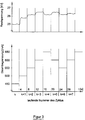
- the associated residual voltage is measured and the current limitation for the following cycle is set on the basis of the measured value obtained, as will be explained below with reference to FIG. 3.
- Time 0 in FIG. 3 can be any time during operation, e.g. B. the switch-on time or the beginning of a normal phase.
- the current limit for cycle k is set to 450 mA.
- the associated residual voltage is approximately 25 kV according to the upper diagram in FIG. 3.
- the current limit is then increased to 500 mA in order to test whether a higher residual voltage is now established.
- the increased current limitation results in a residual voltage of 25.8 kV in cycle k + 1. Since the increase in the current limit has led to an increase in the residual voltage, the current limit is increased again in the following cycle k + 2, this time to 550 mA. There is again an increased residual voltage, namely 26.2 kV.
- an average of the voltage is calculated and stored by evaluating a large number of instantaneous values. As an average z. B. selected the effective voltage.
- test phase follows the normal phase. In the test phase, it should be tested whether the change can be improved with a changed pulse number.
- a pulse number is used which differs from the pulse number of the immediately preceding normal phase by ⁇ 1. Numerous cycles are also run through in the test phase, analogous to the normal phase. After a quasi-steady state has occurred, an average value of the voltage is also calculated and stored in the test phase. This mean is compared with the mean of the associated normal phase.
- the pulse number 5 is used again in the normal phase of the following period m + 1. Since an increase in the number of pulses was unsuccessful in the operating period m, the number of pulses is reduced to 4 in the test phase of the operating period m + 1. The effect again this time is that the mean value of the voltage drops. Therefore, the pulse number is reset to 5 in the normal phase of the operating period m + 2.
- the number of pulses 6 is tried again, again with the result that the mean value of the voltage drops. Consequently, the pulse number 5 is again set in the normal phase in the operating period m + 3.
- the number of pulses 4 is tried again, this time with success, apparently because a parameter of the gas stream to be cleaned has changed in the meantime. It turns out an increased Average voltage. Since the reduction in the number of pulses in the operating period m + 3 was successful, the number of pulses 4 is maintained in the normal phase in the operating period m + 4. In the subsequent test phase, the number of pulses is reduced again, to 3. The effect is negative. Therefore, the number of pulses is reset to 4 in the normal phase of the operating period m + 5.
- the test phase is relatively short compared to the normal phase and the pulse numbers of the normal phase and the subsequent test phase differ only by ⁇ 1, the fluctuations caused by this are relatively small and have little influence on the quality of the separation in individual cases. If, however, the parameters of the gas stream to be cleaned change sustainably over a longer period of time, the method of operation illustrated in FIG. 2 causes the electrostatic filter to always work in the vicinity of the respective optimum operating point.
Landscapes
- Engineering & Computer Science (AREA)
- Automation & Control Theory (AREA)
- Electrostatic Separation (AREA)
- Measurement Of Resistance Or Impedance (AREA)
- Filtering Of Dispersed Particles In Gases (AREA)
- Testing Electric Properties And Detecting Electric Faults (AREA)
- Testing Relating To Insulation (AREA)
- Electrical Discharge Machining, Electrochemical Machining, And Combined Machining (AREA)
- Crystals, And After-Treatments Of Crystals (AREA)
- Networks Using Active Elements (AREA)
Priority Applications (1)
| Application Number | Priority Date | Filing Date | Title |
|---|---|---|---|
| SI9630411T SI0734773T1 (en) | 1995-03-30 | 1996-03-06 | Method for continuous optimization of the operating condition of an electrofilter |
Applications Claiming Priority (2)
| Application Number | Priority Date | Filing Date | Title |
|---|---|---|---|
| DE19511604 | 1995-03-30 | ||
| DE19511604A DE19511604C2 (de) | 1995-03-30 | 1995-03-30 | Verfahren zum fortgesetzten Optimieren des Betriebszustandes eines Elektrofilters |
Publications (3)
| Publication Number | Publication Date |
|---|---|
| EP0734773A2 true EP0734773A2 (fr) | 1996-10-02 |
| EP0734773A3 EP0734773A3 (fr) | 2000-02-02 |
| EP0734773B1 EP0734773B1 (fr) | 2001-10-24 |
Family
ID=7758106
Family Applications (1)
| Application Number | Title | Priority Date | Filing Date |
|---|---|---|---|
| EP96103433A Expired - Lifetime EP0734773B1 (fr) | 1995-03-30 | 1996-03-06 | Méthode pour l'optimisation continu du régime de travail d'un électrofiltre |
Country Status (4)
| Country | Link |
|---|---|
| EP (1) | EP0734773B1 (fr) |
| AT (1) | ATE207388T1 (fr) |
| DE (2) | DE19511604C2 (fr) |
| SI (1) | SI0734773T1 (fr) |
Families Citing this family (1)
| Publication number | Priority date | Publication date | Assignee | Title |
|---|---|---|---|---|
| CN108380391B (zh) * | 2018-02-11 | 2024-01-30 | 洁通科技(北京)有限公司 | 无臭氧双路四电压高压静电除尘器及其控制方法 |
Family Cites Families (8)
| Publication number | Priority date | Publication date | Assignee | Title |
|---|---|---|---|---|
| DE2949786A1 (de) * | 1979-12-11 | 1981-06-19 | Siemens AG, 1000 Berlin und 8000 München | Verfahren zum ermitteln der filterstromgrenze eines elektrofilters |
| DE3275706D1 (en) * | 1981-07-24 | 1987-04-23 | Rodney John Truce | Detecting, measuring and applying back corona parameters on an electrostatic precipitator |
| SE451675B (sv) * | 1983-10-05 | 1987-10-26 | Flaekt Ab | Sett och anordning for att variera en mellan elektrostatiska stoftavskiljares elektroder upptredande spenning |
| JPS6125650A (ja) * | 1984-07-17 | 1986-02-04 | Sumitomo Heavy Ind Ltd | 電気集塵装置の荷電制御方法 |
| GB8431294D0 (en) * | 1984-12-12 | 1985-01-23 | Smidth & Co As F L | Controlling intermittant voltage supply |
| DE3526009A1 (de) * | 1985-07-20 | 1987-01-22 | Metallgesellschaft Ag | Regelverfahren fuer ein elektrofilter |
| SE463353B (sv) * | 1989-03-28 | 1990-11-12 | Flaekt Ab | Saett att reglera stroempulsmatning till en elektrostatisk stoftavskiljare |
| US5311420A (en) * | 1992-07-17 | 1994-05-10 | Environmental Elements Corp. | Automatic back corona detection and protection system |
-
1995
- 1995-03-30 DE DE19511604A patent/DE19511604C2/de not_active Expired - Fee Related
-
1996
- 1996-03-06 DE DE59607969T patent/DE59607969D1/de not_active Expired - Fee Related
- 1996-03-06 EP EP96103433A patent/EP0734773B1/fr not_active Expired - Lifetime
- 1996-03-06 SI SI9630411T patent/SI0734773T1/xx unknown
- 1996-03-06 AT AT96103433T patent/ATE207388T1/de not_active IP Right Cessation
Also Published As
| Publication number | Publication date |
|---|---|
| EP0734773A3 (fr) | 2000-02-02 |
| EP0734773B1 (fr) | 2001-10-24 |
| ATE207388T1 (de) | 2001-11-15 |
| SI0734773T1 (en) | 2002-06-30 |
| DE19511604A1 (de) | 1996-10-02 |
| DE19511604C2 (de) | 1999-08-12 |
| DE59607969D1 (de) | 2001-11-29 |
Similar Documents
| Publication | Publication Date | Title |
|---|---|---|
| DE69009054T2 (de) | Strompulsversorgungssteuerverfahren für einen elektrostatischen abscheider. | |
| EP0206160B1 (fr) | Alimentation de courant pour filtre électrostatique | |
| DE3301772C2 (fr) | ||
| DE4490375C2 (de) | Verfahren zum Steuern der Stromversorgung eines elektrostatischen Abscheiders | |
| DE69400861T2 (de) | Elektro-Abscheider | |
| DE2727858A1 (de) | Elektrische entstaubungsvorrichtung | |
| EP0268934A1 (fr) | Procédé et dispositif pour l'alimentation en énergie d'un précipitateur électrostatique | |
| DE3525557C2 (de) | Verfahren zum Überwachen und Regeln eines elektrostatischen Abscheiders | |
| DE3447719A1 (de) | Impuls-hochspannungsquelle sowie hiermit ausgeruesteter elektrischer staubabscheider mit impulsaufladung | |
| DE2730807A1 (de) | Impulsleistungsgeraet zum anlegen einer impulsspannung an eine kapazitive last | |
| DE3403619A1 (de) | Elektrische stromversorgungsquelle fuer die verwendung in einer elektrostatischen ausfaellvorrichtung | |
| DE2824326A1 (de) | Stromversorgung fuer elektrische bearbeitung | |
| DE3526009C2 (fr) | ||
| DE3249184T1 (de) | Verfahren und einrichtung fuer eine elektrostatische staubausfaellung | |
| DE2728563B2 (de) | Röntgendiagnostikgenerator mit einem einen Hochspannungstransformator speisenden Wechselrichter und einer Steuereinrichtung zur Einstellung der Frequenz des Wechselrichters in Abhängigkeit von der gewählten Röntgenröhrenspannung | |
| DE2113827A1 (de) | Verfahren und Vorrichtung zur elektroerosiven Bearbeitung | |
| EP0209714B1 (fr) | Procédé pour mettre en oeuvre un filtre électrostatique | |
| DE3048979C2 (de) | Verfahren zum Betrieb eines Elektroabscheiders für die Gasentstaubung und Vorrichtung dazu | |
| EP0734773B1 (fr) | Méthode pour l'optimisation continu du régime de travail d'un électrofiltre | |
| DE3114009C2 (fr) | ||
| DE4140228C2 (de) | Verfahren zur Entstaubung von Rauchgasen | |
| DE1814071A1 (de) | Verfahren und Einrichtung zum elektrischen Lichtbogenschweissen mittels Wechselstrom | |
| EP0038505A1 (fr) | Procédé pour porter automatiquement la tension d'un électrofiltre à la limite de décharge | |
| DE3343930A1 (de) | Schaltungsanordnung zum betrieb von leuchtstoff- oder ultraviolett-niederspannungs-entladungslampen | |
| DE10245368A1 (de) | Schweißstromquelle zum Gleich- und Wechselstromschweißen |
Legal Events
| Date | Code | Title | Description |
|---|---|---|---|
| PUAI | Public reference made under article 153(3) epc to a published international application that has entered the european phase |
Free format text: ORIGINAL CODE: 0009012 |
|
| AK | Designated contracting states |
Kind code of ref document: A2 Designated state(s): AT DE DK ES FR GB GR IT NL PT SE |
|
| AX | Request for extension of the european patent |
Free format text: SI PAYMENT 960409 |
|
| RAX | Requested extension states of the european patent have changed |
Free format text: SI PAYMENT 960409 |
|
| PUAL | Search report despatched |
Free format text: ORIGINAL CODE: 0009013 |
|
| AK | Designated contracting states |
Kind code of ref document: A3 Designated state(s): AT DE DK ES FR GB GR IT NL PT SE |
|
| AX | Request for extension of the european patent |
Free format text: SI PAYMENT 19960409 |
|
| 17P | Request for examination filed |
Effective date: 20000411 |
|
| GRAG | Despatch of communication of intention to grant |
Free format text: ORIGINAL CODE: EPIDOS AGRA |
|
| GRAG | Despatch of communication of intention to grant |
Free format text: ORIGINAL CODE: EPIDOS AGRA |
|
| GRAH | Despatch of communication of intention to grant a patent |
Free format text: ORIGINAL CODE: EPIDOS IGRA |
|
| 17Q | First examination report despatched |
Effective date: 20010404 |
|
| GRAH | Despatch of communication of intention to grant a patent |
Free format text: ORIGINAL CODE: EPIDOS IGRA |
|
| GRAA | (expected) grant |
Free format text: ORIGINAL CODE: 0009210 |
|
| AK | Designated contracting states |
Kind code of ref document: B1 Designated state(s): AT DE DK ES FR GB GR IT NL PT SE |
|
| AX | Request for extension of the european patent |
Free format text: SI PAYMENT 19960409 |
|
| PG25 | Lapsed in a contracting state [announced via postgrant information from national office to epo] |
Ref country code: NL Free format text: LAPSE BECAUSE OF FAILURE TO SUBMIT A TRANSLATION OF THE DESCRIPTION OR TO PAY THE FEE WITHIN THE PRESCRIBED TIME-LIMIT Effective date: 20011024 Ref country code: IT Free format text: LAPSE BECAUSE OF FAILURE TO SUBMIT A TRANSLATION OF THE DESCRIPTION OR TO PAY THE FEE WITHIN THE PRESCRIBED TIME-LIMIT;WARNING: LAPSES OF ITALIAN PATENTS WITH EFFECTIVE DATE BEFORE 2007 MAY HAVE OCCURRED AT ANY TIME BEFORE 2007. THE CORRECT EFFECTIVE DATE MAY BE DIFFERENT FROM THE ONE RECORDED. Effective date: 20011024 |
|
| REF | Corresponds to: |
Ref document number: 207388 Country of ref document: AT Date of ref document: 20011115 Kind code of ref document: T |
|
| REF | Corresponds to: |
Ref document number: 59607969 Country of ref document: DE Date of ref document: 20011129 |
|
| REG | Reference to a national code |
Ref country code: GB Ref legal event code: IF02 |
|
| ET | Fr: translation filed | ||
| PG25 | Lapsed in a contracting state [announced via postgrant information from national office to epo] |
Ref country code: PT Free format text: LAPSE BECAUSE OF FAILURE TO SUBMIT A TRANSLATION OF THE DESCRIPTION OR TO PAY THE FEE WITHIN THE PRESCRIBED TIME-LIMIT Effective date: 20020124 Ref country code: DK Free format text: LAPSE BECAUSE OF FAILURE TO SUBMIT A TRANSLATION OF THE DESCRIPTION OR TO PAY THE FEE WITHIN THE PRESCRIBED TIME-LIMIT Effective date: 20020124 |
|
| PG25 | Lapsed in a contracting state [announced via postgrant information from national office to epo] |
Ref country code: GR Free format text: LAPSE BECAUSE OF FAILURE TO SUBMIT A TRANSLATION OF THE DESCRIPTION OR TO PAY THE FEE WITHIN THE PRESCRIBED TIME-LIMIT Effective date: 20020125 |
|
| GBT | Gb: translation of ep patent filed (gb section 77(6)(a)/1977) |
Effective date: 20020105 |
|
| PG25 | Lapsed in a contracting state [announced via postgrant information from national office to epo] |
Ref country code: GB Free format text: LAPSE BECAUSE OF NON-PAYMENT OF DUE FEES Effective date: 20020306 Ref country code: AT Free format text: LAPSE BECAUSE OF NON-PAYMENT OF DUE FEES Effective date: 20020306 |
|
| PG25 | Lapsed in a contracting state [announced via postgrant information from national office to epo] |
Ref country code: SE Free format text: LAPSE BECAUSE OF NON-PAYMENT OF DUE FEES Effective date: 20020307 |
|
| NLV1 | Nl: lapsed or annulled due to failure to fulfill the requirements of art. 29p and 29m of the patents act | ||
| PG25 | Lapsed in a contracting state [announced via postgrant information from national office to epo] |
Ref country code: ES Free format text: LAPSE BECAUSE OF FAILURE TO SUBMIT A TRANSLATION OF THE DESCRIPTION OR TO PAY THE FEE WITHIN THE PRESCRIBED TIME-LIMIT Effective date: 20020430 |
|
| PLBE | No opposition filed within time limit |
Free format text: ORIGINAL CODE: 0009261 |
|
| STAA | Information on the status of an ep patent application or granted ep patent |
Free format text: STATUS: NO OPPOSITION FILED WITHIN TIME LIMIT |
|
| PG25 | Lapsed in a contracting state [announced via postgrant information from national office to epo] |
Ref country code: DE Free format text: LAPSE BECAUSE OF NON-PAYMENT OF DUE FEES Effective date: 20021001 |
|
| 26N | No opposition filed | ||
| EUG | Se: european patent has lapsed |
Ref document number: 96103433.7 |
|
| GBPC | Gb: european patent ceased through non-payment of renewal fee |
Effective date: 20020306 |
|
| PG25 | Lapsed in a contracting state [announced via postgrant information from national office to epo] |
Ref country code: FR Free format text: LAPSE BECAUSE OF NON-PAYMENT OF DUE FEES Effective date: 20021129 |
|
| REG | Reference to a national code |
Ref country code: FR Ref legal event code: ST |