EP0734782A2 - Procédé et appareil pour l'obtention d'un jet de flamme supersonique à onde de choc stabilisée - Google Patents
Procédé et appareil pour l'obtention d'un jet de flamme supersonique à onde de choc stabilisée Download PDFInfo
- Publication number
- EP0734782A2 EP0734782A2 EP96104822A EP96104822A EP0734782A2 EP 0734782 A2 EP0734782 A2 EP 0734782A2 EP 96104822 A EP96104822 A EP 96104822A EP 96104822 A EP96104822 A EP 96104822A EP 0734782 A2 EP0734782 A2 EP 0734782A2
- Authority
- EP
- European Patent Office
- Prior art keywords
- duct
- flow
- passage
- supersonic
- shock
- Prior art date
- Legal status (The legal status is an assumption and is not a legal conclusion. Google has not performed a legal analysis and makes no representation as to the accuracy of the status listed.)
- Granted
Links
- 238000000034 method Methods 0.000 title claims 6
- 230000035939 shock Effects 0.000 claims abstract description 21
- 239000000446 fuel Substances 0.000 claims abstract description 14
- 239000007800 oxidant agent Substances 0.000 claims abstract description 14
- 238000006243 chemical reaction Methods 0.000 claims abstract description 4
- 230000001590 oxidative effect Effects 0.000 claims abstract 10
- 238000002485 combustion reaction Methods 0.000 claims description 11
- 230000008859 change Effects 0.000 claims description 4
- 239000000203 mixture Substances 0.000 claims description 4
- 238000004519 manufacturing process Methods 0.000 claims description 3
- 230000001133 acceleration Effects 0.000 claims 1
- 239000007789 gas Substances 0.000 description 18
- QVGXLLKOCUKJST-UHFFFAOYSA-N atomic oxygen Chemical compound [O] QVGXLLKOCUKJST-UHFFFAOYSA-N 0.000 description 11
- 239000001301 oxygen Substances 0.000 description 11
- 229910052760 oxygen Inorganic materials 0.000 description 11
- 239000002245 particle Substances 0.000 description 6
- 239000000463 material Substances 0.000 description 5
- 238000002844 melting Methods 0.000 description 3
- 230000008018 melting Effects 0.000 description 3
- 238000000576 coating method Methods 0.000 description 2
- 239000000498 cooling water Substances 0.000 description 2
- 239000010432 diamond Substances 0.000 description 2
- 239000000843 powder Substances 0.000 description 2
- 238000005507 spraying Methods 0.000 description 2
- 238000007751 thermal spraying Methods 0.000 description 2
- MYMOFIZGZYHOMD-UHFFFAOYSA-N Dioxygen Chemical compound O=O MYMOFIZGZYHOMD-UHFFFAOYSA-N 0.000 description 1
- 239000000919 ceramic Substances 0.000 description 1
- 239000011248 coating agent Substances 0.000 description 1
- 239000002826 coolant Substances 0.000 description 1
- 238000005520 cutting process Methods 0.000 description 1
- 238000005553 drilling Methods 0.000 description 1
- 230000002349 favourable effect Effects 0.000 description 1
- 239000010438 granite Substances 0.000 description 1
- 238000010438 heat treatment Methods 0.000 description 1
- 230000006872 improvement Effects 0.000 description 1
- 230000000977 initiatory effect Effects 0.000 description 1
- 238000005457 optimization Methods 0.000 description 1
- TWNQGVIAIRXVLR-UHFFFAOYSA-N oxo(oxoalumanyloxy)alumane Chemical compound O=[Al]O[Al]=O TWNQGVIAIRXVLR-UHFFFAOYSA-N 0.000 description 1
- 239000000376 reactant Substances 0.000 description 1
- 239000007787 solid Substances 0.000 description 1
- 239000007921 spray Substances 0.000 description 1
- 238000011105 stabilization Methods 0.000 description 1
- 239000000758 substrate Substances 0.000 description 1
- 230000007704 transition Effects 0.000 description 1
- 238000011144 upstream manufacturing Methods 0.000 description 1
Images

Classifications
-
- B—PERFORMING OPERATIONS; TRANSPORTING
- B05—SPRAYING OR ATOMISING IN GENERAL; APPLYING FLUENT MATERIALS TO SURFACES, IN GENERAL
- B05B—SPRAYING APPARATUS; ATOMISING APPARATUS; NOZZLES
- B05B7/00—Spraying apparatus for discharge of liquids or other fluent materials from two or more sources, e.g. of liquid and air, of powder and gas
- B05B7/16—Spraying apparatus for discharge of liquids or other fluent materials from two or more sources, e.g. of liquid and air, of powder and gas incorporating means for heating or cooling the material to be sprayed
- B05B7/20—Spraying apparatus for discharge of liquids or other fluent materials from two or more sources, e.g. of liquid and air, of powder and gas incorporating means for heating or cooling the material to be sprayed by flame or combustion
- B05B7/201—Spraying apparatus for discharge of liquids or other fluent materials from two or more sources, e.g. of liquid and air, of powder and gas incorporating means for heating or cooling the material to be sprayed by flame or combustion downstream of the nozzle
- B05B7/205—Spraying apparatus for discharge of liquids or other fluent materials from two or more sources, e.g. of liquid and air, of powder and gas incorporating means for heating or cooling the material to be sprayed by flame or combustion downstream of the nozzle the material to be sprayed being originally a particulate material
-
- C—CHEMISTRY; METALLURGY
- C23—COATING METALLIC MATERIAL; COATING MATERIAL WITH METALLIC MATERIAL; CHEMICAL SURFACE TREATMENT; DIFFUSION TREATMENT OF METALLIC MATERIAL; COATING BY VACUUM EVAPORATION, BY SPUTTERING, BY ION IMPLANTATION OR BY CHEMICAL VAPOUR DEPOSITION, IN GENERAL; INHIBITING CORROSION OF METALLIC MATERIAL OR INCRUSTATION IN GENERAL
- C23C—COATING METALLIC MATERIAL; COATING MATERIAL WITH METALLIC MATERIAL; SURFACE TREATMENT OF METALLIC MATERIAL BY DIFFUSION INTO THE SURFACE, BY CHEMICAL CONVERSION OR SUBSTITUTION; COATING BY VACUUM EVAPORATION, BY SPUTTERING, BY ION IMPLANTATION OR BY CHEMICAL VAPOUR DEPOSITION, IN GENERAL
- C23C4/00—Coating by spraying the coating material in the molten state, e.g. by flame, plasma or electric discharge
- C23C4/12—Coating by spraying the coating material in the molten state, e.g. by flame, plasma or electric discharge characterised by the method of spraying
- C23C4/129—Flame spraying
-
- F—MECHANICAL ENGINEERING; LIGHTING; HEATING; WEAPONS; BLASTING
- F23—COMBUSTION APPARATUS; COMBUSTION PROCESSES
- F23C—METHODS OR APPARATUS FOR COMBUSTION USING FLUID FUEL OR SOLID FUEL SUSPENDED IN A CARRIER GAS OR AIR
- F23C3/00—Combustion apparatus characterised by the shape of the combustion chamber
Definitions
- the present invention is directed to a shock-stabilized duct-mode device for creating a high temperature and high velocity flame jet suitable for spraying high melting point materials.
- Flame jets are utilized for general heating purposes as well as specific uses including cutting and drilling of granite and the thermal spraying of metallic or other materials to form coatings on a base material. Where high heat transfer rates and/or supersonic velocity flame jets are required, certain types of flame-producing device have been available. These devices reduce to two basic modes of operation -- the chamber-stabilized mode and the duct-stabilized mode.
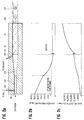
- Figure 1a of the present application is a simplified sketch of a "duct stabilized" device of the type described by Smith et al.
- the burner 10 consists of two bores of different diameter. Oxygen enters the burner 10 through a relatively small diameter bore 12. Fuel, entering bore 12 through passage 13, mixes with the oxygen flow and the combined flow is discharged from bore 12 into the larger duct 11. The oxy-fuel mixture is ignited upon its entry to duct 11 with nearly complete combustion occurring prior to exit of the flame products from duct 11. Supersonic flame 14 extends as a flame-jet beyond duct 11 and is characterized by shock diamonds 16. Metallic powder is injected through duct 16.
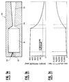
- Figure 3a of the present application is a simplified sketch of a "chamber-stabilized mode" of the type described by Smith et al.
- the "chamber stebilized mode” of Figure 3a utilizes a relatively large volume chamber 31 to stabilize and contain the combustion reactions. Oxygen and fuel are fed under pressure into chamber 31 in burner 30 through ports 32 and 33. A very small nozzle throat 34 with an expanding conical bore 35 expands the hot gas exiting from chamber 31 to extremely high velocity. For an inlet oxygen pressure of 500 psig (Figs. 1b and 1c) the exit gas velocity is over 8,000 ft/sec. Where high particle impact velocities are required for thermal spray process optimization, the "chamber mode" is superior to the "duct mode". However, as the oxygen pressure is raised to produce favorable particle velocities, unacceptable heat losses to the cooling water (not shown) occur. Higher melting point materials such as aluminum oxide remain solid and will not form a coating.
- the "duct mode”, with a much smaller “wetted surface” available for heat transfer from the flame to the cooling water (not shown) has much higher flame-jet temperatures than for the "chamber mode". Thus, even though particle velocities are much lower, it may have to be selected for certain types of thermal spraying.
- the present invention is an improvement in the duct-stabilized mode by providing a change in the means for continuously initiating combustion in an oxygen-fuel mixture and keeping stable flame reactions within a high-velocity flow stream of these reactants.
- the present invention provides a new and improved flame jet apparatus comprised of a body having an entry passage of relatively small cross-sectional area and an expanding supersonic nozzle section 23 connected to a cylindrical duct of extended length.
- the present invention also provides a new and improved method for producing a supersonic jet stream of high temperature using the foregoing apparatus comprising introducing a mixed flow of oxidizer gas and fuel to flow at supersonic speed through an initial portion of an extended duct and causing a shock to form within the duct forcing a sufficient change in pressure, temperature, velocity and turbulence to initiate and/or maintain combustion reactions downstream of said shock thereby extending the combustion through the remaining duct length and beyond the duct exit in the form of a supersonic jet stream.
- Figure 1a is a schematic cross-sectional view of a conventional device for operating in the "duct mode”.
- Figure 1b is a plot of the pressure drop of the gas in its passage through the device of Figure 1a.
- Figure 1c is a plot of the gas velocity in the flow passing through the device of Figure 1a.
- Figure 2a is a schematic cross-sectional view of the device of this invention for operating in the shock-stabilized duct mode.
- Figure 2b is a plot of the pressure drop of the gas in its passage through the device of Figure 2a.
- Figure 2c is a plot of the gas velocity in the flow passing through the device of Figure 2a.
- Figure 3 is a schematic cross-sectional view of a conventional device for operating in the chamber stabilized mode.
- burner 20 consists of a body piece containing an entry passage 22 of relatively small cross-sectional area and an expanding supersonic nozzle section 23 connected to a cylindrical duct 21 of extended length which has larger cross-sectional area than the passage 22.
- Oxygen and fuel introduced to passage 22 through ports 24 and 25 mix together and reach sonic velocity prior to entering nozzle expansion 23.
- the powder to be coated on a substrate is injected through port 29.
- the discontinuity formed at the wall where the expanding section 23 meets the cylindrical duct 21 forms a weak shock 40.
- the shock-stabilized duct mode can create jet velocities about double conventional duct mode devices. Jet temperatures remain high allowing ceramic spraying. This device compliments a chamber mode device where high melting point materials must be sprayed. The geometry is much simpler and length of operation is greatly extended as the small nozzle throat 34 of the chamber mode ( Figure 3a) is eliminated. At high pressure, using pure oxygen as the oxidizer, throat life is limited by intense heat transfer requirements at the throat.
- both the pressure and velocity plots ( Figures 1b and 1c) of the duct mode device are distinctly different from those of the shock-stabilized duct mode of the present invention. Smooth transitions exist for the duct mode.
- the shock in the device according to the present invention causes nearly instantaneous changes in both pressure and velocity.
Landscapes
- Engineering & Computer Science (AREA)
- Chemical & Material Sciences (AREA)
- Combustion & Propulsion (AREA)
- Mechanical Engineering (AREA)
- Plasma & Fusion (AREA)
- Physics & Mathematics (AREA)
- General Engineering & Computer Science (AREA)
- Chemical Kinetics & Catalysis (AREA)
- Materials Engineering (AREA)
- Metallurgy (AREA)
- Organic Chemistry (AREA)
- Gas Burners (AREA)
- Coating By Spraying Or Casting (AREA)
- Nozzles (AREA)
Applications Claiming Priority (2)
| Application Number | Priority Date | Filing Date | Title |
|---|---|---|---|
| US414780 | 1995-03-30 | ||
| US08/414,780 US5531590A (en) | 1995-03-30 | 1995-03-30 | Shock-stabilized supersonic flame-jet method and apparatus |
Publications (3)
| Publication Number | Publication Date |
|---|---|
| EP0734782A2 true EP0734782A2 (fr) | 1996-10-02 |
| EP0734782A3 EP0734782A3 (fr) | 1997-04-23 |
| EP0734782B1 EP0734782B1 (fr) | 2003-07-09 |
Family
ID=23642933
Family Applications (1)
| Application Number | Title | Priority Date | Filing Date |
|---|---|---|---|
| EP96104822A Expired - Lifetime EP0734782B1 (fr) | 1995-03-30 | 1996-03-26 | Procédé et appareil pour l'obtention d'un jet de flamme supersonique à onde de choc stabilisée |
Country Status (4)
| Country | Link |
|---|---|
| US (1) | US5531590A (fr) |
| EP (1) | EP0734782B1 (fr) |
| JP (1) | JPH09176823A (fr) |
| DE (1) | DE69628966T2 (fr) |
Families Citing this family (10)
| Publication number | Priority date | Publication date | Assignee | Title |
|---|---|---|---|---|
| US5634415A (en) * | 1996-04-23 | 1997-06-03 | China Textile Institute | Adjustable rack apparatus |
| RU2100474C1 (ru) * | 1996-11-18 | 1997-12-27 | Общество с ограниченной ответственностью "Обнинский центр порошкового напыления" | Устройство для газодинамического нанесения покрытий из порошковых материалов |
| US6635362B2 (en) | 2001-02-16 | 2003-10-21 | Xiaoci Maggie Zheng | High temperature coatings for gas turbines |
| DE10126100A1 (de) * | 2001-05-29 | 2002-12-05 | Linde Ag | Verfahren und Vorrichtung zum Kaltgasspritzen |
| US7108893B2 (en) * | 2002-09-23 | 2006-09-19 | Delphi Technologies, Inc. | Spray system with combined kinetic spray and thermal spray ability |
| US6948306B1 (en) * | 2002-12-24 | 2005-09-27 | The United States Of America As Represented By The Secretary Of The Navy | Apparatus and method of using supersonic combustion heater for hypersonic materials and propulsion testing |
| US8162239B2 (en) * | 2007-05-21 | 2012-04-24 | Thomas Francis Hursen | Air gun safety nozzle |
| US8171659B2 (en) * | 2007-12-10 | 2012-05-08 | Thomas Francis Hursen | Method and apparatus for selective soil fracturing, soil excavation or soil treatment using supersonic pneumatic nozzle with integral fluidized material injector |
| US7628606B1 (en) * | 2008-05-19 | 2009-12-08 | Browning James A | Method and apparatus for combusting fuel employing vortex stabilization |
| US8992656B2 (en) | 2011-12-21 | 2015-03-31 | Praxair Technology, Inc. | Controllable solids injection |
Family Cites Families (13)
| Publication number | Priority date | Publication date | Assignee | Title |
|---|---|---|---|---|
| US2510482A (en) * | 1945-05-30 | 1950-06-06 | Eclipse Fuel Eng Co | Pilot burner using gaseous fuel and air under pressure |
| LU34279A1 (fr) * | 1955-03-28 | |||
| LU34348A1 (fr) * | 1955-05-02 | |||
| US3190560A (en) * | 1963-06-07 | 1965-06-22 | Eutectic Welding Alloys | Flame-spraying torch |
| US4004735A (en) * | 1974-06-12 | 1977-12-25 | Zverev Anatoly | Apparatus for detonating application of coatings |
| US4165364A (en) * | 1976-08-04 | 1979-08-21 | Sid Richardson Carbon & Gasoline Co. | Carbon black reactor with axial flow burner |
| US4172558A (en) * | 1977-04-19 | 1979-10-30 | Bondarenko Alexandr S | Apparatus for explosive application of coatings |
| EP0163776A3 (fr) * | 1984-01-18 | 1986-12-30 | James A. Browning | Procédé de pulvérisation à flamme supersonique de grande concentration et appareil à alimentation améliorée |
| US4836447A (en) * | 1988-01-15 | 1989-06-06 | Browning James A | Duct-stabilized flame-spray method and apparatus |
| US5019686A (en) * | 1988-09-20 | 1991-05-28 | Alloy Metals, Inc. | High-velocity flame spray apparatus and method of forming materials |
| DE8909503U1 (de) * | 1989-08-08 | 1989-09-28 | UTP Schweißmaterial GmbH & Co KG, 7812 Bad Krozingen | Hochgeschwindigkeitsflammspritzpistole |
| US5234164A (en) * | 1990-05-22 | 1993-08-10 | Utp Schweibmaterial Gmbh & Co. Kg | Device for high speed flame spraying of refractory wire of powder weld filler for the coating of surfaces |
| US5340615A (en) * | 1993-06-01 | 1994-08-23 | Browning James A | Method to produce non-stressed flame spray coating and bodies |
-
1995
- 1995-03-30 US US08/414,780 patent/US5531590A/en not_active Expired - Fee Related
-
1996
- 1996-03-26 EP EP96104822A patent/EP0734782B1/fr not_active Expired - Lifetime
- 1996-03-26 DE DE69628966T patent/DE69628966T2/de not_active Expired - Fee Related
- 1996-03-29 JP JP8077618A patent/JPH09176823A/ja active Pending
Also Published As
| Publication number | Publication date |
|---|---|
| US5531590A (en) | 1996-07-02 |
| EP0734782B1 (fr) | 2003-07-09 |
| JPH09176823A (ja) | 1997-07-08 |
| DE69628966D1 (de) | 2003-08-14 |
| DE69628966T2 (de) | 2004-04-22 |
| EP0734782A3 (fr) | 1997-04-23 |
Similar Documents
| Publication | Publication Date | Title |
|---|---|---|
| US5271965A (en) | Thermal spray method utilizing in-transit powder particle temperatures below their melting point | |
| US5120582A (en) | Maximum combustion energy conversion air fuel internal burner | |
| US4634611A (en) | Flame spray method and apparatus | |
| US5330798A (en) | Thermal spray method and apparatus for optimizing flame jet temperature | |
| US6245390B1 (en) | High-velocity thermal spray apparatus and method of forming materials | |
| US4343605A (en) | Method of dual fuel operation of an internal burner type ultra-high velocity flame jet apparatus | |
| US8827176B2 (en) | HVOF torch with fuel surrounding oxidizer | |
| US5019686A (en) | High-velocity flame spray apparatus and method of forming materials | |
| US5206059A (en) | Method of forming metal-matrix composites and composite materials | |
| EP0473906B1 (fr) | Ensemble de brûleur d'oxygène-combustible et le régime | |
| JP2651969B2 (ja) | 流体バーナー | |
| JP2000507648A (ja) | 溶射システム | |
| JP2007232364A (ja) | 燃料およびオキシダント流の分離噴射を含む燃焼方法およびその燃焼 | |
| US20110229649A1 (en) | Supersonic material flame spray method and apparatus | |
| US4836447A (en) | Duct-stabilized flame-spray method and apparatus | |
| JPH10505706A (ja) | 高速、高圧プラズマ銃 | |
| US5531590A (en) | Shock-stabilized supersonic flame-jet method and apparatus | |
| WO2009155702A1 (fr) | Système et procédé de projection d'oxygaz basse température et procédé permettant de déposer des couches à l'aide de ceux-ci | |
| CN112742620B (zh) | 高速含氧空气燃料热喷涂装置 | |
| US5372857A (en) | Method of high intensity steam cooling of air-cooled flame spray apparatus | |
| US5384164A (en) | Flame sprayed coatings of material from solid wire or rods | |
| EP0163776A2 (fr) | Procédé de pulvérisation à flamme supersonique de grande concentration et appareil à alimentation améliorée | |
| EP1497472B1 (fr) | Injection de solides dans des liquides par jet de gaz supersonique enveloppant | |
| JPH06312149A (ja) | 溶射による高密度酸素コーティング | |
| RU2163864C2 (ru) | Газодинамический металлизатор-термоотбойник |
Legal Events
| Date | Code | Title | Description |
|---|---|---|---|
| PUAI | Public reference made under article 153(3) epc to a published international application that has entered the european phase |
Free format text: ORIGINAL CODE: 0009012 |
|
| AK | Designated contracting states |
Kind code of ref document: A2 Designated state(s): CH DE LI LU |
|
| PUAL | Search report despatched |
Free format text: ORIGINAL CODE: 0009013 |
|
| AK | Designated contracting states |
Kind code of ref document: A3 Designated state(s): CH DE LI LU |
|
| 17P | Request for examination filed |
Effective date: 19970506 |
|
| 17Q | First examination report despatched |
Effective date: 19990910 |
|
| GRAH | Despatch of communication of intention to grant a patent |
Free format text: ORIGINAL CODE: EPIDOS IGRA |
|
| GRAH | Despatch of communication of intention to grant a patent |
Free format text: ORIGINAL CODE: EPIDOS IGRA |
|
| GRAA | (expected) grant |
Free format text: ORIGINAL CODE: 0009210 |
|
| AK | Designated contracting states |
Designated state(s): CH DE LI LU |
|
| REG | Reference to a national code |
Ref country code: CH Ref legal event code: EP |
|
| REF | Corresponds to: |
Ref document number: 69628966 Country of ref document: DE Date of ref document: 20030814 Kind code of ref document: P |
|
| REG | Reference to a national code |
Ref country code: CH Ref legal event code: NV Representative=s name: ING. MARCO ZARDI C/O M. ZARDI & CO. S.A. |
|
| PGFP | Annual fee paid to national office [announced via postgrant information from national office to epo] |
Ref country code: CH Payment date: 20040322 Year of fee payment: 9 |
|
| PG25 | Lapsed in a contracting state [announced via postgrant information from national office to epo] |
Ref country code: LU Free format text: LAPSE BECAUSE OF NON-PAYMENT OF DUE FEES Effective date: 20040326 |
|
| PGFP | Annual fee paid to national office [announced via postgrant information from national office to epo] |
Ref country code: DE Payment date: 20040430 Year of fee payment: 9 |
|
| PLBE | No opposition filed within time limit |
Free format text: ORIGINAL CODE: 0009261 |
|
| STAA | Information on the status of an ep patent application or granted ep patent |
Free format text: STATUS: NO OPPOSITION FILED WITHIN TIME LIMIT |
|
| 26N | No opposition filed |
Effective date: 20040414 |
|
| PG25 | Lapsed in a contracting state [announced via postgrant information from national office to epo] |
Ref country code: LI Free format text: LAPSE BECAUSE OF NON-PAYMENT OF DUE FEES Effective date: 20050331 Ref country code: CH Free format text: LAPSE BECAUSE OF NON-PAYMENT OF DUE FEES Effective date: 20050331 |
|
| PG25 | Lapsed in a contracting state [announced via postgrant information from national office to epo] |
Ref country code: DE Free format text: LAPSE BECAUSE OF NON-PAYMENT OF DUE FEES Effective date: 20051001 |
|
| REG | Reference to a national code |
Ref country code: CH Ref legal event code: PL |