EP0734831A2 - Verfahren zum Spritzgiessen mehrschichtiger Gegenstände und Form dafür - Google Patents
Verfahren zum Spritzgiessen mehrschichtiger Gegenstände und Form dafür Download PDFInfo
- Publication number
- EP0734831A2 EP0734831A2 EP96302156A EP96302156A EP0734831A2 EP 0734831 A2 EP0734831 A2 EP 0734831A2 EP 96302156 A EP96302156 A EP 96302156A EP 96302156 A EP96302156 A EP 96302156A EP 0734831 A2 EP0734831 A2 EP 0734831A2
- Authority
- EP
- European Patent Office
- Prior art keywords
- die
- vacuum suction
- skin member
- surface skin
- upper die
- Prior art date
- Legal status (The legal status is an assumption and is not a legal conclusion. Google has not performed a legal analysis and makes no representation as to the accuracy of the status listed.)
- Granted
Links
- 238000000034 method Methods 0.000 title claims abstract description 53
- 238000000465 moulding Methods 0.000 title claims abstract description 21
- 230000000712 assembly Effects 0.000 title claims description 8
- 238000000429 assembly Methods 0.000 title claims description 8
- 239000011347 resin Substances 0.000 claims abstract description 66
- 229920005989 resin Polymers 0.000 claims abstract description 66
- 230000002093 peripheral effect Effects 0.000 claims abstract description 37
- 239000000463 material Substances 0.000 claims description 19
- 238000001746 injection moulding Methods 0.000 claims description 6
- 230000000717 retained effect Effects 0.000 abstract description 8
- 239000000047 product Substances 0.000 description 12
- 230000002349 favourable effect Effects 0.000 description 7
- 230000000694 effects Effects 0.000 description 3
- 238000007789 sealing Methods 0.000 description 3
- 230000002411 adverse Effects 0.000 description 2
- 238000004519 manufacturing process Methods 0.000 description 2
- -1 polypropylene Polymers 0.000 description 2
- 239000004698 Polyethylene Substances 0.000 description 1
- 239000004743 Polypropylene Substances 0.000 description 1
- 239000003086 colorant Substances 0.000 description 1
- 238000007796 conventional method Methods 0.000 description 1
- 230000002950 deficient Effects 0.000 description 1
- 239000000945 filler Substances 0.000 description 1
- 239000012467 final product Substances 0.000 description 1
- 239000006260 foam Substances 0.000 description 1
- 229920000573 polyethylene Polymers 0.000 description 1
- 229920001155 polypropylene Polymers 0.000 description 1
- 239000000454 talc Substances 0.000 description 1
- 229910052623 talc Inorganic materials 0.000 description 1
Images



Classifications
-
- B—PERFORMING OPERATIONS; TRANSPORTING
- B29—WORKING OF PLASTICS; WORKING OF SUBSTANCES IN A PLASTIC STATE IN GENERAL
- B29C—SHAPING OR JOINING OF PLASTICS; SHAPING OF MATERIAL IN A PLASTIC STATE, NOT OTHERWISE PROVIDED FOR; AFTER-TREATMENT OF THE SHAPED PRODUCTS, e.g. REPAIRING
- B29C45/00—Injection moulding, i.e. forcing the required volume of moulding material through a nozzle into a closed mould; Apparatus therefor
- B29C45/14—Injection moulding, i.e. forcing the required volume of moulding material through a nozzle into a closed mould; Apparatus therefor incorporating preformed parts or layers, e.g. injection moulding around inserts or for coating articles
-
- B—PERFORMING OPERATIONS; TRANSPORTING
- B29—WORKING OF PLASTICS; WORKING OF SUBSTANCES IN A PLASTIC STATE IN GENERAL
- B29C—SHAPING OR JOINING OF PLASTICS; SHAPING OF MATERIAL IN A PLASTIC STATE, NOT OTHERWISE PROVIDED FOR; AFTER-TREATMENT OF THE SHAPED PRODUCTS, e.g. REPAIRING
- B29C33/00—Moulds or cores; Details thereof or accessories therefor
- B29C33/12—Moulds or cores; Details thereof or accessories therefor with incorporated means for positioning inserts, e.g. labels
- B29C33/14—Moulds or cores; Details thereof or accessories therefor with incorporated means for positioning inserts, e.g. labels against the mould wall
- B29C33/18—Moulds or cores; Details thereof or accessories therefor with incorporated means for positioning inserts, e.g. labels against the mould wall using vacuum
-
- B—PERFORMING OPERATIONS; TRANSPORTING
- B29—WORKING OF PLASTICS; WORKING OF SUBSTANCES IN A PLASTIC STATE IN GENERAL
- B29C—SHAPING OR JOINING OF PLASTICS; SHAPING OF MATERIAL IN A PLASTIC STATE, NOT OTHERWISE PROVIDED FOR; AFTER-TREATMENT OF THE SHAPED PRODUCTS, e.g. REPAIRING
- B29C43/00—Compression moulding, i.e. applying external pressure to flow the moulding material; Apparatus therefor
- B29C43/02—Compression moulding, i.e. applying external pressure to flow the moulding material; Apparatus therefor of articles of definite length, i.e. discrete articles
- B29C43/18—Compression moulding, i.e. applying external pressure to flow the moulding material; Apparatus therefor of articles of definite length, i.e. discrete articles incorporating preformed parts or layers, e.g. compression moulding around inserts or for coating articles
- B29C43/183—Compression moulding, i.e. applying external pressure to flow the moulding material; Apparatus therefor of articles of definite length, i.e. discrete articles incorporating preformed parts or layers, e.g. compression moulding around inserts or for coating articles the preformed layer being a lining, e.g. shaped in the mould before compression moulding, or a preformed shell adapted to the shape of the mould
-
- B—PERFORMING OPERATIONS; TRANSPORTING
- B29—WORKING OF PLASTICS; WORKING OF SUBSTANCES IN A PLASTIC STATE IN GENERAL
- B29C—SHAPING OR JOINING OF PLASTICS; SHAPING OF MATERIAL IN A PLASTIC STATE, NOT OTHERWISE PROVIDED FOR; AFTER-TREATMENT OF THE SHAPED PRODUCTS, e.g. REPAIRING
- B29C70/00—Shaping composites, i.e. plastics material comprising reinforcements, fillers or preformed parts, e.g. inserts
- B29C70/68—Shaping composites, i.e. plastics material comprising reinforcements, fillers or preformed parts, e.g. inserts by incorporating or moulding on preformed parts, e.g. inserts or layers, e.g. foam blocks
- B29C70/78—Moulding material on one side only of the preformed part
-
- B—PERFORMING OPERATIONS; TRANSPORTING
- B29—WORKING OF PLASTICS; WORKING OF SUBSTANCES IN A PLASTIC STATE IN GENERAL
- B29L—INDEXING SCHEME ASSOCIATED WITH SUBCLASS B29C, RELATING TO PARTICULAR ARTICLES
- B29L2031/00—Other particular articles
- B29L2031/30—Vehicles, e.g. ships or aircraft, or body parts thereof
- B29L2031/3005—Body finishings
- B29L2031/3014—Door linings
-
- Y—GENERAL TAGGING OF NEW TECHNOLOGICAL DEVELOPMENTS; GENERAL TAGGING OF CROSS-SECTIONAL TECHNOLOGIES SPANNING OVER SEVERAL SECTIONS OF THE IPC; TECHNICAL SUBJECTS COVERED BY FORMER USPC CROSS-REFERENCE ART COLLECTIONS [XRACs] AND DIGESTS
- Y10—TECHNICAL SUBJECTS COVERED BY FORMER USPC
- Y10S—TECHNICAL SUBJECTS COVERED BY FORMER USPC CROSS-REFERENCE ART COLLECTIONS [XRACs] AND DIGESTS
- Y10S425/00—Plastic article or earthenware shaping or treating: apparatus
- Y10S425/06—Vacuum
Definitions
- the present invention relates to a method and a die assembly for molding laminated assemblies which are suitable for use as automotive upholstery components such as automotive door trims, and in particular to a method and a die assembly for molding two-element laminated assemblies, which consist of a resin core member and a surface skin member covering a part of the surface of the resin core member, so as to achieve a highly attractive external appearance while maintaining a favorable surface texture and cushioning property.
- FIG 11 shows an automotive door trim given as an example of typical conventional automotive upholstery component.
- This automotive door trim 1 conventionally consisted of a two-element molded assembly having an upper potion 1a and a lower portion 1b having different appearances (including their colors) to enhance its attractive appearance. Normally, the upper portion 1a and the lower portions 1b were fabricated separately, and were joined by using screws .
- Such a molded assembly typically comprises a resin core member 2 molded into a curved shape, and provided with a sufficient rigidity to retain its shape and to be mounted on a vehicle body panel, and a surface skin member 3 covering a part of the resin core member 2.
- a resin core member 2 molded into a curved shape, and provided with a sufficient rigidity to retain its shape and to be mounted on a vehicle body panel, and a surface skin member 3 covering a part of the resin core member 2.
- the surface of the resin core member 2 is covered by the surface skin member 3.
- the lower potion 1b no surface skin member is used, and the resin core member 2 is exposed so that a contrasting appearance may be created in relation with the upper portion 1a.
- the upper die 5 is lowered to its bottom dead center to thereby close the upper and lower dies 4 and 5 upon each other so that the resin core member 2 is mold press formed into the prescribed shape while the surface skin member 3 is integrally attached to the corresponding part of the surface of the resin core member 2.
- the molding of the entire automotive door trim 1 can thus completed as a single process.
- the surface skin member 3 is retained to a part of the die surface of the upper die 5 by vacuum suction, but the force of this vacuum suction was conventionally not strong enough to entirely prevent the skin member 3 from shifting under the pressure of the semi-molten resin during the mold press forming process, and, also, some of the semi-molten resin from leaking out to the surface of the surface skin member 3.
- the edge of the surface skin member 3 tends to create an unsightly view, and this is known to severely impair the appearance of the product.
- any positive tension is not applied to the surface skin member during the process of mold press forming, the surface skin member 3 tends to be dragged by the die surface, and creases may be produced in the peripheral part of the product.
- a primary object of the present invention is to provide a method for molding laminated assemblies such as automotive door trims including a surface skin member and a resin core member which allows the surface skin member can be attached to a part of the surface member of the resin core member in an accurate manner and without causing any undesirable appearances of the surface skin member.
- a second object of the present invention is to provide a method for molding laminated assemblies including a surface skin member and a resin core member which allows the surface skin member to be securely and readily retained on an upper die of the die assembly for integrally mold press forming the assembly.
- a third object of the present invention is to provide a die assembly device which is suitable for implementing the method of the present invention.
- a fourth object of the present invention is to provide a die assembly device for molding laminated assemblies including a surface skin member and a resin core which can prevent any creases and any waviness from developing in the surface during the process of integrally mold press forming the assembly.
- a fifth object of the present invention is to provide a die assembly device which can prevent the material for the resin core member from oozing out to the surface of the surface skin member via the peripheral edge thereof.
- a sixth object of the present invention is to provide a die assembly device which allows a laminated assembly to be molded in a favorable fashion even when the part of the resin core member covered by the surface skin member has a highly curved contour.
- a method for molding laminated assemblies essentially consisting of a resin core member and a surface skin member covering at least a part of the resin core member, comprising the steps of: molding a surface skin member to an approximate shape of a final shape thereof; preparing a die assembly for mold press forming including an upper die and a lower die which are adapted to be selectively closed upon each other; mounting the surface skin member on a part of a die surface of the upper die, the surface skin member being closely attached to the die surface of the upper die along a periphery of the surface skin member by vacuum suction means provided in an outer peripheral groove provided along an outer periphery of a cavity of the upper die; supplying semi-molten resin material a cavity defined between the upper and lower dies; and finally closing the upper and lower dies so that the resin core member is mold press formed into a prescribed shape, and that the surface skin member is integrally attached to a part of a surface of the resin core member.
- the surface skin member can be uniformly secured along the peripheral part thereof, and, hence, any waviness or creases are prevented from developing along the peripheral part of the surface skin member. Because the surface skin member is more securely retained to the die surface of the upper die than heretofore possible without creating any permanent marks on the surface skin member, the shifting of the surface skin member due to the pressure of the resin material during the mold press forming process can be avoided, and the resin material is prevented from showing on the surface of the surface skin member. Also, because the surface skin member is so securely attached to the upper die before the mold press forming process that adverse effects which may arise from the heat and pressure of the resin material can be avoided.
- This method can be implemented in a favorable fashion by using a die assembly device, comprising: a die assembly for mold press forming, including an upper die and a lower die adapted to be closed upon each other; means for selectively closing the die assembly; and an injection molding device for supplying at least soften resin material serving as material for the resin core member over a die surface of the lower die; wherein the die assembly comprises a peripheral groove extending at least partly along a peripheral part of a cavity defined in a die surface of the upper die; a plurality of vacuum suction holes arranged in a bottom region of the groove; and vacuum suction means communicating with the vacuum suction holes for producing a negative pressure in the groove.
- the lateral edges defining the groove provides an additional force of engagement for retaining the surface skin member to the upper die, and this effect can be enhanced by defining the groove by a relatively sharp corner along each lateral edge thereof.
- the die assembly further comprises additional vacuum suction holes communicated with vacuum suction means inside the cavity of the upper die for producing a force for retaining a selected part of the surface skin member to the die surface of the upper die.
- a porous member embedded in the upper die may be used instead of the additional vacuum suction holes. Because the peripheral edge provides a favorable sealing effect, these additional vacuum suction holes and the porous member can produce a particularly strong retaining force.
- inner ends of at least part of the vacuum suction holes in the upper die may be countersunk so to adjust an effective length of each of the vacuum suction holes and to thereby control a vacuum suction force produced by each of the vacuum suction holes.
- Figure 1 is a front view showing an automotive door trim fabricated by the method of the present invention
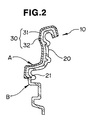
- Figure 2 is a sectional view showing the structure of the automotive door trim
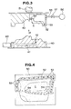
- Figure 3 is a sectional view showing the overall structure of the molding die assembly used for implementing the method of the present invention
- Figure 4 is a view illustrating the vacuum suction holes arranged in the upper die of the die assembly device for mold press forming
- Figures 5 to 7 are sectional views showing different steps of the method of the present invention applied to the fabrication of the automotive door trim.
- the automotive door trim 10 essential consists of a resin core member 20 molded into a desired curved shape, and a surface skin member 30 integrally attached to a part of the resin core member 20.
- the resin core member 20 is made of polypropylene resin mixed with a filler such as talc, and is molded into a complicated curved shape by the mold press forming process as described hereinafter. During this mold press forming process, the surface skin member 30 us integrally attached to a part of the surface of the resin core member 20.
- the surface skin member 30 comprises a top layer 31 made of a PVC sheet, and a foamed lining layer 32 made of polyethylene foam.
- a groove 21 having a depth in the rage of 5 to 10 mm is formed in the resin core member 20 along the lower periphery of the surface skin member 30. By fitting the lower edge of the surface skin member 30 in this groove 11, the appearance of the surface skin member 30 along its periphery is improved.
- the automotive door trim 10 which is made by the method of the present invention consists of an upper portion A in which the surface skin member 30 covers the resin core member 20, and a lower portion B in which the resin core member 20 is exposed so that contrasting appearances may be created between the upper and lower portions A and B. Therefore, as compared to the conventional door trim made by a two-element molded assembly, because the resin core member 20 is unitary or is integrally formed, the manufacturing steps can be simplified. In particular, the need for joining the lower member and the upper member together with screws or the like can be eliminated, and a substantial reduction in cost can be achieved.
- the laminated assembly of the resin core member 20 and the surface skin member 30 provides a uniform cushioning property over the entire surface of the upper portion A, and is free from creases along its periphery. In particular, a favorable appearance is achieved along the boundary between the upper portion A and the lower portion B.
- a primary feature of the present invention is to allow an automotive door trim which has a favorable cushioning property and an attractive appearance to be produced in a highly simple manner.
- the molding die assembly used in the method of the present invention comprises a lower die 40 for mold press forming having a die surface of a desired configuration, an upper die 50 for mold press forming adapted to be moved vertically by a prescribed stroke, and an injection molding device 60 connected to the lower die 40 for supplying semi-molten resin material M serving as the material for the resin core member 20.
- the lower die 40 for mold press forming is incorporated with a manifold 41 which is communicated with the nozzle of the injection molding device 60, and a plurality of gates 42 each communicating with this manifold 41 are provided in prescribed locations of the lower die 40.
- the upper die 50 for mold press forming which is located above the lower die 40, is adapted to move vertically by a prescribed stroke by a lifting cylinder 51, and is provided with a die surface which conforms to the surface contour of the automotive door trim 10 illustrated in Figures 1 and 2.
- the upper die 50 is additionally provided with special vacuum suction means for securely retaining the surface skin member 30 when it is mounted on the upper die 50. More specifically, a peripheral groove 52 is formed along the outer periphery of the cavity C of the upper die 50, and a plurality of relatively large vacuum suction holes 53 are formed in the bottom surface of the peripheral groove 52 at a prescribed pitch along the length of the groove 52.
- the cavity C of the upper die 50 is also provided with a multitude of small vacuum suction holes 54 at locations where vacuum suction force is desired to be adapted to the shape of the product, such as the parts corresponding to recessed parts of the product, without leaving any marks on the product.
- the width and depth of the peripheral groove 52 are 6 mm and 5 mm, respectively, and the diameter of each of the larger vacuum suction holes 53 is 6 mm while that of the smaller vacuum suction holes 54 is 0.3 mm.
- the pitch of the vacuum suction holes 53 provided in the peripheral groove 52 is selected at 30 mm.
- the two sets of vacuum suction holes 53 and 54 are communicated with a vacuum suction conduit 55 which is in turn connected to a vacuum suction pump 56.
- the vacuum suction conduit 55 is provided with an on-off valve 57.
- Figure 5 shows how the surface skin member 30 is mounted on a part of the die surface of the upper die 50.
- the peripheral groove 52 is provided in the die surface of the upper die 50 along the periphery of the cavity C, and the vacuum suction holes 53 having a relatively large diameter are arranged along the length of the peripheral groove 52. Additionally, the vacuum suction holes 53 of a smaller diameter are arranged more densely within the cavity C. As a result, the force for retaining the surface skin member 30 to the die surface of the upper die 50 is significantly increased, and the problems with the prior art are eliminated.
- the surface skin member 30 is already provisionally molded to an approximate shape of the final product by a thermal molding process such as a vacuum molding process.
- a thermal molding process such as a vacuum molding process.
- the three sides of the surface skin member 30 (excluding the side defining a boundary line on the door trim) are securely retained by the vacuum suction force of the larger vacuum suction holes 53 provided in the outer peripheral groove 52, and as illustrated in Figure 5 in an enlarged scale, the surface skin member 30 is doubly sealed at the two corners of the outer peripheral groove 52 so that a highly effective sealing is accomplished along the peripheral part of the surface skin member 30.
- the vacuum suction force produced by the vacuum suction holes 54 provided within the cavity is increased, and the surface skin member 30 can be firmly secured to the desired part of the die surface of the upper die 50. Therefore, as opposed to the prior art, creasing of the surface skin member as illustrated in Figure 12, and leaking of the resin material from a gap created between the surface skin member and the die surface can be avoided.
- the upper die 50 is lowered by a prescribed stroke by the action of the lifting cylinder 51 until a gap of approximately 50 mm is defined between the upper and lower dies 40 and 50, and semi-molten resin material serving as the material for the resin core member 20 is distributed to the prescribed parts of the die surface of the lower die 40 from the injection molding device 60 via the hot runner 41 and the gates 42 as illustrated in Figure 6.
- the surface skin member 50 is closely attached to the die surface of the upper die 50, a sufficient clearance is defined in relation with the semi-molten resin M, and the surface skin member 50 is thereby protected from any adverse influences of the heat of the semi-molten resin M.
- the upper die 50 is lowered to its lower dead point, and the resin core member 20 is molded into the prescribed shape by closing of the upper and lower dies 40 and 50 while the surface skin member 30 is integrally attached to a part of the surface of the resin core member 20.
- the pressure of the semi-resin material M affects the surface skin member 30, but because the surface skin member 30 is firmly attached to the die surface of the upper die 50, the surface skin member 30 is prevented from shifting or creasing.
- the surface skin member 30 can be neatly attached to the resin core member 20, and the resin material would not leak out at the boundary of the surface skin member 30.
- Figures 8 and 9 show another embodiment of the die assembly device which can be used for implementing the method of the present invention.
- this embodiment in addition to that a plurality of large vacuum suction holes 53 are provided at a prescribed pitch in the outer peripheral groove 52 formed along the outer periphery of the cavity C of the upper die 50, set pins 58 are arranged one between each adjacent pair of vacuum suction holes 53.
- the surface skin member 30 is securely retained by the die surface by virtue of the large vacuum suction holes 53 provided in the outer peripheral groove 52 and the small vacuum suction holes 54 provided inside the cavity C.
- the set pins 58 because of the provision of the set pins 58, the three sides of the surface skin member 30 are firmly secured by the set pins 58 so that the peripheral part of the surface skin member 30 is held taut by virtue of the tension which is applied to the surface skin member 30 during the process of mold press forming.
- the resin core member 20 and the surface skin member 30 are integrally joined together with a suitable tension applied to the surface skin member 30 so that the residual stress present in the surface skin member 30 prevents any creases from developing during the mold press forming process as opposed to the prior art. Therefore, according to the present invention, it is possible to shape the product as having larger curvatures than heretofore possible, and the freedom of design with regard to the shape of the product can be improved.
- the door trim 10 is often required to be provided with openings for fitting an inside handle unit, a pull handle unit and so forth, and such openings can be molded by placing fine porous members 59 on the upper die 50. By doing so, the force of vacuum suction to the surface skin member 30 can be increased.
- Figure 10 shows yet another embodiment of the die assembly device which can be used for implementing the method of the present invention.
- the inner ends of the vacuum suction holes 54 in the upper die 50 are countersunk so that the length of each of the holes may be adjusted to 30 to 40 mm.
- the mode of countersinking the hole may be accomplished, for instance, forming a cylindrical bore of a larger diameter than the vacuum suction hole, preferably in a substantially coaxial relationship.
- a conical recess may be formed at the inner end of the vacuum suction hole so that the inner end of the vacuum suction hole may be provided a divergent flared shape.
- the surface skin member 30 may be imprinted with the marks of the outer peripheral groove 52 and the large vacuum suction holes 53, but because the part of the surface skin member 30 carrying such marks are either trimmed or folded against the reverse surface of the resin core member 20, such marks will not be exposed, and would not impair the external appearance of the product.
Landscapes
- Engineering & Computer Science (AREA)
- Mechanical Engineering (AREA)
- Chemical & Material Sciences (AREA)
- Composite Materials (AREA)
- Manufacturing & Machinery (AREA)
- Moulds For Moulding Plastics Or The Like (AREA)
- Casting Or Compression Moulding Of Plastics Or The Like (AREA)
- Injection Moulding Of Plastics Or The Like (AREA)
Applications Claiming Priority (3)
| Application Number | Priority Date | Filing Date | Title |
|---|---|---|---|
| JP7072015A JP3050366B2 (ja) | 1995-03-29 | 1995-03-29 | 積層成形体の成形方法並びに成形型装置 |
| JP7201595 | 1995-03-29 | ||
| JP72015/95 | 1995-03-29 |
Publications (3)
| Publication Number | Publication Date |
|---|---|
| EP0734831A2 true EP0734831A2 (de) | 1996-10-02 |
| EP0734831A3 EP0734831A3 (de) | 1997-12-10 |
| EP0734831B1 EP0734831B1 (de) | 2001-05-30 |
Family
ID=13477172
Family Applications (1)
| Application Number | Title | Priority Date | Filing Date |
|---|---|---|---|
| EP96302156A Expired - Lifetime EP0734831B1 (de) | 1995-03-29 | 1996-03-28 | Verfahren zum Formen mehrschichtiger Gegenstände und Vorrichtung dafür |
Country Status (6)
| Country | Link |
|---|---|
| US (1) | US5776509A (de) |
| EP (1) | EP0734831B1 (de) |
| JP (1) | JP3050366B2 (de) |
| KR (1) | KR0184578B1 (de) |
| DE (1) | DE69613039T2 (de) |
| ES (1) | ES2156979T3 (de) |
Cited By (2)
| Publication number | Priority date | Publication date | Assignee | Title |
|---|---|---|---|---|
| EP0940244A3 (de) * | 1998-03-02 | 2002-01-02 | Yamamoto Kogaku Kabushiki Kaisha | Verfahren und Vorrichting zur Herstellung von Linsen und mit deren hergestellte Linsen |
| US10556530B2 (en) | 2018-06-28 | 2020-02-11 | Faurecia Automotive Seating, Llc | Component for a vehicle seat |
Families Citing this family (22)
| Publication number | Priority date | Publication date | Assignee | Title |
|---|---|---|---|---|
| JP3465388B2 (ja) * | 1994-12-22 | 2003-11-10 | 住友化学工業株式会社 | 多層成形体成形用金型およびこれを用いる多層成形体の製造方法 |
| US6183038B1 (en) | 1999-03-11 | 2001-02-06 | Delphi Technologies, Inc. | Door trim assembly and method of making same |
| JP2001038766A (ja) * | 1999-07-29 | 2001-02-13 | Toyota Autom Loom Works Ltd | 射出成形型のフィルム又はシート保持装置 |
| US6838027B2 (en) * | 1999-12-30 | 2005-01-04 | Delphi Technologies, Inc. | Method of making an interior trim panel |
| US20050017392A1 (en) * | 2001-05-25 | 2005-01-27 | Cheng-Hsien Kuo | Molding apparatus and molding process |
| US6723263B2 (en) | 2001-09-25 | 2004-04-20 | Delphi Technologies, Inc. | Apparatus and method of making interior trim panel |
| DE10159619A1 (de) * | 2001-12-05 | 2003-06-12 | Volkswagen Ag | Verfahren zur Herstellung von Kunststoff-Formteilen aus thermoverformbaren Kunststoffen sowie Kunststoff-Formteil und dessen Verwendung |
| JP4121874B2 (ja) * | 2002-03-13 | 2008-07-23 | 日世株式会社 | 生分解性成形物の製造方法およびそれに用いる成形型 |
| EP1391284A1 (de) * | 2002-08-23 | 2004-02-25 | Kasai Kogyo Co., Ltd. | Schichtverbund und dessen Herstellungsverfahren |
| US6923932B2 (en) * | 2002-12-12 | 2005-08-02 | Intertec Systems, Llc | Composite structure tightly radiused molding method |
| KR20040100435A (ko) * | 2003-05-23 | 2004-12-02 | (주)대한솔루션 | 자동차용 적층체 및 그 제조방법과 제조장치 |
| US20050046075A1 (en) * | 2003-08-26 | 2005-03-03 | Lear Corporation | Two shot molding with soft bolster option |
| US6997505B2 (en) * | 2003-12-30 | 2006-02-14 | Lear Corporation | Modular door trim panel assembly having an integrated seal and method of manufacturing same |
| DE102004021337B4 (de) * | 2004-04-30 | 2009-12-03 | Webasto Ag | Verfahren zur Herstellung eines Verbund-Karosserieteils für ein Fahrzeug |
| JP2006137015A (ja) * | 2004-11-10 | 2006-06-01 | Howa Kasei Co Ltd | 表皮付発泡成形体の成形方法およびその装置 |
| KR100824271B1 (ko) * | 2006-06-29 | 2008-04-24 | 주식회사 대우일렉트로닉스 | 금형 가스 배출 장치 |
| JP2010280134A (ja) * | 2009-06-04 | 2010-12-16 | Toshiba Corp | 2色成形用金型、2色成形品、および2色成形品の製造方法 |
| KR101066098B1 (ko) * | 2010-08-25 | 2011-09-20 | 백영인 | 수지제품 제조장치 |
| US9221211B2 (en) * | 2011-11-28 | 2015-12-29 | Greg Klein | Heat/vacuum molding system for footwear |
| KR101949706B1 (ko) * | 2016-11-25 | 2019-02-19 | 주식회사 서연이화 | 차량용 내장재 제조장치 |
| KR101988556B1 (ko) * | 2017-11-08 | 2019-09-30 | 주식회사 서연이화 | 면상발열체 제조장치 및 방법 |
| JP2020142489A (ja) * | 2019-03-08 | 2020-09-10 | トヨタ自動車株式会社 | 車両用樹脂部材成形装置 |
Family Cites Families (17)
| Publication number | Priority date | Publication date | Assignee | Title |
|---|---|---|---|---|
| US3855657A (en) * | 1973-11-12 | 1974-12-24 | G Mazzotta | Shoe moulds |
| GB1540679A (en) * | 1976-03-29 | 1979-02-14 | Nippon Petrochemicals Co Ltd | Thermoplastic resin pallet or pallet part with antiskid member and method for the manufacture thereof |
| DE2657753A1 (de) * | 1976-12-20 | 1978-06-22 | Kaha Kunststoffwerk Haedrich | Verfahren zum aufbringen von etiketten auf einen kunststoffartikel und vorrichtung zur durchfuehrung des verfahrens |
| SE420694B (sv) * | 1978-04-04 | 1981-10-26 | Motala Verkstad Ab | Sett vid pressning av skivformiga produkter |
| US4201612A (en) * | 1978-05-15 | 1980-05-06 | The United States Of America As Represented By The Secretary Of The Army | Bonding plastic layers |
| US4260576A (en) * | 1980-06-05 | 1981-04-07 | The Coleman Company, Inc. | Thermal expansion compensation apparatus and method for making composite skis |
| JPS5729418A (en) * | 1980-07-31 | 1982-02-17 | Nissan Motor Co Ltd | Molded resin item covered with cloth and method of molding the same |
| US4486368A (en) * | 1982-09-30 | 1984-12-04 | Texas Recreation Corporation | Method of making a composite foamed resin ski |
| JPS59232837A (ja) * | 1983-06-15 | 1984-12-27 | Akinobu Tatebayashi | フイルムインサ−ト射出成形用金型およびそれを用いたフイルムのインサ−ト法 |
| JPS61162317A (ja) * | 1985-01-11 | 1986-07-23 | Inoue Mtp Co Ltd | オ−ナメント部材を一体に固着した内装材の製造方法 |
| JPS6327222A (ja) * | 1986-07-21 | 1988-02-04 | Furukawa Electric Co Ltd:The | 絵付樹脂成形品の製造方法 |
| JP2696374B2 (ja) * | 1988-12-27 | 1998-01-14 | 住友化学工業株式会社 | 表皮材を部分貼着した合成樹脂成形体の製造装置 |
| FR2660239B1 (fr) * | 1990-03-29 | 1992-07-31 | Profil | Procede et dispositif de fabrication de pieces moulees adhesives et pieces obtenues selon ce procede. |
| JP3020231B2 (ja) * | 1990-11-28 | 2000-03-15 | 大日本印刷株式会社 | プラスチック絵付け成形用金型 |
| CA2065465A1 (en) * | 1991-04-08 | 1992-10-09 | Hiromasa Nakatsuka | Process for producing multilayer molded article |
| US6174488B1 (en) * | 1992-10-26 | 2001-01-16 | Kasai Kogyo Co., Ltd. | Method for fabricating a laminated molded assembly |
| JP3148064B2 (ja) * | 1993-12-31 | 2001-03-19 | テイ・エス テック株式会社 | 複合表皮一体成形方法及びその装置 |
-
1995
- 1995-03-29 JP JP7072015A patent/JP3050366B2/ja not_active Expired - Fee Related
-
1996
- 1996-03-27 US US08/623,900 patent/US5776509A/en not_active Expired - Fee Related
- 1996-03-27 KR KR1019960008530A patent/KR0184578B1/ko not_active Expired - Fee Related
- 1996-03-28 EP EP96302156A patent/EP0734831B1/de not_active Expired - Lifetime
- 1996-03-28 DE DE69613039T patent/DE69613039T2/de not_active Expired - Fee Related
- 1996-03-28 ES ES96302156T patent/ES2156979T3/es not_active Expired - Lifetime
Cited By (2)
| Publication number | Priority date | Publication date | Assignee | Title |
|---|---|---|---|---|
| EP0940244A3 (de) * | 1998-03-02 | 2002-01-02 | Yamamoto Kogaku Kabushiki Kaisha | Verfahren und Vorrichting zur Herstellung von Linsen und mit deren hergestellte Linsen |
| US10556530B2 (en) | 2018-06-28 | 2020-02-11 | Faurecia Automotive Seating, Llc | Component for a vehicle seat |
Also Published As
| Publication number | Publication date |
|---|---|
| JPH08267501A (ja) | 1996-10-15 |
| JP3050366B2 (ja) | 2000-06-12 |
| KR0184578B1 (ko) | 1999-05-15 |
| KR960033755A (ko) | 1996-10-22 |
| DE69613039T2 (de) | 2002-02-14 |
| ES2156979T3 (es) | 2001-08-01 |
| EP0734831A3 (de) | 1997-12-10 |
| EP0734831B1 (de) | 2001-05-30 |
| DE69613039D1 (de) | 2001-07-05 |
| US5776509A (en) | 1998-07-07 |
Similar Documents
| Publication | Publication Date | Title |
|---|---|---|
| US5776509A (en) | Die assembly device for molding laminated assemblies | |
| US5811053A (en) | Method for molding a laminated assembly | |
| US7100958B2 (en) | Trim element, especially for the interior of a motor vehicle, and a method for the manufacture thereof | |
| US5759477A (en) | Method of making fused film plastic parts | |
| JP2897863B2 (ja) | 積層成形体の成形方法並びに成形型装置 | |
| US5968437A (en) | Method for integrally molding a thermoplastic laminated assembly | |
| EP0773098B1 (de) | Verfahren und Vorrichtung zum einstückigen Formen eines thermoplastischen Laminataufbaus | |
| EP0376264B1 (de) | Verfahren und Form zum Herstellen eines mehrschichtigen geformten Gegenstandes | |
| JP2000355254A (ja) | 装飾部材およびその製造方法、および装飾部材を利用した車両の内装トリムの部品片の製造方法 | |
| US20020162623A1 (en) | Coating method and a corresponding part | |
| JPH0426289B2 (de) | ||
| US6805928B2 (en) | Decorative component for use as a piece of trim of a vehicle | |
| JP3548243B2 (ja) | 複合型熱可塑性樹脂成形品及び複合型熱可塑性樹脂成形品の製造方法 | |
| JP2000127200A (ja) | 表皮材の部分加飾一体成形品、その部分加飾一体成形品用金型、および表皮材の部分加飾成形方法 | |
| JPH1158396A (ja) | 積層体の製造方法 | |
| JPH08238639A (ja) | 薄板樹脂成形化粧パネルの製造方法 | |
| JPH10305449A (ja) | 積層体の製造方法 | |
| JP2791532B2 (ja) | 自動車用内装部品の製造方法およびその装置 | |
| JPS6238192A (ja) | 座席用クツシヨン体の製造方法 | |
| JPH01209121A (ja) | 自動車用ドアトリムの製造方法 | |
| JP4117795B2 (ja) | 内装品の真空成形方法及び真空成形機 | |
| JP2922410B2 (ja) | 自動車用内装部品の製造方法 | |
| JPH115229A (ja) | 積層体の製造方法 | |
| JPH03169517A (ja) | 表皮一体発泡成形品の製造方法 | |
| JP2003326605A (ja) | インストルメントパネルの製造方法 |
Legal Events
| Date | Code | Title | Description |
|---|---|---|---|
| PUAI | Public reference made under article 153(3) epc to a published international application that has entered the european phase |
Free format text: ORIGINAL CODE: 0009012 |
|
| 17P | Request for examination filed |
Effective date: 19960409 |
|
| AK | Designated contracting states |
Kind code of ref document: A2 Designated state(s): DE ES FR GB SE |
|
| PUAL | Search report despatched |
Free format text: ORIGINAL CODE: 0009013 |
|
| AK | Designated contracting states |
Kind code of ref document: A3 Designated state(s): DE ES FR GB SE |
|
| 17Q | First examination report despatched |
Effective date: 19981027 |
|
| GRAG | Despatch of communication of intention to grant |
Free format text: ORIGINAL CODE: EPIDOS AGRA |
|
| RIC1 | Information provided on ipc code assigned before grant |
Free format text: 7B 29C 43/18 A, 7B 29C 45/14 B, 7B 29C 33/18 B, 7B 29B 11/06 B, 7B 29L 9:00 Z, 7B 29L 31:58 Z |
|
| RTI1 | Title (correction) |
Free format text: METHOD AND DEVICE FOR MOLDING LAMINATED ASSEMBLIES |
|
| GRAG | Despatch of communication of intention to grant |
Free format text: ORIGINAL CODE: EPIDOS AGRA |
|
| GRAH | Despatch of communication of intention to grant a patent |
Free format text: ORIGINAL CODE: EPIDOS IGRA |
|
| GRAH | Despatch of communication of intention to grant a patent |
Free format text: ORIGINAL CODE: EPIDOS IGRA |
|
| GRAA | (expected) grant |
Free format text: ORIGINAL CODE: 0009210 |
|
| AK | Designated contracting states |
Kind code of ref document: B1 Designated state(s): DE ES FR GB SE |
|
| REF | Corresponds to: |
Ref document number: 69613039 Country of ref document: DE Date of ref document: 20010705 |
|
| REG | Reference to a national code |
Ref country code: ES Ref legal event code: FG2A Ref document number: 2156979 Country of ref document: ES Kind code of ref document: T3 |
|
| PG25 | Lapsed in a contracting state [announced via postgrant information from national office to epo] |
Ref country code: SE Free format text: LAPSE BECAUSE OF FAILURE TO SUBMIT A TRANSLATION OF THE DESCRIPTION OR TO PAY THE FEE WITHIN THE PRESCRIBED TIME-LIMIT Effective date: 20010830 |
|
| ET | Fr: translation filed | ||
| REG | Reference to a national code |
Ref country code: GB Ref legal event code: IF02 |
|
| PGFP | Annual fee paid to national office [announced via postgrant information from national office to epo] |
Ref country code: GB Payment date: 20020301 Year of fee payment: 7 |
|
| PGFP | Annual fee paid to national office [announced via postgrant information from national office to epo] |
Ref country code: FR Payment date: 20020311 Year of fee payment: 7 |
|
| PGFP | Annual fee paid to national office [announced via postgrant information from national office to epo] |
Ref country code: DE Payment date: 20020314 Year of fee payment: 7 |
|
| PLBE | No opposition filed within time limit |
Free format text: ORIGINAL CODE: 0009261 |
|
| STAA | Information on the status of an ep patent application or granted ep patent |
Free format text: STATUS: NO OPPOSITION FILED WITHIN TIME LIMIT |
|
| PGFP | Annual fee paid to national office [announced via postgrant information from national office to epo] |
Ref country code: ES Payment date: 20020409 Year of fee payment: 7 |
|
| 26N | No opposition filed | ||
| PG25 | Lapsed in a contracting state [announced via postgrant information from national office to epo] |
Ref country code: GB Free format text: LAPSE BECAUSE OF NON-PAYMENT OF DUE FEES Effective date: 20030328 |
|
| PG25 | Lapsed in a contracting state [announced via postgrant information from national office to epo] |
Ref country code: ES Free format text: LAPSE BECAUSE OF NON-PAYMENT OF DUE FEES Effective date: 20030329 |
|
| PG25 | Lapsed in a contracting state [announced via postgrant information from national office to epo] |
Ref country code: DE Free format text: LAPSE BECAUSE OF NON-PAYMENT OF DUE FEES Effective date: 20031001 |
|
| GBPC | Gb: european patent ceased through non-payment of renewal fee |
Effective date: 20030328 |
|
| PG25 | Lapsed in a contracting state [announced via postgrant information from national office to epo] |
Ref country code: FR Free format text: LAPSE BECAUSE OF NON-PAYMENT OF DUE FEES Effective date: 20031127 |
|
| REG | Reference to a national code |
Ref country code: FR Ref legal event code: ST |
|
| REG | Reference to a national code |
Ref country code: ES Ref legal event code: FD2A Effective date: 20030329 |