EP0734841A2 - Dispositif pour appliquer un revêtement décoratif - Google Patents
Dispositif pour appliquer un revêtement décoratif Download PDFInfo
- Publication number
- EP0734841A2 EP0734841A2 EP96104997A EP96104997A EP0734841A2 EP 0734841 A2 EP0734841 A2 EP 0734841A2 EP 96104997 A EP96104997 A EP 96104997A EP 96104997 A EP96104997 A EP 96104997A EP 0734841 A2 EP0734841 A2 EP 0734841A2
- Authority
- EP
- European Patent Office
- Prior art keywords
- opening
- shaped body
- ornamental body
- receiving plate
- surface plate
- Prior art date
- Legal status (The legal status is an assumption and is not a legal conclusion. Google has not performed a legal analysis and makes no representation as to the accuracy of the status listed.)
- Withdrawn
Links
Images


Classifications
-
- B—PERFORMING OPERATIONS; TRANSPORTING
- B44—DECORATIVE ARTS
- B44C—PRODUCING DECORATIVE EFFECTS; MOSAICS; TARSIA WORK; PAPERHANGING
- B44C3/00—Processes, not specifically provided for elsewhere, for producing ornamental structures
-
- B—PERFORMING OPERATIONS; TRANSPORTING
- B29—WORKING OF PLASTICS; WORKING OF SUBSTANCES IN A PLASTIC STATE IN GENERAL
- B29C—SHAPING OR JOINING OF PLASTICS; SHAPING OF MATERIAL IN A PLASTIC STATE, NOT OTHERWISE PROVIDED FOR; AFTER-TREATMENT OF THE SHAPED PRODUCTS, e.g. REPAIRING
- B29C63/00—Lining or sheathing, i.e. applying preformed layers or sheathings of plastics; Apparatus therefor
- B29C63/0073—Lining or sheathing, i.e. applying preformed layers or sheathings of plastics; Apparatus therefor of non-flat surfaces, e.g. curved, profiled
-
- B—PERFORMING OPERATIONS; TRANSPORTING
- B29—WORKING OF PLASTICS; WORKING OF SUBSTANCES IN A PLASTIC STATE IN GENERAL
- B29C—SHAPING OR JOINING OF PLASTICS; SHAPING OF MATERIAL IN A PLASTIC STATE, NOT OTHERWISE PROVIDED FOR; AFTER-TREATMENT OF THE SHAPED PRODUCTS, e.g. REPAIRING
- B29C63/00—Lining or sheathing, i.e. applying preformed layers or sheathings of plastics; Apparatus therefor
- B29C63/0004—Component parts, details or accessories; Auxiliary operations
-
- B—PERFORMING OPERATIONS; TRANSPORTING
- B29—WORKING OF PLASTICS; WORKING OF SUBSTANCES IN A PLASTIC STATE IN GENERAL
- B29L—INDEXING SCHEME ASSOCIATED WITH SUBCLASS B29C, RELATING TO PARTICULAR ARTICLES
- B29L2031/00—Other particular articles
- B29L2031/30—Vehicles, e.g. ships or aircraft, or body parts thereof
- B29L2031/3005—Body finishings
-
- Y—GENERAL TAGGING OF NEW TECHNOLOGICAL DEVELOPMENTS; GENERAL TAGGING OF CROSS-SECTIONAL TECHNOLOGIES SPANNING OVER SEVERAL SECTIONS OF THE IPC; TECHNICAL SUBJECTS COVERED BY FORMER USPC CROSS-REFERENCE ART COLLECTIONS [XRACs] AND DIGESTS
- Y10—TECHNICAL SUBJECTS COVERED BY FORMER USPC
- Y10T—TECHNICAL SUBJECTS COVERED BY FORMER US CLASSIFICATION
- Y10T156/00—Adhesive bonding and miscellaneous chemical manufacture
- Y10T156/10—Methods of surface bonding and/or assembly therefor
- Y10T156/1002—Methods of surface bonding and/or assembly therefor with permanent bending or reshaping or surface deformation of self sustaining lamina
- Y10T156/1028—Methods of surface bonding and/or assembly therefor with permanent bending or reshaping or surface deformation of self sustaining lamina by bending, drawing or stretch forming sheet to assume shape of configured lamina while in contact therewith
Definitions
- This invention relates to a device for gluing a sheet-type ornamental body such as a skin, cloth, bonded fabric, carpet, etc. onto a shaped body.
- a device as in Fig. 5 is generally used. It includes an upper die 21, clampers 22, 22, and a lower die 23, as in Figs. 5 and 6, wherein the lower surface of the upper die 21 fits on the surface on a shaped body on the lower die 23.
- a shaped body W' is set on the lower die 23, and an ornamental body S', which is disposed above the surface of the shaped body, is spread over the shaped body and tensioned.
- the edges of the ornamental body S' are held by the clampers 22, and the upper die 21 is then lowered, thereby pressing and gluing the ornamental body S' by means of the lower surface of the upper die 21 to the shaped body.
- This invention aims to resolve the drawback and provide a device for gluing a sheet-type ornamental body onto a shaped body wherein the elongation of the ornamental body and the residual tensile stress in it are minimized when the ornamental body is pressed against a concave part of the shaped body by a convex member, thereby producing a product of good quality free of any separation of the ornamental body from the shaped body.
- the device of the present invention for gluing an ornamental body onto a shaped body formed with a fitting groove includes a lower die fixedly mounted on an upper surface of a lower surface plate, a vertically movable receiving plate disposed just above the lower surface plate, the receiving plate having an opening therein which is generally analogous to and slightly larger than the outline of the fitting groove, a plurality of clampers mounted on the upper surface of the receiving plate at the peripheral part of the opening, for clamping the ornamental body, such that the clampers are directed towards the opening and move towards and away from the opening, a vertically movable surface plate disposed above the lower surface plate, an upper die secured to the upper surface plate, the upper die having a pre-pressing member vertically movable relative to the upper die, the outline of the pre-pressing member being generally analogous to and slightly smaller than the outline of the fitting groove, and a pressing bar attached to the upper surface plate for pushing the receiving plate.
- this device when an ornamental body is pressed against and glued to a shaped body placed on a lower die, the ornamental body is preformed along the convex shape of the upper die by the downward movement of the upper die and the movement of the clampers.
- the pre-pressing member presses and glues the ornamental body to a concave part of the shaped body.
- the upper die excluding the pre-pressing member, is then lowered, to completely glue the ornamental body onto the shaped body.
- Fig. 1 is a schematic sectional view of the embodiment of the device of the present invention, showing the state before an ornamental body is glued onto a shaped body.
- Fig. 2 is a schematic sectional view of the embodiment, showing the ornamental body when the gluing starts.
- Fig. 3 is a schematic sectional view of the embodiment during gluing.
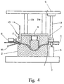
- Fig. 4 is a schematic sectional view of the embodiment, showing the completion of gluing.
- Fig. 5 is schematic sectional view of a conventional device, showing the state before an ornamental body is glued onto a shaped body;
- Fig. 6 shows a conventional device of Fig. 5 showing the state when the dies are partly closed.
- a lower die 2 is securely mounted on a lower surface plane 1.
- the upper surface of the lower die 2 is shaped such that it corresponds to a concave part B and a fitting groove M of a shaped body W.
- a plurality of upright elevating cylinders 3, 3 are disposed around the lower die on the lower surface plate (only one cylinder is shown in the drawing).
- the end portions of the rods of the cylinders support a receiving plate 4 above the lower die such that the receiving plate 4 is vertically movable.
- the receiving plate 4 has an opening 4A which is generally analogous to and slightly larger than the outline of the fitting groove M.
- a plurality of clampers 5, 5 are mounted on the receiving plate 4 at the periphery of the opening such that they are directed towards the opening 4A and surround it and such that they can move towards and away from the opening 4A and hold the ornamental body and apply a tension to it (refer to Japanese Utility Model Kokai Koho 6-36407).
- the upper die 7 has an outline, or outer periphery, which is generally analogous to and slightly smaller than the inner diameter of the fitting groove M.
- the upper die 7 at its central part has a pre-pressing member 7A which is suspended therefrom through a spring 8 such that the member 7A projects from the upper die 7 and can move vertically relative to the upper die 7.
- the member 7A has a lower surface which corresponds to the concave part B of the shaped body W.
- a plurality of pressing bars 9, 9 are disposed around the upper die 7.
- the bars 9, 9 are designed such that they come into contact with the receiving plate 4 before the upper die 7 contacts the shaped body W on the lower die 2 when the upper surface plate 6 is lowered, and such that the bars press the receiving plate 4 down against the pushing-up force of the elevating cylinders 3,3.
- Numerals 10 and 11 are respectively an annular heated cutter and fitting edge, both connected to cylinders (not shown). In the embodiment shown in the drawing, cylinders are used for lifting the receiving plate. They may be substituted by springs.
- a formed body W is placed on the lower die 2 so that it fits in it, and an ornamental body S is held by the clampers 5,5 at its periphery so that they apply a tension to the ornamental body.
- the upper surface plate 6 is lowered. Accordingly, first the pre-pressing member 7A begins to press the ornamental body S as in Fig. 2, and the clampers 5, 5 move towards the opening 7. The ornamental body S is preformed in a shape corresponding to the lower surface of the pre-pressing member 7A and lowered. As the downward movement of the upper surface plane 6 continues, the pressing bars 9,9 come into contact with the upper surface of the receiving plate 4, thereby lowering the plate 4 and the ornamental body S and finally pressing and gluing the ornamental body S onto the concave part B of the shape] body W, as in Fig. 3.
- the pre-pressing member 7A moves into the upper die 7 relative to it, and the upper die 7 and the receiving plate 4 move further down, while the clampers 5, 5 move towards the opening 4A. Accordingly, the ornamental body S is completely pressed against the formed body W and glued onto it as in Fig. 4, while the downward movement of the upper surface plate 6 stops.
- the heated cutter 10 is then lowered to trim any unnecessary part away from the body S, and a fitting edge 11 is lowered to fit the trimmed edge of the body S in the fitting groove M. Thus the process is completed.
- the downward movement of the upper die and movement of the receiving plate and clampers are phased, thereby preforming the ornamental body in the convex shape corresponding to that of the upper die, gluing the ornamental body onto the concave part of the shaped body first, and then gluing the other part.
- almost no residual stress is caused in the ornamental body glued on the shaped body, and a product of good quality is manufactured wherein there is no separation of the ornamental body from the shaped body.
Landscapes
- Engineering & Computer Science (AREA)
- Manufacturing & Machinery (AREA)
- Lining Or Joining Of Plastics Or The Like (AREA)
- Adornments (AREA)
Applications Claiming Priority (2)
| Application Number | Priority Date | Filing Date | Title |
|---|---|---|---|
| JP7100148A JPH08267592A (ja) | 1995-03-31 | 1995-03-31 | 加飾体貼着装置 |
| JP100148/95 | 1995-03-31 |
Publications (2)
| Publication Number | Publication Date |
|---|---|
| EP0734841A2 true EP0734841A2 (fr) | 1996-10-02 |
| EP0734841A3 EP0734841A3 (fr) | 1997-08-20 |
Family
ID=14266243
Family Applications (1)
| Application Number | Title | Priority Date | Filing Date |
|---|---|---|---|
| EP96104997A Withdrawn EP0734841A3 (fr) | 1995-03-31 | 1996-03-28 | Dispositif pour appliquer un revêtement décoratif |
Country Status (7)
| Country | Link |
|---|---|
| US (1) | US5711845A (fr) |
| EP (1) | EP0734841A3 (fr) |
| JP (1) | JPH08267592A (fr) |
| KR (1) | KR960033789A (fr) |
| CN (1) | CN1140658A (fr) |
| MY (1) | MY132242A (fr) |
| SG (1) | SG72647A1 (fr) |
Cited By (4)
| Publication number | Priority date | Publication date | Assignee | Title |
|---|---|---|---|---|
| DE10258891A1 (de) * | 2002-12-17 | 2004-07-01 | Bayerische Motoren Werke Ag | Verfahren zum Bespannen eines flächigen Interieur-Bauteils |
| DE102008009762A1 (de) * | 2008-02-19 | 2009-08-20 | Faurecia Innenraum Systeme Gmbh | Vorrichtung und Verfahren zum Kaschieren einer Trägerschicht mit einer Dekorschicht |
| EP2804729B1 (fr) | 2012-01-18 | 2016-04-06 | Dieffenbacher GmbH Maschinen- und Anlagenbau | Procédé et dispositif de fabrication d'une préforme tridimensionnelle à partir d'une structure fibreuse lors de la fabrication de pièces moulées renforcées par des fibres |
| CN112606376A (zh) * | 2020-12-04 | 2021-04-06 | 成都宏明双新科技股份有限公司 | 一种高精密胶膜贴膜设备 |
Families Citing this family (13)
| Publication number | Priority date | Publication date | Assignee | Title |
|---|---|---|---|---|
| DE19746867C1 (de) * | 1997-10-24 | 1999-04-08 | Fritsche Moellmann Gmbh Co Kg | Thermoformwerkzeug |
| US7866364B2 (en) * | 2006-04-28 | 2011-01-11 | Hewlett-Packard Development Company, L.P. | Fabrication tool for bonding |
| DE102009017361B4 (de) * | 2009-04-14 | 2013-03-28 | Airbus Operations Gmbh | Vorrichtung und Verfahren zum Drapieren von Fasergewirken für gekrümmte Profilstrukturteile aus Faserverbundmaterial |
| CN102525168A (zh) * | 2012-01-22 | 2012-07-04 | 无锡研中科技有限公司 | 座椅靠背包布机的3d包布张紧机构 |
| CN102525166B (zh) * | 2012-01-22 | 2014-07-16 | 无锡研中科技有限公司 | 座椅靠背包布机的3d包布压紧机构 |
| CN102525165B (zh) * | 2012-01-22 | 2014-04-16 | 无锡研中科技有限公司 | 座椅靠背包布机的托布机构 |
| US9305894B2 (en) * | 2013-06-05 | 2016-04-05 | Globalfoundries Inc. | Constrained die adhesion cure process |
| JP6372694B2 (ja) * | 2014-09-26 | 2018-08-15 | 豊田合成株式会社 | ホットスタンプ装置 |
| CN104586127B (zh) * | 2015-01-27 | 2017-05-17 | 安徽省佳艺休闲用品有限公司 | 一种应用于休闲椅背加工的压布机及其使用方法 |
| DE102018201850B4 (de) * | 2018-02-07 | 2026-04-23 | Bayerische Motoren Werke Aktiengesellschaft | Verfahren zum Kaschieren einer Oberseite eines Trägerbauteils mit einer Kaschiermateriallage und zugehörige Vorrichtung |
| CN109733669A (zh) * | 2018-12-23 | 2019-05-10 | 武汉抱冰工业发展有限公司 | 自动切覆膜设备及切覆膜一体包装方法 |
| CN111940605B (zh) * | 2020-08-04 | 2022-09-23 | 惠州融汇科技有限公司 | 新能源汽车电池箱体顶盖成型结构 |
| CN114193773B (zh) * | 2021-12-17 | 2024-06-04 | 全兴汽车配件(福州)有限公司 | 汽车立柱贴皮装置及其工作方法 |
Family Cites Families (9)
| Publication number | Priority date | Publication date | Assignee | Title |
|---|---|---|---|---|
| DK147173C (da) * | 1980-03-04 | 1984-11-05 | F O W O I Nybro Ab | Fremgangsmaade ved fremstilling af en polygonal finergenstand ved varmpresning |
| DE3338513A1 (de) * | 1983-10-22 | 1985-05-02 | Stanztechnik Gmbh R + S, 6000 Frankfurt | Verfahren und vorrichtung zum herstellen kaschierter teile |
| US5076880A (en) * | 1988-09-16 | 1991-12-31 | R + S Stanztechnik Gmbh | Apparatus for manufacturing trim panels including several trim components |
| US4908084A (en) * | 1988-11-18 | 1990-03-13 | Kenneth Assink | Substrate convering method and apparatus |
| US5032206A (en) * | 1988-12-23 | 1991-07-16 | Vti Veneer Technology | Apparatus and method for applying an overlay to a curved surface |
| JP2878528B2 (ja) * | 1992-07-21 | 1999-04-05 | 株式会社日立製作所 | 磁気記録再生装置 |
| US5324384A (en) * | 1992-12-23 | 1994-06-28 | R & S Stanztechnik Gmbh | Apparatus for laminating a trim panel and folding a brim around the panel rim |
| IT1262281B (it) * | 1993-06-16 | 1996-06-19 | Processo e stampo di termoformatura per stampare un articolo che presenta almeno una zona fortemente deformata. | |
| US5494546A (en) * | 1994-02-18 | 1996-02-27 | Horvath; Steven J. | Apparatus and method for applying anti-lacerative film to glass |
-
1995
- 1995-03-31 JP JP7100148A patent/JPH08267592A/ja active Pending
-
1996
- 1996-03-28 US US08/624,978 patent/US5711845A/en not_active Expired - Fee Related
- 1996-03-28 EP EP96104997A patent/EP0734841A3/fr not_active Withdrawn
- 1996-03-29 MY MYPI96001187A patent/MY132242A/en unknown
- 1996-03-29 KR KR1019960009021A patent/KR960033789A/ko not_active Ceased
- 1996-03-29 CN CN96108066A patent/CN1140658A/zh active Pending
- 1996-03-30 SG SG1996006286A patent/SG72647A1/en unknown
Cited By (6)
| Publication number | Priority date | Publication date | Assignee | Title |
|---|---|---|---|---|
| DE10258891A1 (de) * | 2002-12-17 | 2004-07-01 | Bayerische Motoren Werke Ag | Verfahren zum Bespannen eines flächigen Interieur-Bauteils |
| DE102008009762A1 (de) * | 2008-02-19 | 2009-08-20 | Faurecia Innenraum Systeme Gmbh | Vorrichtung und Verfahren zum Kaschieren einer Trägerschicht mit einer Dekorschicht |
| WO2009103541A1 (fr) | 2008-02-19 | 2009-08-27 | Faurecia Innenraum Systeme Gmbh | Dispositif et procédé de doublage d’une couche support avec une couche décorative |
| US9302422B2 (en) | 2008-02-19 | 2016-04-05 | Faurecia Innenraum Systeme Gmbh | Device and method for laminating a substrate layer with a decorative layer |
| EP2804729B1 (fr) | 2012-01-18 | 2016-04-06 | Dieffenbacher GmbH Maschinen- und Anlagenbau | Procédé et dispositif de fabrication d'une préforme tridimensionnelle à partir d'une structure fibreuse lors de la fabrication de pièces moulées renforcées par des fibres |
| CN112606376A (zh) * | 2020-12-04 | 2021-04-06 | 成都宏明双新科技股份有限公司 | 一种高精密胶膜贴膜设备 |
Also Published As
| Publication number | Publication date |
|---|---|
| CN1140658A (zh) | 1997-01-22 |
| US5711845A (en) | 1998-01-27 |
| EP0734841A3 (fr) | 1997-08-20 |
| MY132242A (en) | 2007-09-28 |
| SG72647A1 (en) | 2000-05-23 |
| KR960033789A (ko) | 1996-10-22 |
| JPH08267592A (ja) | 1996-10-15 |
Similar Documents
| Publication | Publication Date | Title |
|---|---|---|
| US5711845A (en) | Device for gluing an ornamental body | |
| CA2006773A1 (fr) | Appareil et methode pour emboutir la tole a l'aide d'un poincon sur piston | |
| JPH08318570A (ja) | 真空成形同時巻込トリミング装置 | |
| JP2680905B2 (ja) | 薄板材をプレス加工するための装置 | |
| US4818331A (en) | Apparatus for manufacturing a seat | |
| JP3508911B2 (ja) | プレス成形における原反シートのチャッキング方法及びチャキング装置 | |
| JP3189969B2 (ja) | 加飾体貼着木目込み方法及びその装置 | |
| KR100421303B1 (ko) | 장식용몸체접착장치내의주형변형장치 | |
| JPH06206258A (ja) | 圧着装置 | |
| JPH1177815A (ja) | 積層成形体の成形装置 | |
| JP2633311B2 (ja) | ヒンジフレームを有する積層体の成形方法 | |
| JP3745660B2 (ja) | 接着シートの製造装置 | |
| JP2633310B2 (ja) | 積層体成形装置 | |
| JPH058301A (ja) | 自動車用内装部品の製造方法 | |
| CN218744450U (zh) | 一种座圈铝箔加热器压接装置 | |
| CN218053945U (zh) | 一种用于热压模具的脱料装置 | |
| JP2787663B2 (ja) | トレイ型マットの成形方法及びトレイ型マット用成形機 | |
| JP2588964Y2 (ja) | シートのトリムカバー接着装置 | |
| JPH0360305B2 (fr) | ||
| JPH05321Y2 (fr) | ||
| JPH0911336A (ja) | 加飾体貼着装置 | |
| JP2578875Y2 (ja) | クロスの圧着装置 | |
| KR900004101Y1 (ko) | 프레스기의 복합 금형 장치 | |
| JP2765775B2 (ja) | 自動車用内装部品における装飾シートの圧着方法および圧着装置 | |
| JPH0387243A (ja) | 薄膜貼り込み装置 |
Legal Events
| Date | Code | Title | Description |
|---|---|---|---|
| PUAI | Public reference made under article 153(3) epc to a published international application that has entered the european phase |
Free format text: ORIGINAL CODE: 0009012 |
|
| AK | Designated contracting states |
Kind code of ref document: A2 Designated state(s): CH DE FR GB IT LI |
|
| PUAL | Search report despatched |
Free format text: ORIGINAL CODE: 0009013 |
|
| AK | Designated contracting states |
Kind code of ref document: A3 Designated state(s): CH DE FR GB IT LI |
|
| 17P | Request for examination filed |
Effective date: 19980109 |
|
| 17Q | First examination report despatched |
Effective date: 19980619 |
|
| STAA | Information on the status of an ep patent application or granted ep patent |
Free format text: STATUS: THE APPLICATION HAS BEEN WITHDRAWN |
|
| 18W | Application withdrawn |
Withdrawal date: 19990728 |