EP0734997B1 - Wagenheber - Google Patents
Wagenheber Download PDFInfo
- Publication number
- EP0734997B1 EP0734997B1 EP19960400686 EP96400686A EP0734997B1 EP 0734997 B1 EP0734997 B1 EP 0734997B1 EP 19960400686 EP19960400686 EP 19960400686 EP 96400686 A EP96400686 A EP 96400686A EP 0734997 B1 EP0734997 B1 EP 0734997B1
- Authority
- EP
- European Patent Office
- Prior art keywords
- jack
- axis
- head
- nut
- lifting arm
- Prior art date
- Legal status (The legal status is an assumption and is not a legal conclusion. Google has not performed a legal analysis and makes no representation as to the accuracy of the status listed.)
- Expired - Lifetime
Links
- 230000000717 retained effect Effects 0.000 claims description 2
- 238000002955 isolation Methods 0.000 description 3
- 239000002184 metal Substances 0.000 description 3
- 229910052751 metal Inorganic materials 0.000 description 3
- 238000005452 bending Methods 0.000 description 2
- 238000006073 displacement reaction Methods 0.000 description 2
- 239000000463 material Substances 0.000 description 2
- 230000000284 resting effect Effects 0.000 description 2
- 239000011324 bead Substances 0.000 description 1
- 230000006835 compression Effects 0.000 description 1
- 238000007906 compression Methods 0.000 description 1
- 238000010276 construction Methods 0.000 description 1
- 230000007423 decrease Effects 0.000 description 1
- 230000014759 maintenance of location Effects 0.000 description 1
- 125000006850 spacer group Chemical group 0.000 description 1
Images






Classifications
-
- B—PERFORMING OPERATIONS; TRANSPORTING
- B66—HOISTING; LIFTING; HAULING
- B66F—HOISTING, LIFTING, HAULING OR PUSHING, NOT OTHERWISE PROVIDED FOR, e.g. DEVICES WHICH APPLY A LIFTING OR PUSHING FORCE DIRECTLY TO THE SURFACE OF A LOAD
- B66F3/00—Devices, e.g. jacks, adapted for uninterrupted lifting of loads
- B66F3/08—Devices, e.g. jacks, adapted for uninterrupted lifting of loads screw operated
- B66F3/12—Devices, e.g. jacks, adapted for uninterrupted lifting of loads screw operated comprising toggle levers
Definitions
- the present invention relates to a vehicle jack comprising a supporting leg and a lifting arm mounted at pivoting at one end on the latter, provided at the other end of a head to be engaged under the vehicle to be lifted, a screw control to move the lifting arm, connecting it and the supporting leg, turning in a nut-shaped part mounted at pivoting on the supporting leg and connected at one end to the arm of lifting, the jack head being arranged in alignment with the lifting screw ordered.
- An object of the present invention is to provide a jack improved simplified construction.
- the jack head has a surface portion cylindrical against which the end of the screw is in axial support at during the jack operation, allowing the movement of the screw.
- the jack head is articulated on the arm of lifting around an axis of rotation cutting perpendicularly the longitudinal axis of the control screw, said cylindrical surface portion being of revolution around this axis of rotation.
- control screw has a head shouldered resting axially on a thrust ball bearing at least during jack operation when the jack is loaded.
- the thrust ball is housed in a yoke articulated on the lifting arm.
- the yoke is articulated on the lifting arm around the same axis of rotation as the jack head.
- the nut-forming part being received in supporting leg recesses, the nut-forming part is retained in these by a retaining element integral with this last and engaged in at least one curvilinear lumen of the leg support.
- the jack 1 shown in the figures has a support leg 2 intended to rest, by a lower end forming a foot 3, on floor.
- a lifting arm 4 is articulated at one end on this leg support 2, and supports at the other end a head 5 intended to come on contact with the vehicle to be lifted.
- the lifting arm 4 is articulated on the supporting leg 2 around an axis of rotation X perpendicular to the plane of Figure 1.
- the head 5 of the jack 1 is articulated on the lifting arm 4 around an axis of rotation Y parallel to the X axis.
- the control screw 6 extends in a longitudinal axis W parallel to the plane of Figure 1, intersecting perpendicularly the X axis. It crosses a piece forming a nut 8 articulated on the supporting leg 2 around an axis of rotation Z intersecting the W axis and parallel to the X axis.
- the jack 1 is symmetrical by relation to a plane of symmetry containing the axis W and perpendicular to the X axis.
- the head 5 of the jack 1 is shown in isolation in FIGS. 3 to 5. It is preferably made of plastic, and includes a body 50 crossed by a cylindrical bore 51 of revolution around of the Y axis, for the passage of a pivot pin 98 of the head 5 on the lifting arm 4.
- Two fingers 52, 53 extend upper body 50 (when the jack is in the deployed position lifting a vehicle as shown in Figure 1) and define between them a groove 54, opening upwards, for the engagement of the head 5 on a weld bead or a rebate of the vehicle body, projecting downward, or over any other part of the vehicle provided for this purpose.
- Surfaces 540, 541 respective fingers 52, 53, facing each other, are flat and parallel.
- the head 5 has stop surfaces 520, whose role will be specified below, located at the base of finger 52 and extending, planes, at an angle of 44 ° 30 'with the plane of the surfaces 540 and 541. The lower ends of these surfaces have been referenced 521 stop 520.
- the body 50 also has a surface portion 55, cylindrical of revolution around the Y axis, extending over a sector angular of 60 °.
- the control screw 6 has a helical thread 60 extending along the axis W, engaged in the piece forming a nut 8, and has at one axial end a shouldered head 61. It is provided at the opposite axial end of a tip 66 on which the handle 7, about an axis of rotation cutting perpendicularly the W axis.
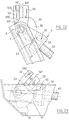
- the shouldered head 61 rests by its axial end edge 63 against the surface portion 55 of the head 5 and by its shoulder, referenced 64, on a ball stop 62 bearing on a yoke 9.
- This stop at balls 62 comprises, in a manner known per se, two rings 62a, 62b of axis W, defining raceways for balls 62c interposed between the rings 62a, 62b.
- the yoke 9 is shown in isolation in Figures 6 to 8. It has two flanges 90, planes and parallel to each other, joined by a base 91. The latter extends perpendicular to the plane of the flanges 90. Holes 92 of axis Y are provided on the flanges 90 for the passage of the aforementioned hinge pin 98, and the rotational mounting of the yoke 9 on the lifting arm 4 around the Y axis.
- the base 91 is crossed by a bore 93 for the passage of the control screw 6.
- the ring 62b of the ball bearing 62 rests against the face 910 of the base 91 facing the interior space at flanges 90. These are perforated in 94 as shown in the Figure 8 to save material.
- edges 95 are present, observed in the direction of the Y axis, a generally triangular contour, laterally delimited by two straight edges 95 converging in approximation of the Y axis, these edges 95 being joined at their end opposite the base 91 by an edge 96 in an arc, centered on the axis Y, and connecting to the base 91 by straight edges 97, parallel to the W axis.
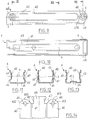
- FIGS. 9 to 14 show the arms of lifting 4.
- the latter is preferably produced by stamping, cutting and bending a sheet to form a metal profile elongated in the direction of a longitudinal axis V perpendicular to the X and Y axes.
- This profile has a cross section having the general shape of a U, as shown more particularly on Figures 11 to 13. It has two wings 40 joined by a back 41 generally extending perpendicular to the wings 40.
- Des oblong recesses 42 from stamping extend parallel to the axis V on the wings 40 to stiffen the profile. These recesses 42 protrude into the interior space of the profile located between the wings 40.
- An oblong recess 43, projecting inward, is made on the back 41 for the same purpose.
- Wings 40 are drilled at a longitudinal end, at 44, for the passage the aforementioned pin 98 and the rotational assembly of the head 5, of the yoke 9 and the lifting arm 4. These holes 44 are made at a longitudinal end of the recesses 42.
- the wings 40 are drilled at the opposite longitudinal end, at 46, for the passage a pin 28 of axis X used for the articulation of the lifting arm 4 on the supporting leg 2.
- These holes 46 are made on circular stampings 47 projecting towards the outside of the profile, as shown more particularly in Figure 12. These stampings circulars 47 are located in the extension of the recesses 42, sparing an interval 470 with these as shown on the Figure 9.
- the back 41 is extended, at the end of the lifting arm 4 articulated on the support leg 2, by a wall 48 extending obliquely between the wings 40 and forming a spacer.
- the wall 48 results from cutting and bending the sheet metal used to make the profile, as illustrated in figure 14.
- the ends longitudinal wings 40 have at the end hinged on the supporting leg 2 a generally triangular profile, observed in the direction of the X axis. This profile is delimited by two edges orthogonal rectilinear 401, 402 joined by an edge in an arc 403 centered on the X axis. After folding, the wall 48 extends in the plane edges 401 and forms with the back 41 a corner dihedral at the top 238 °.
- Figures 15 to 19 show the piece in isolation forming nut 8.
- the latter is preferably made of material plastic. It comprises a body 80 crossed along the axis W by a internal thread 81 adapted to receive the threaded body 60 of the screw control 6. Side portions 82 form a protrusion on the other of the body 80 for the articulation of the part forming the nut 8 on the supporting leg 2.
- These lateral parts 82 are delimited radially, on the outside, by cylindrical surfaces of revolution around the Z axis, and axially by end edges 83 planes and perpendicular to the Z axis.
- the nut-forming part 8 also has two legs 84 crossed by holes 85 T axis parallel to Z axis, for mounting the nut forming part 8 on the supporting leg 2, as will be specified later.
- the legs 84 are connected to the body 80 in providing with the cylindrical surfaces 82 of the annular grooves 86 centered on the Z axis.
- the top dihedral Z axis delimited by the plane perpendicular to the W axis and by the plane containing the T axis, is of angle at the top 60 °.
- Figures 24 to 29 show the leg separately support 2.
- the latter is preferably produced by stamping, cutting and folding of a sheet to form an elongated profile according to a longitudinal axis G perpendicular to the axis Z.
- This profile has a cross section having the general shape of a U, comprising two wings 20 joined by a back 21.
- Each wing 20 has a oblong recess 22 coming from stamping, projecting into the interior space of the profile located between the wings 20, and intended to stiffen the profile.
- the foot 3 is formed by cutting and folding as illustrated in Figure 29. More specifically, the foot 3 has a first wall plane 30 connecting to the back 21 by a fold line 31 and forming, in assembled jack position, an angle of 43 ° with the back 21 as shown in FIG. 24.
- This wall 30 is extended downwards by a flat wall 32 intended to serve as a bearing surface On the ground.
- the fold line extending to the junction of the walls 30 and 32.
- the dihedron having for top the line of folding 33 and delimited by the planes of the walls 30 and 32 at an angle to summit of 142 °.
- the wall 30 widens away from the back 21 until reaching a width approximately double that of the back 21 to level of the fold line 33.
- the width of the wall 32 is constant. The latter rests, by its face opposite to that coming resting on the ground, against the edge of the wings 20.
- the free edges 23 of the wings 20 are curved outwards as shown more particularly on the sections transverse of Figures 27 and 28, for the purpose of stiffening the streamlined.
- the cross section of the supporting leg 2 is generally constant from foot 3 to about half of the height of the supporting leg 2, where the width of the wings 20 increases and becomes maximum at the level of a bore 24 serving for the passage of the pivot pin 28 of the lifting arm 4.
- the width of the wings 20 then decreases to the height of the ends longitudinal upper 26 of the recesses 22, where the wings 20 form notches 211.
- the back 21 is interrupted at the height of these notches 211.
- the width of the wings 20 increases above the notches 211 towards the upper end of the leg support 2, located opposite foot 3, to recesses 25 formed on the wings 20, serving as articulation bearings around the Z axis to the nut-forming part 8.
- recesses 25 formed on the wings 20, serving as articulation bearings around the Z axis to the nut-forming part 8.
- curvilinear lights 27 are formed on the portion of the wings 20 extending between the upper ends 26 of the recesses oblong 22 and the plane containing the Z axis and perpendicular to the axis longitudinal G.
- the back 21 forms, at the height of the holes 24, a dihedral projecting outwards, from angle to summit 152 °.
- edges 23 extend straight, parallel to the recesses 22, from their lower end bearing against the wall 32 to plane containing the Z axis and perpendicular to the G axis.
- the edges 23 are extend beyond this plane in arcs of circle 230 and end with rectilinear portions 231 perpendicular to the axis G.
- the recesses 25 have, as shown in the figure 24, edges in the shape of a semicircle 250, centered on the axis Z and of radius adapted to that of the cylindrical surfaces 82. These semicircular edges 250 are extended below by edges rectilinear 251 perpendicular to the longitudinal axis G, and superiorly, by straight edges 252 extending parallel to the edges 251 but over a distance corresponding to about a quarter of the length of the straight edges 251. The edges 250, 251 and 252 are bent towards the interior space located between the wings 20 to form bearing surfaces 253 coming into contact cylindrical surfaces 82 of the nut-forming part 8. These surfaces with a span of 253 are generatrix parallel to the Z axis. 25 define grooves whose bottom consists of the edges semicircular 250 and whose opening width, that is to say the distance between the straight edges 251 and 252, is at least equal at the diameter of the semicircular edges 250.
- Each curvilinear lumen 27 extends along a median line K in an arc located at the same distance from the Z axis as the distance separating the latter and the axis T of the holes 85, and presents at its longitudinal ends of the semi-circular edges 270 and 271.
- the dihedral having for its summit the Z axis, delimited by the planes containing the axes of the semicircular edges 270 and 271, is of angle at the top 115 °.
- the plane containing the Z axis and the axis of the semi-circular holes 270 extends parallel to the straight edges 251.
- the mounting of the nut-forming part 8 on the support leg 2 is easily carried out by engaging the nut-forming part 8 provided with the control screw 6 in the recesses 25, until the cylindrical surfaces 82 against the semicircular edges 250.
- the introduction of the nut-forming part 8 can be carried out by a simple translational movement in a perpendicular direction to the Z axis and suitable for mechanized execution.
- the 85 holes tabs 84 of the nut forming part 8 are then positioned in gaze of the curvilinear lights 27.
- a rivet 89 is introduced into the curvilinear lights 27 and 85 holes to hold the part forming nut 8 on the support leg 2. After the riveting operation, the rivet 89 comes to bear axially at its axial ends on the external surface 200 of the wings 20 bordering the curved lights 27.
- the operation of jack 1 is as follows.
- the lifting arm 4 folds down between the wings 20 of the supporting leg 2, the head 5 abutting by the stop surfaces 520 on the edges curved 23.
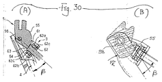
- the edge end 63 of the control screw 6 rests on the end of the cylindrical surface portion 55 adjacent to the finger 53, as shown more particularly in Figure 23.
- the handle 7 can advantageously fall back against the outer surface of a wing 20 as shown on Figure 21.
- the rivet 89 abuts against the semicircular edges 271.
- the user turns the handle 7 and rotates the control screw 6 around the axis W.
- the longitudinal displacement of the control screw 6 which results from its rotation in the internal thread 81 causes the pivoting arm to pivot lifting 4 clockwise in Figure 1 and moving to the top of the head 5.
- the rotation of the lifting arm 4 is accompanied by a displacement of the rivet 89 in the curved lights 27 until stop of the latter against the semi-circular edges 270.
- the jack 1 is then in its maximum lifting position and the control screw is subjected to tensile forces when the jack is loaded.
- the surfaces 540 and 541 are normally oriented vertically in the vehicle lifting position, as shown in FIG.
- the user turns the control screw 6.
- the control screw 6 works in traction and the thrust ball 62 is axially stressed in compression.
- the control screw 6 comes to bear axially by the end edge 63 against the surface portion 55 of the head 5. It is ensured thus driving the lifting arm, without using a sheath engaged on the control screw as is the case on the known jacks.
- a jack according to the invention has a space requirement in the folded position sufficiently small for its housing in a spare wheel rim, in particular thanks to the particular arrangement of the control screw 6 on the jack 1.
- Jack assembly is easy and can be performed by a robot.
- the positioning of the axes of rotation X, Y and Z, in particular the intersection of the W and Y axes is advantageous from the point of kinematic view.
- Rivet 89 increases the safety of using the jack preventing the wings of the support leg 2 from moving apart.
- a stop sleeve is not necessary and the free rotation of the head 5 on the lifting arm 4 reduces the risk of damage to the vehicle body in case of improper positioning of the jack.
Landscapes
- Life Sciences & Earth Sciences (AREA)
- Engineering & Computer Science (AREA)
- Geology (AREA)
- Mechanical Engineering (AREA)
- Structural Engineering (AREA)
- Vehicle Cleaning, Maintenance, Repair, Refitting, And Outriggers (AREA)
Claims (9)
- Wagenheber (1) umfassend ein Stützbein (2) und einen Hebearm (4), der an einem Ende drehbar an jenem montiert ist, und am anderen Ende einen Kopf (5) aufweist, um zum Anheben unter den Wagen zu greifen, wobei sich eine Betätigungsschraube (6) zum Bewegen des Hebearms (4), welche diesen und das Stützbein verbindet, in einem eine Mutter bildenden Teil dreht, welches schwenkbar am Stützbein montiert ist und an einem Ende am Hebearm (4) befestigt ist, wobei der Kopf (5) des Hebers in Ausrichtung mit der Betätigungsschraube (6) angeordnet ist, dadurch gekennzeichnet, daß der Kopf einen zylindrischen Oberflächenabschnitt (55) aufweist, gegen welchen sich das Ende (63) der Schraube bei der Betätigung des Hebers axial abstützt, wobei das Ausschlagen der Schraube ermöglicht ist.
- Heber gemäß Anspruch 1, dadurch gekennzeichnet, daß der Hebekopf (5) am Hebearm (4) um eine Rotationsachse (Y) schwenkbar ist, welche die Längsachse (W) der Betätigungsschraube (6) senkrecht schneidet, und daß der zylindrische Oberflächenabschnitt (55) drehbar um diese Rotationsachse (Y) ist.
- Heber gemäß einem der Ansprüche 1 und 2, dadurch gekennzeichnet, daß die Betätigungsschraube einen Kopf mit einem Ansatz aufweist, wobei sich der Ansatz (64) zumindest dann beim Betrieb des Hebers, wenn der Heber belastet ist, an einem Kugellager (62) abstützt.
- Heber gemäß den Ansprüchen 2 und 3, dadurch gekennzeichnet, daß das Kugellager (62) in einer Kappe (9) angeordnet ist, die am Hebearm schwenkbar ist.
- Heber gemäß Anspruch 4, dadurch gekennzeichnet, daß die Kappe am Hebearm um die selbe Rotationsachse (Y) schwenkbar ist, wie der Hebekopf.
- Heber gemäß einem der Ansprüche 1 bis 5, wobei das die Mutter bildende Teil (8) in Aussparungen (25) des Stützbeins (2) gelagert ist, dadurch gekennzeichnet, daß das die Mutter bildende Teil in diesen von einem Halteelement (89) gehalten wird, welches mit dem die Mutter bildenden Teil verbunden ist, und in mindestens eine gekrümmte Öffnung (27) des Stützbeins (2) eingreift.
- Heber gemäß Anspruch 6, dadurch gekennzeichnet, daß jede Aussparung (25) des Stützbeins (2), in welcher das die Mutter bildende Teil (8) gelagert ist, eine Vertiefung ausbildet, deren Boden von einem halbkreisförmigen Rand (250) begrenzt ist, und deren Öffnungsgröße größer oder gleich ist wie der Durchmesser des halbkreisförmigen Rands.
- Heber gemäß Anspruch 7, wobei das Stützbein (2) im wesentlichen die Form eines Profils mit U-förmigem Querschnitt hat, dadurch gekennzeichnet, daß das Halteelement ein Niet (89) ist, der sich axial an den Außenseiten der zwei Flügel (20) des Profils abstützt.
- Heber gemäß Anspruch 8, wobei das Stützbein (2) im wesentlichen die Form eines Profils mit U-förmigem Querschnitt hat, dadurch gekennzeichnet, daß die Wand der Flügel des Profils, welche die Aussparungen (25) begrenzt, gekrümmt ist, um die Stützfläche zu vergrößern, die das die Mutter bildende Teil (8) berührt.
Applications Claiming Priority (2)
| Application Number | Priority Date | Filing Date | Title |
|---|---|---|---|
| FR9503831A FR2732324B1 (fr) | 1995-03-31 | 1995-03-31 | Cric de vehicule |
| FR9503831 | 1995-03-31 |
Publications (2)
| Publication Number | Publication Date |
|---|---|
| EP0734997A1 EP0734997A1 (de) | 1996-10-02 |
| EP0734997B1 true EP0734997B1 (de) | 2000-05-31 |
Family
ID=9477633
Family Applications (1)
| Application Number | Title | Priority Date | Filing Date |
|---|---|---|---|
| EP19960400686 Expired - Lifetime EP0734997B1 (de) | 1995-03-31 | 1996-03-29 | Wagenheber |
Country Status (3)
| Country | Link |
|---|---|
| EP (1) | EP0734997B1 (de) |
| DE (1) | DE69608604D1 (de) |
| FR (1) | FR2732324B1 (de) |
Families Citing this family (3)
| Publication number | Priority date | Publication date | Assignee | Title |
|---|---|---|---|---|
| ES2130961B1 (es) * | 1996-09-27 | 2000-03-01 | Batz S Coop Ltda | Gato para vehiculos. |
| FR2759688B1 (fr) * | 1997-02-18 | 1999-05-07 | Adwest Bowden France Sa | Cric de voiture de type y |
| ES2143920B1 (es) * | 1997-06-19 | 2000-12-16 | Batz S Coop Ltda | Gato ligero. |
Family Cites Families (4)
| Publication number | Priority date | Publication date | Assignee | Title |
|---|---|---|---|---|
| DE2756108C2 (de) * | 1977-12-16 | 1984-05-30 | E.A. Storz Gmbh & Co Kg, 7200 Tuttlingen | Wagenheber |
| DE3037934A1 (de) * | 1980-10-08 | 1982-05-13 | E.A. Storz Gmbh & Co Kg, 7200 Tuttlingen | Wagenheber |
| GB2136393B (en) * | 1983-02-26 | 1986-01-22 | Metallifacture Ltd | Vehicle jack |
| ES2108736T5 (es) * | 1992-04-14 | 2000-11-01 | E P I Europ De Participations | Gato para vehiculos. |
-
1995
- 1995-03-31 FR FR9503831A patent/FR2732324B1/fr not_active Expired - Fee Related
-
1996
- 1996-03-29 EP EP19960400686 patent/EP0734997B1/de not_active Expired - Lifetime
- 1996-03-29 DE DE69608604T patent/DE69608604D1/de not_active Expired - Lifetime
Also Published As
| Publication number | Publication date |
|---|---|
| DE69608604D1 (de) | 2000-07-06 |
| FR2732324B1 (fr) | 1997-06-20 |
| FR2732324A1 (fr) | 1996-10-04 |
| EP0734997A1 (de) | 1996-10-02 |
Similar Documents
| Publication | Publication Date | Title |
|---|---|---|
| EP0545755B1 (de) | Spender für einen, eine pastöse Masse enthaltenden, Behälter | |
| EP3233617B1 (de) | Zusammenklappbarer tretroller | |
| EP0427584A1 (de) | Befestigungseinrichtung eines schlauchförmigen Organs, insbesondere einer Kraftfahrzeuglenksäule | |
| FR2627242A2 (fr) | Liaison rapide entre deux arbres ou analogues | |
| EP0013233B1 (de) | Gestell für einen Kinderstuhl | |
| CA3004993C (fr) | Tire-bouchon a levier | |
| EP0734997B1 (de) | Wagenheber | |
| WO1992022481A1 (fr) | Conteneur a bequilles escamotables dans les longerons lateraux | |
| EP0734996B1 (de) | Leicht montierbarer Wagenheber | |
| EP0169091B1 (de) | Teleskopische Kreuzgelenke | |
| EP0201424B1 (de) | Stuhl für Behinderte mit Vorrichtung zum schnellen Arretieren der Fussstützen | |
| FR2637949A1 (fr) | Dispositif de blocage axial d'un organe telescopique tel qu'une colonne de direction de vehicule automobile | |
| EP1381524B1 (de) | Vorrichtung zur verbesserung der manövrierfähigkeit eines transportwagens | |
| FR2918654A1 (fr) | Structure roulante repliable de support d'un rouleau rotatif sur lequel peut etre enroulee une bache. | |
| CH675053A5 (de) | ||
| WO2016027018A1 (fr) | Vehicule a roulettes de type trottinette | |
| EP0380890B1 (de) | Wagenheber mit doppelter Hebeschere | |
| FR3047693A1 (fr) | Roue pliable | |
| WO1981000235A1 (fr) | Bras d'essuie-glace soumis a l'action d'un ressort en compression | |
| EP2714500B1 (de) | Radfahrzeug in form eines rollers | |
| FR2565176A1 (fr) | Tablette de rangement de vehicule reliee par un ou plusieurs liens souples au panneau d'acces arriere de ce vehicule | |
| EP0636572A1 (de) | Hebebock, insbesondere Wagenheber | |
| FR2561725A1 (fr) | Systeme d'assemblage a articulation et application pour realiser des tables ou etageres repliables | |
| FR2709718A1 (fr) | Dispositif de commande de frein de stationnement à démultiplication de l'effort. | |
| LU85918A1 (fr) | Chaise pliante a dossier se rabattant sur le siege,l'un et l'autre se rabattant conjointement sur les pieds rapproches entre eux |
Legal Events
| Date | Code | Title | Description |
|---|---|---|---|
| PUAI | Public reference made under article 153(3) epc to a published international application that has entered the european phase |
Free format text: ORIGINAL CODE: 0009012 |
|
| AK | Designated contracting states |
Kind code of ref document: A1 Designated state(s): BE DE ES FR GB IT NL PT |
|
| RIN1 | Information on inventor provided before grant (corrected) |
Inventor name: FRAMBOISIER, DAVID Inventor name: TATE, JEAN-JACQUES Inventor name: FIGUERAS, BERNARD Inventor name: RUFFIE, GILLES |
|
| 17P | Request for examination filed |
Effective date: 19970324 |
|
| GRAG | Despatch of communication of intention to grant |
Free format text: ORIGINAL CODE: EPIDOS AGRA |
|
| 17Q | First examination report despatched |
Effective date: 19990701 |
|
| GRAG | Despatch of communication of intention to grant |
Free format text: ORIGINAL CODE: EPIDOS AGRA |
|
| GRAH | Despatch of communication of intention to grant a patent |
Free format text: ORIGINAL CODE: EPIDOS IGRA |
|
| GRAH | Despatch of communication of intention to grant a patent |
Free format text: ORIGINAL CODE: EPIDOS IGRA |
|
| GRAA | (expected) grant |
Free format text: ORIGINAL CODE: 0009210 |
|
| AK | Designated contracting states |
Kind code of ref document: B1 Designated state(s): BE DE ES FR GB IT NL PT |
|
| PG25 | Lapsed in a contracting state [announced via postgrant information from national office to epo] |
Ref country code: NL Free format text: LAPSE BECAUSE OF FAILURE TO SUBMIT A TRANSLATION OF THE DESCRIPTION OR TO PAY THE FEE WITHIN THE PRESCRIBED TIME-LIMIT Effective date: 20000531 Ref country code: IT Free format text: LAPSE BECAUSE OF FAILURE TO SUBMIT A TRANSLATION OF THE DESCRIPTION OR TO PAY THE FEE WITHIN THE PRE;WARNING: LAPSES OF ITALIAN PATENTS WITH EFFECTIVE DATE BEFORE 2007 MAY HAVE OCCURRED AT ANY TIME BEFORE 2007. THE CORRECT EFFECTIVE DATE MAY BE DIFFERENT FROM THE ONE RECORDED.SCRIBED TIME-LIMIT Effective date: 20000531 Ref country code: GB Free format text: LAPSE BECAUSE OF FAILURE TO SUBMIT A TRANSLATION OF THE DESCRIPTION OR TO PAY THE FEE WITHIN THE PRESCRIBED TIME-LIMIT Effective date: 20000531 Ref country code: ES Free format text: THE PATENT HAS BEEN ANNULLED BY A DECISION OF A NATIONAL AUTHORITY Effective date: 20000531 |
|
| REF | Corresponds to: |
Ref document number: 69608604 Country of ref document: DE Date of ref document: 20000706 |
|
| PG25 | Lapsed in a contracting state [announced via postgrant information from national office to epo] |
Ref country code: PT Free format text: LAPSE BECAUSE OF FAILURE TO SUBMIT A TRANSLATION OF THE DESCRIPTION OR TO PAY THE FEE WITHIN THE PRESCRIBED TIME-LIMIT Effective date: 20000831 |
|
| PG25 | Lapsed in a contracting state [announced via postgrant information from national office to epo] |
Ref country code: DE Free format text: LAPSE BECAUSE OF FAILURE TO SUBMIT A TRANSLATION OF THE DESCRIPTION OR TO PAY THE FEE WITHIN THE PRESCRIBED TIME-LIMIT Effective date: 20000901 |
|
| NLV1 | Nl: lapsed or annulled due to failure to fulfill the requirements of art. 29p and 29m of the patents act | ||
| GBV | Gb: ep patent (uk) treated as always having been void in accordance with gb section 77(7)/1977 [no translation filed] |
Effective date: 20000531 |
|
| PLBE | No opposition filed within time limit |
Free format text: ORIGINAL CODE: 0009261 |
|
| STAA | Information on the status of an ep patent application or granted ep patent |
Free format text: STATUS: NO OPPOSITION FILED WITHIN TIME LIMIT |
|
| PG25 | Lapsed in a contracting state [announced via postgrant information from national office to epo] |
Ref country code: BE Free format text: LAPSE BECAUSE OF NON-PAYMENT OF DUE FEES Effective date: 20010331 |
|
| 26N | No opposition filed | ||
| BERE | Be: lapsed |
Owner name: S.A. BOWDEN FRANCE Effective date: 20010331 |
|
| REG | Reference to a national code |
Ref country code: FR Ref legal event code: PLFP Year of fee payment: 20 |
|
| PGFP | Annual fee paid to national office [announced via postgrant information from national office to epo] |
Ref country code: FR Payment date: 20150317 Year of fee payment: 20 |