EP0735174A2 - Aguille à clapet pour des machines de fabrication de tricot - Google Patents
Aguille à clapet pour des machines de fabrication de tricot Download PDFInfo
- Publication number
- EP0735174A2 EP0735174A2 EP96103544A EP96103544A EP0735174A2 EP 0735174 A2 EP0735174 A2 EP 0735174A2 EP 96103544 A EP96103544 A EP 96103544A EP 96103544 A EP96103544 A EP 96103544A EP 0735174 A2 EP0735174 A2 EP 0735174A2
- Authority
- EP
- European Patent Office
- Prior art keywords
- tongue
- needle
- slot
- slot part
- shaft
- Prior art date
- Legal status (The legal status is an assumption and is not a legal conclusion. Google has not performed a legal analysis and makes no representation as to the accuracy of the status listed.)
- Granted
Links
- 238000004519 manufacturing process Methods 0.000 claims abstract description 4
- 230000000284 resting effect Effects 0.000 claims 1
- 239000004744 fabric Substances 0.000 abstract 1
- 238000013016 damping Methods 0.000 description 4
- 229910000831 Steel Inorganic materials 0.000 description 1
- 230000000694 effects Effects 0.000 description 1
- 230000005489 elastic deformation Effects 0.000 description 1
- 230000003116 impacting effect Effects 0.000 description 1
- 230000001771 impaired effect Effects 0.000 description 1
- 230000003993 interaction Effects 0.000 description 1
- 238000009940 knitting Methods 0.000 description 1
- 238000003801 milling Methods 0.000 description 1
- 239000010959 steel Substances 0.000 description 1
Images

Classifications
-
- D—TEXTILES; PAPER
- D04—BRAIDING; LACE-MAKING; KNITTING; TRIMMINGS; NON-WOVEN FABRICS
- D04B—KNITTING
- D04B35/00—Details of, or auxiliary devices incorporated in, knitting machines, not otherwise provided for
- D04B35/02—Knitting tools or instruments not provided for in group D04B15/00 or D04B27/00
- D04B35/04—Latch needles
Definitions
- the invention relates to a latch needle for machines for producing knitwear, with a shaft carrying a needle hook at one end, which contains a tongue slot extending in the longitudinal direction of the shaft, and with a needle tongue pivotably mounted in the tongue slot about a tongue axis, the tongue slot in the area below the tongue axis has a breakthrough to the back of the needle shaft and is delimited on both sides by elastically deformable cheek pieces which have contact surfaces for associated contact surfaces on the tongue back in the area of the upper edges of the tongue slot and the tongue slot is divided into parts of different widths.
- the shaft cheeks Due to the interaction of the needle shaft cheeks flanking the longitudinal slot with wedge-shaped flanks on the back of the tongue, the shaft cheeks are elastically spread apart when the needle tongue hits, with friction occurring simultaneously on the contact surfaces. As a result, the impact is considerably damped, which protects both the tongue and the needle shaft.
- the wedge shape of the contact surface on the back of the tongue already exists when the back of the tongue is rounded in the usual way. In addition, this design ensures that the tongue remains in the fully open position and retains its free mobility in this position, ie does not become jammed between the needle shaft cheeks.
- This latch needle has proven itself extremely well in practice. However, it requires a precise positioning and correct design of the shape impression forming the contact surfaces for the needle back on the top of the needle shaft. In addition, as the needle shaft becomes thicker, the elastic deformability of the shaft cheeks is reduced.
- a latch needle known from DE-A1 3 335 908 is also designed, in which the latch slot is divided into two parts, of which a first part provided with a breakthrough below the latch axis has the width in the usual manner in accordance with the dimensions of the
- the needle tongue is dimensioned and a second slot part adjoining this first slot part on the side facing away from the needle hook has a smaller width than the first slot part having.
- the width of the narrower second slot part is approximately 0.5 to 0.8 times the width of the first wider slot part.
- the contact surfaces for the needle back are arranged on the upper edge of the second narrower slot part, which also has an opening to the needle back.
- the narrowing of the tongue slot leads to correspondingly thicker cheek pieces and reduced elastic deformability.
- a tongue needle known from DE-A1 4,324,232 has also been used the two cheek pieces are designed to be completely separable, from the contact surfaces to the back of the shaft.
- the width of this continuous opening can be larger, equal to or smaller than the width of the tongue slot in the region of the tongue axis. If this breakthrough extends in the longitudinal direction of the shaft to below the tongue axis, as is expedient in view of proper lint removal, there is a risk that the tongue bearing will become unstable.
- the object of the invention is to improve the latch needle known from DE-C3 2 714 602, which has been tried and tested in practice, in the sense that it places less demands on the design of the contact surfaces for the back of the tongue during manufacture, and in particular with thick needles without endangering the Tongue storage results in increased damping of the impact of the tongue on the contact surfaces of the needle shaft.
- the latch needle mentioned above is designed according to the invention in such a way that the latch slot, seen from the needle hook, has a second slot part of greater width after the narrow first slot part containing the opening, in the area of which the support surfaces are formed and which is deeper than that half of the shaft height and below the contact surfaces on the needle back is closed and that a third slot part adjoins the second slot part, which is narrower than the second slot part.
- the width of the first slot part in the area of the tongue bearing is matched in the usual way to the dimensions of the needle tongue, in such a way that it is movable without damping and is guided laterally to the required extent.
- the fact that the subsequent second slot part is wider, the shaft cheek areas delimiting this slot part are elastically deformable to a greater extent, with the result that, even with thick needles, the impacting tongue is properly damped to the extent required for high-speed operation.
- these contact surfaces are correspondingly smaller, the precise design and positioning of the associated shape impression in the cheek pieces only being of secondary importance because the flexible slot walls formed by the cheek pieces beat the blow Effectively cushion the tongue in the reserve. Since the tongue slot below the contact surfaces is closed and the length of the opening to the back of the needle shaft below the tongue bearing only needs to have the length required for good lint removal, the needle is characterized by perfect stability.
- the third slot section adjoining the wide second slot part on the side facing away from the needle hook is made narrower with regard to the stability of the needle. It provides a laterally flexible support for the narrow and highly flexible shaft cheeks in the area of the second wide slot part.
- the contact surfaces for the back of the tongue expediently lie substantially above the lowest point or the deepest region of the second slot part, i.e. in a section in which there are usually optimal elastic deformation conditions for the cheek pieces.
- the length of this second slot part can be chosen appropriately; it usually projects beyond the end of the open needle tongue lying on the support surfaces. Otherwise, at least the second slot part is advantageously curved in an arcuate manner on its bottom wall in the longitudinal direction of the shaft, but the arrangement can also be such that the second and / or third slot part is delimited by an essentially straight surface area near the opening to the needle back, which is followed by a curved surface area tapering towards the upper side of the shaft.
- the dimensioning of the width of the three slot parts is, as already mentioned, determined by the dimensions of the needle tongue in the first slot part, while in the second and third slot parts it is chosen depending on the needle dimensions in such a way that optimum damping properties for the needle tongue result.
- a ratio of the width of the first slot part to the width of the second slot part in the range of approximately 2: 3 to 2: 5 has often proven to be expedient, while the ratio of the width of the third slot part to the width of the second slot part is advantageous in can range from about 7: 4 to 7: 6.5.
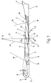
- the tongue needle shown in the drawing in the detail is punched out of steel strip and has a shaft 1 to which a needle hook 3 is connected at one end via a throat 2 and which carries in the usual way at least one needle foot (not shown in the drawing).
- a longitudinal tongue slot 5 is formed which is symmetrical to the plane of symmetry 4 and in which a needle tongue 6 is pivotally mounted.
- the needle tongue 6 is mounted on a tongue axis 7 which either consists in the form of bearing pins pressed out inwardly from the shaft cheeks 8 which delimit the tongue slot 5 on both sides or consists of a separate cylindrical bearing axis which is held at the ends in the shaft cheeks 8.
- the tongue 6 is formed with a tongue spoon 9 which, when the tongue is closed, engages over the tip of the needle hook 3, as shown in broken lines in FIG. 1.
- the tongue 6 can be pivoted between the mentioned closed position, shown in broken lines in FIG. 1, and a fully open position, shown in solid lines in FIG. 1, in which it takes up a reserve and rests on contact surfaces 11 with contact surfaces 10 on the back of the tongue spoon 9, which are arranged on the shaft 1 in the region of the upper edges 12 of the tongue slot 5.
- the recessed contact surfaces lying on both sides of the tongue slot 5 are formed in the shape of the contact surfaces 10 on the back of the spoon 9 of the tongue 6 corresponding shape impressions in the shaft 1.
- the contact surfaces 10 on the back of the tongue spoon 9 are in turn designed as wedge-shaped flanks, the normal rounding on the back of the tongue spoon possibly being sufficient for this purpose.
- the tongue slot 5 is subdivided into three parts 13, 14, 15 which, viewed from the needle hook 3, are arranged adjacent to one another in the longitudinal direction of the shaft:
- the first slot part 13 contains the tongue axis 7 and has an opening 16 to the shaft back 17 below the tongue axis 7. It is curved in a circular arc, its radius being indicated at 18 in FIG. 1.
- the width of the first slot part 13, designated by 19 in FIGS. 2, 3, is chosen with regard to the width dimensions of the tongue 6 so that the tongue 6 is guided laterally in its undamped pivoting movement about the tongue axis 7. This lateral guidance ensures that the tongue spoon 9 rests properly on the tip of the needle hook 3 in the closed position.
- the second slot part 14 is also curved in a circular arc, its radius of curvature being designated by 20 in FIG. 1.
- the center of curvature 21 lies on an imaginary line 22, which is oriented at right angles to the shaft back 17 in the region of the two contact surfaces 11, which are evidently formed in the region of this second slot part 14.
- the second slot part 14 is deeper than half the shaft height. It is then closed at the opening 16 towards the back of the shaft by a web-shaped shaft part 23, the minimum height of which is indicated at 24 and lies on line 22. This ensures that the two contact surfaces 11 are located above the lowest point of the second slot part 14.
- the width of the second slot part 14 indicated at 25 in FIGS. 2, 3 is substantially larger than the width 19 of the first slot part 13.
- the ratio of the width 19 of the first slot part 13 to the width 25 of the second slot part 14 is in the range of approximately 2 : 3 to 2: 5, preferably 2: 3.
- the length of the second slot part 14 in the longitudinal direction of the shaft is dimensioned such that the second slot part 14 protrudes beyond the end of the tongue 6 located in the reserve in the manner shown in FIG. 1, while on the other side it comes close to the tongue axis 7 is enough; it also depends on the circumstances of the respective latch needle, in particular the shaft height and the shaft thickness.
- the third slot part 15 is also curved in the shape of a circular arc, its radius of curvature being indicated at 26. As a rule, it is considerably larger (twice and more) than the radius of curvature 18 of the first slot part 13 and the radius of curvature 20 of the second slot part 14.
- the two radii of curvature 18, 20 are generally approximately the same size or the radius of curvature 20 of the second slot part 14 is larger (by 10 to 40%) than the radius of curvature 18 of the first slot part 13.
- the third slot part 15 is for the back of the shaft 17 closed and causes an extension of the web-like shaft part 23 formed by the second slot part 14, the minimum height indicated at 27 being of the order of magnitude of the minimum height 24 of the second slot part 14, so that overall in the manner shown in FIG. 1 results in a substantially flat surface area which delimits the two slot parts 14, 15 on the bottom side along the web-like shaft part 23 and its extension. It is then adjoined by a curved surface area 28 with which the third slot part 15 runs out to the upper side of the shaft.
- slot parts 14, 15 and also the slot part 13
- the slot parts 14, 15 are not exactly in the form of an arc of a circle, but rather, for example, in sections, by moving the milling cutter producing the respective slot part in the longitudinal direction of the shaft.
- the third slot part 15 is narrower than the second slot part 14. Its width is indicated at 29 in FIGS. 2, 3 and is selected in practice so that the ratio of the width 29 of the third slot part 15 to the width 25 of the second slot part 14 is in the range of about 7: 4 to 7: 6.5.
- the length of the third slit part 15 is chosen in view of the elastic deformability to be achieved in the area of the contact surfaces 11. However, the third slot part 15 always projects in the longitudinal direction beyond the wider second slot part 12.
- the tongue 6 strikes the contact surfaces 11 with the wedge-shaped contact surfaces of the back of its tongue spoon 9. Since these are arranged in the area of the particularly wide second slot part 14, ie in an area in which the cheek pieces 8 are thinner and thus more elastic, the impact of the tongue is damped properly. Because of through the larger slot width due to the greater distance between the two support surfaces 11 from each other, the tongue back can penetrate correspondingly deeper into the slot part 14, so that the exact position of the shape impressions containing the support surfaces 11 is not so important. These effects are further optimized by the fact that the contact surfaces 11, as already mentioned, lie immediately above the lowest point (at 24) of the curved - or in the case of a straight slot part above the deepest area - slot part 14.
- the above-described design of the tongue slot 5 with three differently wide slot parts or sections 13, 14, 15 is intended in particular for high-performance needles for large and small circular knitting machines, in particular for needles with a larger needle thickness, for example from 0.48 mm. However, it can also be used for latch needles with a smaller thickness.
Landscapes
- Engineering & Computer Science (AREA)
- Textile Engineering (AREA)
- Knitting Machines (AREA)
Applications Claiming Priority (2)
| Application Number | Priority Date | Filing Date | Title |
|---|---|---|---|
| DE19512375A DE19512375C1 (de) | 1995-04-01 | 1995-04-01 | Zungennadel für Maschinen zur Herstellung von Maschenware |
| DE19512375 | 1995-04-01 |
Publications (3)
| Publication Number | Publication Date |
|---|---|
| EP0735174A2 true EP0735174A2 (fr) | 1996-10-02 |
| EP0735174A3 EP0735174A3 (fr) | 1997-03-05 |
| EP0735174B1 EP0735174B1 (fr) | 2001-06-13 |
Family
ID=7758620
Family Applications (1)
| Application Number | Title | Priority Date | Filing Date |
|---|---|---|---|
| EP96103544A Expired - Lifetime EP0735174B1 (fr) | 1995-04-01 | 1996-03-07 | Aiguille à clapet pour des machines de fabrication de tricot |
Country Status (5)
| Country | Link |
|---|---|
| US (1) | US5609045A (fr) |
| EP (1) | EP0735174B1 (fr) |
| JP (1) | JP2929523B2 (fr) |
| CA (1) | CA2172770C (fr) |
| DE (2) | DE19512375C1 (fr) |
Cited By (1)
| Publication number | Priority date | Publication date | Assignee | Title |
|---|---|---|---|---|
| KR101941122B1 (ko) * | 2018-08-27 | 2019-01-22 | 이일영 | 편기용 니들 및 이를 갖는 환편기 |
Families Citing this family (4)
| Publication number | Priority date | Publication date | Assignee | Title |
|---|---|---|---|---|
| DE102004049061B4 (de) * | 2004-10-08 | 2006-08-24 | Groz-Beckert Kg | Zungennadel |
| EP1767678B1 (fr) * | 2005-09-22 | 2008-03-26 | Groz-Beckert KG | Aiguille à tricoter pour métier à tricoter |
| EP1870502B1 (fr) * | 2006-06-21 | 2009-07-29 | Groz-Beckert KG | Aiguille à clapet pour machine textile formant des mailles |
| EP3604651A1 (fr) * | 2018-08-03 | 2020-02-05 | Groz-Beckert KG | Aiguille à clapet |
Family Cites Families (7)
| Publication number | Priority date | Publication date | Assignee | Title |
|---|---|---|---|---|
| US3031867A (en) * | 1958-07-28 | 1962-05-01 | Groz & Soehne Theodor | Latch needle for knitting machines or the like |
| DE2714607C3 (de) * | 1977-04-01 | 1983-12-08 | Theodor Groz & Söhne & Ernst Beckert Nadelfabrik KG, 7470 Albstadt | Zungennadel für Maschinen zur Herstellung von Maschenware |
| JPS5415055A (en) * | 1977-07-06 | 1979-02-03 | Fukuhara Needle Co Ltd | Composite needle and its production |
| JPS6044416B2 (ja) * | 1982-10-04 | 1985-10-03 | 福原ニ−ドル株式会社 | メリヤス針 |
| DE3331030C1 (de) * | 1983-08-27 | 1984-10-04 | Theodor Groz & Söhne & Ernst Beckert Nadelfabrik KG, 7470 Albstadt | Zungennadel fuer Maschinen zur Herstellung von Maschenware |
| DE3331031C2 (de) * | 1983-08-27 | 1985-07-11 | Theodor Groz & Söhne & Ernst Beckert Nadelfabrik KG, 7470 Albstadt | Zungennadel für maschenbildende Textilmaschinen |
| DE4324232C2 (de) * | 1993-07-20 | 2002-05-29 | Sipra Patent Beteiligung | Zungennadel für Maschinen zur Herstellung von Maschenware |
-
1995
- 1995-04-01 DE DE19512375A patent/DE19512375C1/de not_active Expired - Fee Related
-
1996
- 1996-03-07 EP EP96103544A patent/EP0735174B1/fr not_active Expired - Lifetime
- 1996-03-07 DE DE59607062T patent/DE59607062D1/de not_active Expired - Lifetime
- 1996-03-27 CA CA002172770A patent/CA2172770C/fr not_active Expired - Fee Related
- 1996-03-29 US US08/623,707 patent/US5609045A/en not_active Expired - Lifetime
- 1996-04-01 JP JP8079233A patent/JP2929523B2/ja not_active Expired - Lifetime
Cited By (1)
| Publication number | Priority date | Publication date | Assignee | Title |
|---|---|---|---|---|
| KR101941122B1 (ko) * | 2018-08-27 | 2019-01-22 | 이일영 | 편기용 니들 및 이를 갖는 환편기 |
Also Published As
| Publication number | Publication date |
|---|---|
| CA2172770A1 (fr) | 1996-10-02 |
| DE19512375C1 (de) | 1996-06-20 |
| CA2172770C (fr) | 1999-04-13 |
| EP0735174A3 (fr) | 1997-03-05 |
| DE59607062D1 (de) | 2001-07-19 |
| EP0735174B1 (fr) | 2001-06-13 |
| US5609045A (en) | 1997-03-11 |
| JP2929523B2 (ja) | 1999-08-03 |
| JPH08269852A (ja) | 1996-10-15 |
Similar Documents
| Publication | Publication Date | Title |
|---|---|---|
| DE69014791T2 (de) | Schneideinsatz. | |
| DE2252349C2 (de) | Schneideinsatz für Werkzeuge der spanabhebenden Bearbeitung | |
| DE2834738C2 (de) | Nadel für Tuftingmaschinen | |
| EP1028185B1 (fr) | Aiguille de transfert pour le transfert de maille | |
| EP0735174A2 (fr) | Aguille à clapet pour des machines de fabrication de tricot | |
| EP0123914B1 (fr) | Outil de tricotage étampé pour métier à tricoter | |
| DE3133266C2 (de) | Gestanztes Strickwerkzeug für Strick- oder Wirkmaschinen | |
| DE102006004099B3 (de) | Wirkelement, insbesondere Wirknadel einer Kettenwirkmaschine, sowie Wirkmaschinen-Barre | |
| DE102006004098B3 (de) | Barre einer Wirkmaschine | |
| DE3143743C2 (de) | Schiebernadel für Kettenwirkmaschinen | |
| EP0375843B1 (fr) | Outil de tricotage étampé pour des machines textiles notamment pour des machines à tricoter | |
| DE2745793B2 (de) | Tufting-Maschine | |
| DE3331031C2 (de) | Zungennadel für maschenbildende Textilmaschinen | |
| EP0405085B1 (fr) | Outil pour des machines formant des mailles, notamment des machines à tricoter | |
| EP0426994B1 (fr) | Organe de tricotage estampé pour machines textiles | |
| DE19517602C1 (de) | Spitzennadel | |
| EP1303659B1 (fr) | Aiguille a clapet a tige de clapet abaissee | |
| DE2820958C3 (de) | Gabelnadel | |
| EP0148972B1 (fr) | Aiguille à clapet pour les machines de fabrication de tricot | |
| DE19729145C1 (de) | Gestanztes Strickwerkzeug für Textilmaschinen, insbesondere für Strick- und Wirkmaschinen | |
| DE1111328B (de) | UEbertragungsplatine fuer Rundstrick-maschinen | |
| DE4324232C2 (de) | Zungennadel für Maschinen zur Herstellung von Maschenware | |
| DE3402660A1 (de) | Platine fuer eine rundstrickmaschine | |
| EP1303658B1 (fr) | Aiguille a clapet a fente de clapet abaissee | |
| DE2818711A1 (de) | Zungennadel |
Legal Events
| Date | Code | Title | Description |
|---|---|---|---|
| PUAI | Public reference made under article 153(3) epc to a published international application that has entered the european phase |
Free format text: ORIGINAL CODE: 0009012 |
|
| AK | Designated contracting states |
Kind code of ref document: A2 Designated state(s): DE FR GB IT |
|
| PUAL | Search report despatched |
Free format text: ORIGINAL CODE: 0009013 |
|
| AK | Designated contracting states |
Kind code of ref document: A3 Designated state(s): DE FR GB IT |
|
| RAP1 | Party data changed (applicant data changed or rights of an application transferred) |
Owner name: GROZ-BECKERT KOMMANDITGESELLSCHAFT |
|
| 17P | Request for examination filed |
Effective date: 19970805 |
|
| GRAG | Despatch of communication of intention to grant |
Free format text: ORIGINAL CODE: EPIDOS AGRA |
|
| 17Q | First examination report despatched |
Effective date: 20000523 |
|
| GRAG | Despatch of communication of intention to grant |
Free format text: ORIGINAL CODE: EPIDOS AGRA |
|
| GRAH | Despatch of communication of intention to grant a patent |
Free format text: ORIGINAL CODE: EPIDOS IGRA |
|
| GRAH | Despatch of communication of intention to grant a patent |
Free format text: ORIGINAL CODE: EPIDOS IGRA |
|
| GRAA | (expected) grant |
Free format text: ORIGINAL CODE: 0009210 |
|
| AK | Designated contracting states |
Kind code of ref document: B1 Designated state(s): DE FR GB IT |
|
| GBT | Gb: translation of ep patent filed (gb section 77(6)(a)/1977) |
Effective date: 20010613 |
|
| REF | Corresponds to: |
Ref document number: 59607062 Country of ref document: DE Date of ref document: 20010719 |
|
| ET | Fr: translation filed | ||
| ITF | It: translation for a ep patent filed | ||
| REG | Reference to a national code |
Ref country code: GB Ref legal event code: IF02 |
|
| PLBE | No opposition filed within time limit |
Free format text: ORIGINAL CODE: 0009261 |
|
| STAA | Information on the status of an ep patent application or granted ep patent |
Free format text: STATUS: NO OPPOSITION FILED WITHIN TIME LIMIT |
|
| 26N | No opposition filed | ||
| PGFP | Annual fee paid to national office [announced via postgrant information from national office to epo] |
Ref country code: FR Payment date: 20120403 Year of fee payment: 17 |
|
| PGFP | Annual fee paid to national office [announced via postgrant information from national office to epo] |
Ref country code: GB Payment date: 20120322 Year of fee payment: 17 |
|
| PGFP | Annual fee paid to national office [announced via postgrant information from national office to epo] |
Ref country code: IT Payment date: 20120329 Year of fee payment: 17 |
|
| GBPC | Gb: european patent ceased through non-payment of renewal fee |
Effective date: 20130307 |
|
| REG | Reference to a national code |
Ref country code: FR Ref legal event code: ST Effective date: 20131129 |
|
| PG25 | Lapsed in a contracting state [announced via postgrant information from national office to epo] |
Ref country code: FR Free format text: LAPSE BECAUSE OF NON-PAYMENT OF DUE FEES Effective date: 20130402 Ref country code: GB Free format text: LAPSE BECAUSE OF NON-PAYMENT OF DUE FEES Effective date: 20130307 |
|
| PG25 | Lapsed in a contracting state [announced via postgrant information from national office to epo] |
Ref country code: IT Free format text: LAPSE BECAUSE OF NON-PAYMENT OF DUE FEES Effective date: 20130307 |
|
| PGFP | Annual fee paid to national office [announced via postgrant information from national office to epo] |
Ref country code: DE Payment date: 20150119 Year of fee payment: 20 |
|
| REG | Reference to a national code |
Ref country code: DE Ref legal event code: R071 Ref document number: 59607062 Country of ref document: DE |