EP0735182A2 - Section de presse - Google Patents
Section de presse Download PDFInfo
- Publication number
- EP0735182A2 EP0735182A2 EP96102391A EP96102391A EP0735182A2 EP 0735182 A2 EP0735182 A2 EP 0735182A2 EP 96102391 A EP96102391 A EP 96102391A EP 96102391 A EP96102391 A EP 96102391A EP 0735182 A2 EP0735182 A2 EP 0735182A2
- Authority
- EP
- European Patent Office
- Prior art keywords
- belt
- press
- suction
- suctionable
- take
- Prior art date
- Legal status (The legal status is an assumption and is not a legal conclusion. Google has not performed a legal analysis and makes no representation as to the accuracy of the status listed.)
- Granted
Links
Images

Classifications
-
- D—TEXTILES; PAPER
- D21—PAPER-MAKING; PRODUCTION OF CELLULOSE
- D21F—PAPER-MAKING MACHINES; METHODS OF PRODUCING PAPER THEREON
- D21F3/00—Press section of machines for making continuous webs of paper
- D21F3/02—Wet presses
- D21F3/04—Arrangements thereof
- D21F3/045—Arrangements thereof including at least one extended press nip
-
- D—TEXTILES; PAPER
- D21—PAPER-MAKING; PRODUCTION OF CELLULOSE
- D21F—PAPER-MAKING MACHINES; METHODS OF PRODUCING PAPER THEREON
- D21F3/00—Press section of machines for making continuous webs of paper
- D21F3/02—Wet presses
- D21F3/04—Arrangements thereof
-
- D—TEXTILES; PAPER
- D21—PAPER-MAKING; PRODUCTION OF CELLULOSE
- D21G—CALENDERS; ACCESSORIES FOR PAPER-MAKING MACHINES
- D21G9/00—Other accessories for paper-making machines
- D21G9/0063—Devices for threading a web tail through a paper-making machine
Definitions
- the invention relates to a press section for a machine for producing a fibrous web, in particular paper or cardboard web, in particular with the features specified in the preamble of claim 1.
- Such a press section which has a double felted press unit, is known from EP 0 598 991 A1.
- the transfer area between the press unit (which can be the only press unit or one of several press units) and the downstream unit has problems.
- the transfer area should be designed in such a way that the paper web in the press unit is optimally dewatered. This is of course the most important function of a press section.
- the transfer strip (or the full width of the paper web) should be transferred easily and reliably from the press unit to the downstream unit. To date, these two requirements have not been satisfactorily met at the same time. With a double-felted press unit, the paper web runs together with the upper felt and the lower felt through the press nip of the press unit.
- the paper web is sandwiched between these two felts.
- the two felt belts absorb water from the paper web in the press nip. When exiting the press nip, the press pressure naturally stops. At this point there is a risk that water will flow back from the two felt belts back to the paper web so that it is rewet. To avoid this, the two felt belts should be separated from the paper web as soon as possible after passing through the press nip.
- one of the two felt belts is guided after leaving the press nip in such a way that an angle of divergence between the paper web and the felt belt is created.
- This transfer belt is now supposed to transfer the paper web to a so-called “take-off belt”; this is a felt belt or wire belt of the downstream unit.
- the take-off belt runs over a take-off device which, in the subject of EP 0 598 991, is designed as a take-off suction roll. This is to ensure that the paper web behind the transfer point follows the take-off belt.
- a frequent uncertainty factor when changing the paper web from the transfer belt to the take-off belt is the quality and the condition of the endless belts, which changes over time, especially when it comes to felts.
- felts the structure of which is selected so that they are primarily suitable for transporting the web. It often happens that the web has to hang on the underside of the felt, supported by adhesive forces of the still relatively wet web on the moistened outside of the felt. In this case, this is designed such that it contains a relatively large amount of water in its pores.
- Such felts are constructed in such a way that they can absorb a lot of water from the paper web and store it inside (ie in a middle layer). The water moves quickly through the outside of the felt, so that the outside remains relatively dry. As a result, the web adheres less well to the outside of the felt; thus there is a risk that the web - especially if it hangs on the underside of the felt - will come loose from the felt. In this case, the operation of the paper machine is temporarily disrupted; that is, the paper web is torn off and the paper web must be re-threaded into the paper machine. If necessary, the felt must also be replaced prematurely. Such interruptions in operation mean, however, that the so-called run efficiency of the paper machine drops to an unsatisfactory value.
- the invention is therefore based on the object of designing a press section which has the features of the preamble of claim 1 in such a way that not only is the dewatering capacity of the press unit as high as possible, but in particular that high running efficiency is ensured.
- the transfer of the paper web from the press unit to the downstream unit should take place as largely as possible without interference.
- the machine operator - by pivoting the above-mentioned movable deflection roller - can ensure that the transfer belt is guided in such a way that it remains in contact with the removal belt behind the non-suctionable guide element up to a suction element.
- interruptions in operation caused by the occasional falling of the paper web from one of the belts can be completely (or almost completely) avoided.
- a certain amount of rewetting of the web under the action of the suction element must, however, be accepted.
- Mode of operation I will preferably be selected if the transfer belt is essentially designed as a drainage belt, so that the side coming into contact with the paper web contains little moisture even behind the press nip. As a result, the paper web will generally change to the take-off belt without any problems (and without the aid of a suction element). Such a design of the transfer belt also acts in the direction of an additional increase in the dewatering performance of the press unit.
- mode II i.e. guiding the transfer belt and take-off belt to the suction element together
- mode II is only used temporarily during the start-up of the paper machine or after a possible web break, i.e. always when the paper web has to be "re-threaded” into the paper machine. Reliable transfer of the beginning of the paper web to the take-off belt is ensured by means of the suction element. Then, by swiveling the movable deflecting roller, the mode I is switched to in order to use the possibilities for increasing the drainage capacity.
- the transfer belt has the primary function of a conveyor belt, ie it only serves as a second line as a drainage belt. This is the case, for example, when the transfer belt first has to remove the paper web from the wire section and then pass it through the press unit.
- mode II from the outset, namely in order to achieve the highest possible running efficiency of the paper machine.
- a third mode of operation can also be used, in which the movable deflecting roller is adjusted into such a position that the transfer belt is permanently out of contact with the take-off belt. In this case, the paper web must run over a free paper draw from the transfer belt to the take-off belt during normal continuous operation.
- the paper machine operator has more freedom than before when selecting the felts or screens for the press section thanks to the invention. He can also select the cheapest from several possible operating modes.
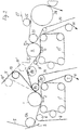
- FIG. 1 shows a press section according to the invention, or a part thereof, in a schematic side view.
- FIG. 1 shows a press unit, formed by a normal press roll 1 and by a shoe press roll with press shoe 2 and press belt 3. Both rolls together form a press nip through which an invisible paper web runs together with two felt belts 4 and 5.
- the upper felt belt 4 transports the paper web from a wire section into the press section in a known manner; the paper web comes into contact with the lower felt belt 5 in the area of a guide roller 6. Immediately at the exit from the press nip, the upper felt belt 4 separates from the paper web and runs back to the wire section via a guide roller 7 and further guide rollers which are not visible.
- the paper web runs together with the lower felt belt or "transfer belt” 5 to a transfer point which is arranged as close as possible to the exit from the press nip.
- the transfer point is formed by a take-off roller 8a, on which a take-off belt 14 comes into contact with the paper web.
- the paper web runs from the take-off roller 8a together with the take-off belt 14 to a suction roller 8b and from there into a downstream second press unit 11-13 (or into another downstream unit).
- the transfer belt 5 detaches itself directly from the paper web at the take-off roller 8a. This ensures that rewetting of the paper web from the transfer belt can only take place over a very short distance. The previously undesired additional rewetting of the paper web due to the negative pressure prevailing on the previous suction suction roll is completely avoided.
- the suction roller 8b according to the invention ensures that the paper web adheres securely to the take-off belt 14.
- the pivotable deflecting roller 10 is in such a position (10 ') that the transfer belt 5 remains in contact with the paper web up to the suction roller 8b .
- This mode of operation ensures reliable transfer of the beginning of the web to the take-off belt 14 by means of the suction roller 8b.
- This mode of operation can also be used temporarily or continuously if the transfer belt 5 reluctantly delivers the paper web to the take-off belt 14 after a long period of operation, or if the transfer belt before the press unit 1-3 has the function of a take-off belt, such as 2.
- FIG. 1 a further position 10 ′′ of the deflecting roller 10 is shown with dash-dotted lines, in which the two belts 5 and 14 remain without contact.
- This position is advantageous e.g. when the press section is idling, or when one of the two press units is at a standstill or at a different working speed than the other press unit.
- this position can also be used in special cases during normal continuous operation, e.g. in the production of wet-strength paper webs.
- the invention is implemented in the same way in the second press unit 11-20 or FIG. 1.
- the transfer belt 5 is not the lower but the upper felt belt of the first press unit 1, 2, 3. Before this press unit, the transfer belt 5 serves as a take-off belt; because it removes the paper web from the wire section in a known manner by means of a take-off suction roll 5A; only a small piece of the sieve belt S is shown.
- the paper web hangs on the underside of the transfer belt 5; the same applies when the paper web runs out together with the transfer belt from the press unit 1-3.
- the risk that the paper web will detach from the transfer belt 5 is very low; because the web running distance from the outlet from the press nip to the take-off point on the roller 8a is kept very short according to the invention.
- FIG. 1 shoe press rolls are provided, each with a tubular press belt 3 (which is closed on the two end faces), the arrangement according to FIG. 2 has press belts 3 'and 13', which rotate over several guide rolls. But it is also possible in Fig. 2 a Schuzpreßwalzen arrangement corresponding to FIG. 1.
- the paper web runs behind the second press unit 11, 12, 13 'in a short free paper draw from the press roll 11 to a transfer screen or transfer felt 24, which runs, among other things, over a guide roll 25 and over a first drying cylinder 28.
- the paper web is transferred to a dryer fabric 27, which runs over a guide roller 26 to the drying cylinder 28 and then guides the paper web in a known manner over the other drying cylinders, not shown.
- the guide roller 25 can be replaced by a roller arrangement similar to 8a / 8b / 10 (10 '/ 10' ').
- the drying cylinder 28 can be replaced by a normal guide roller.
- the transfer point of the web to the dryer fabric 27 can also be arranged behind the cylinder 28 or behind the normal guide roller.
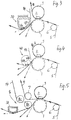
- FIG. 3 shows a modification to FIG. 1 and FIG. 2.
- a stationary guide suction shoe 30 is provided in FIG. 3 with a convexly curved guide surface for the Removal belt 14.
- This guide surface comprises a non-suctionable part 30a, which is arranged as close as possible to the pressing unit 1-3, and a suction zone 30b adjoining it.
- a guide suction roller 40 is provided, which instead of the non-suctionable guide element mentioned in claim 1 has a non-suctionable zone 40a and then a relatively small suction zone 40b.
- FIG. 5 as in FIG. 1 or FIG. 2, a guide roller 8a that cannot be vacuumed is provided and instead of the suction roller 8b of FIG. 1 or FIG. 2, a stationary suction shoe 38 is shown. Another possibility, namely that, is not shown 2 or 2 to be replaced by a stationary shoe and to maintain the suction guide roller 8b.
Landscapes
- Paper (AREA)
Applications Claiming Priority (2)
| Application Number | Priority Date | Filing Date | Title |
|---|---|---|---|
| DE19511988A DE19511988C1 (de) | 1995-03-31 | 1995-03-31 | Pressenpartie für eine Papiermaschine |
| DE19511988 | 1995-03-31 |
Publications (3)
| Publication Number | Publication Date |
|---|---|
| EP0735182A2 true EP0735182A2 (fr) | 1996-10-02 |
| EP0735182A3 EP0735182A3 (fr) | 1998-01-21 |
| EP0735182B1 EP0735182B1 (fr) | 2001-05-09 |
Family
ID=7758355
Family Applications (1)
| Application Number | Title | Priority Date | Filing Date |
|---|---|---|---|
| EP96102391A Expired - Lifetime EP0735182B1 (fr) | 1995-03-31 | 1996-03-01 | Section de presse |
Country Status (2)
| Country | Link |
|---|---|
| EP (1) | EP0735182B1 (fr) |
| DE (2) | DE19511988C1 (fr) |
Families Citing this family (9)
| Publication number | Priority date | Publication date | Assignee | Title |
|---|---|---|---|---|
| DE19815994A1 (de) * | 1998-04-09 | 1999-10-14 | Voith Sulzer Papiertech Patent | Übergabe einer Faserstoffbahn |
| US6261415B1 (en) | 1998-08-28 | 2001-07-17 | Valmet Karlstad Ab | Paper machine |
| WO2000071813A1 (fr) * | 1999-05-21 | 2000-11-30 | Valmet-Karlstad Ab | Section de presse dotée d'un dispositif stabilisateur de bande |
| WO2000071812A1 (fr) * | 1999-05-21 | 2000-11-30 | Valmet-Karlstad Ab | Section de presse dotée d'un dispositif stabilisateur de bande |
| DE10015357A1 (de) * | 2000-03-28 | 2001-10-04 | Voith Paper Patent Gmbh | Bahnabnahmeanordnung |
| DE50009627D1 (de) * | 1999-11-16 | 2005-04-07 | Voith Paper Patent Gmbh | Verfahren zum Überführen einer zu behandelnden Faserstoffbahn |
| DE10022605A1 (de) * | 2000-05-09 | 2001-11-15 | Voith Paper Patent Gmbh | Pressenpartie |
| DE10116364A1 (de) * | 2001-04-02 | 2002-10-10 | Voith Paper Patent Gmbh | Saugelement |
| DE102016201333A1 (de) * | 2016-01-29 | 2017-08-03 | Voith Patent Gmbh | Pressenpartie |
Family Cites Families (2)
| Publication number | Priority date | Publication date | Assignee | Title |
|---|---|---|---|---|
| DE4026021C2 (de) * | 1990-08-17 | 1995-10-12 | Voith Gmbh J M | Pressenpartie einer Papiermaschine |
| ATE133217T1 (de) * | 1992-11-24 | 1996-02-15 | Voith Gmbh J M | Pressenpartie für eine papiermaschine |
-
1995
- 1995-03-31 DE DE19511988A patent/DE19511988C1/de not_active Expired - Fee Related
-
1996
- 1996-03-01 EP EP96102391A patent/EP0735182B1/fr not_active Expired - Lifetime
- 1996-03-01 DE DE59606858T patent/DE59606858D1/de not_active Expired - Fee Related
Also Published As
| Publication number | Publication date |
|---|---|
| EP0735182A3 (fr) | 1998-01-21 |
| EP0735182B1 (fr) | 2001-05-09 |
| DE59606858D1 (de) | 2001-06-13 |
| DE19511988C1 (de) | 1996-08-01 |
Similar Documents
| Publication | Publication Date | Title |
|---|---|---|
| DE3328162C2 (de) | Papiermaschine | |
| DE69620788T2 (de) | Verfahren und vorrichtung zur entwässerung einer papier- oder pappebahn durch pressen | |
| DE4224730C1 (en) | Tissue paper mfg. machine preventing moisture return - comprises shoe press for press unit(s) for drying tissue web, for min. press units | |
| DE4218595C2 (de) | Maschine zur Herstellung einer Papierbahn | |
| DE4112355A1 (de) | Pressenpartie einer papiermaschine | |
| DE69208460T2 (de) | Vorrichtung zur herstellung einer getrockneten papierbahn | |
| DE69930386T2 (de) | Formierpressenpartie in einer papiermaschine und verfahren zur überführung der bahn von dem former zu der pressenpartie | |
| EP0598991B1 (fr) | Section de presse pour une machine à papier | |
| DE2920713A1 (de) | Verfahren und vorrichtung zur abnahme einer bahn vom bildungssieb und zu ihrer ueberfuehrung an ein tuch der presspartie einer papiermaschine | |
| DE19511988C1 (de) | Pressenpartie für eine Papiermaschine | |
| EP3987113B1 (fr) | Machine destinée à la fabrication d'une bande de matière fibreuse | |
| DE19855215A1 (de) | Verfahren zum Entfernen von Wasser aus einer Papier- oder Kartonbahn mittels Preßung, und Papier- oder Kartonmaschine | |
| DE102008043294A1 (de) | Verfahren und Vorrichtung zum Überführen der Papierbahn von einem Stützgewebe | |
| EP0608534B1 (fr) | Presse humide pour une machine à papier | |
| WO1991012370A1 (fr) | Dispositif de transfert d'une bande de la zone de pressage vers la zone de sechage d'une machine a papier | |
| DE4201107C2 (de) | Trockenpartie | |
| DE2000661C3 (de) | Bahnbildungszone einer Papiermaschine | |
| DE19602697B4 (de) | Trockenpartie | |
| EP0803604B1 (fr) | Presse humide | |
| EP1478806B1 (fr) | Dispositif de lissage | |
| WO1995020068A1 (fr) | Transport sans traction d'une bande dans une section de compression | |
| DE4335024C2 (de) | Pressenpartie einer Papiermaschine und Überführeinrichtung | |
| DE1761505A1 (de) | Papiermaschine | |
| DE9101248U1 (de) | Trockenpartie für Papiermaschinen | |
| DE10132652A1 (de) | Pressenanordnung |
Legal Events
| Date | Code | Title | Description |
|---|---|---|---|
| PUAI | Public reference made under article 153(3) epc to a published international application that has entered the european phase |
Free format text: ORIGINAL CODE: 0009012 |
|
| 17P | Request for examination filed |
Effective date: 19960228 |
|
| AK | Designated contracting states |
Kind code of ref document: A2 Designated state(s): DE FI FR IT SE |
|
| PUAL | Search report despatched |
Free format text: ORIGINAL CODE: 0009013 |
|
| AK | Designated contracting states |
Kind code of ref document: A3 Designated state(s): DE FI FR IT SE |
|
| RAP1 | Party data changed (applicant data changed or rights of an application transferred) |
Owner name: VOITH SULZER PAPIERTECHNIK PATENT GMBH |
|
| GRAG | Despatch of communication of intention to grant |
Free format text: ORIGINAL CODE: EPIDOS AGRA |
|
| 17Q | First examination report despatched |
Effective date: 20000816 |
|
| GRAG | Despatch of communication of intention to grant |
Free format text: ORIGINAL CODE: EPIDOS AGRA |
|
| GRAH | Despatch of communication of intention to grant a patent |
Free format text: ORIGINAL CODE: EPIDOS IGRA |
|
| GRAH | Despatch of communication of intention to grant a patent |
Free format text: ORIGINAL CODE: EPIDOS IGRA |
|
| RAP1 | Party data changed (applicant data changed or rights of an application transferred) |
Owner name: VOITH PAPER PATENT GMBH |
|
| GRAA | (expected) grant |
Free format text: ORIGINAL CODE: 0009210 |
|
| AK | Designated contracting states |
Kind code of ref document: B1 Designated state(s): DE FI FR IT SE |
|
| PG25 | Lapsed in a contracting state [announced via postgrant information from national office to epo] |
Ref country code: IT Free format text: LAPSE BECAUSE OF FAILURE TO SUBMIT A TRANSLATION OF THE DESCRIPTION OR TO PAY THE FEE WITHIN THE PRE;WARNING: LAPSES OF ITALIAN PATENTS WITH EFFECTIVE DATE BEFORE 2007 MAY HAVE OCCURRED AT ANY TIME BEFORE 2007. THE CORRECT EFFECTIVE DATE MAY BE DIFFERENT FROM THE ONE RECORDED.SCRIBED TIME-LIMIT Effective date: 20010509 Ref country code: FR Free format text: LAPSE BECAUSE OF FAILURE TO SUBMIT A TRANSLATION OF THE DESCRIPTION OR TO PAY THE FEE WITHIN THE PRESCRIBED TIME-LIMIT Effective date: 20010509 Ref country code: FI Free format text: LAPSE BECAUSE OF FAILURE TO SUBMIT A TRANSLATION OF THE DESCRIPTION OR TO PAY THE FEE WITHIN THE PRESCRIBED TIME-LIMIT Effective date: 20010509 |
|
| REF | Corresponds to: |
Ref document number: 59606858 Country of ref document: DE Date of ref document: 20010613 |
|
| EN | Fr: translation not filed | ||
| PG25 | Lapsed in a contracting state [announced via postgrant information from national office to epo] |
Ref country code: SE Free format text: LAPSE BECAUSE OF NON-PAYMENT OF DUE FEES Effective date: 20020302 |
|
| PLBE | No opposition filed within time limit |
Free format text: ORIGINAL CODE: 0009261 |
|
| STAA | Information on the status of an ep patent application or granted ep patent |
Free format text: STATUS: NO OPPOSITION FILED WITHIN TIME LIMIT |
|
| 26N | No opposition filed | ||
| PG25 | Lapsed in a contracting state [announced via postgrant information from national office to epo] |
Ref country code: DE Free format text: LAPSE BECAUSE OF NON-PAYMENT OF DUE FEES Effective date: 20021001 |
|
| EUG | Se: european patent has lapsed |
Ref document number: 96102391.8 |