EP0735193B1 - Dispositif de fraisage pour enlever des revêtements routiers - Google Patents
Dispositif de fraisage pour enlever des revêtements routiers Download PDFInfo
- Publication number
- EP0735193B1 EP0735193B1 EP96105033A EP96105033A EP0735193B1 EP 0735193 B1 EP0735193 B1 EP 0735193B1 EP 96105033 A EP96105033 A EP 96105033A EP 96105033 A EP96105033 A EP 96105033A EP 0735193 B1 EP0735193 B1 EP 0735193B1
- Authority
- EP
- European Patent Office
- Prior art keywords
- road
- conveyor belt
- machine
- frame
- scarifying machine
- Prior art date
- Legal status (The legal status is an assumption and is not a legal conclusion. Google has not performed a legal analysis and makes no representation as to the accuracy of the status listed.)
- Expired - Lifetime
Links
Images
Classifications
-
- E—FIXED CONSTRUCTIONS
- E01—CONSTRUCTION OF ROADS, RAILWAYS, OR BRIDGES
- E01C—CONSTRUCTION OF, OR SURFACES FOR, ROADS, SPORTS GROUNDS, OR THE LIKE; MACHINES OR AUXILIARY TOOLS FOR CONSTRUCTION OR REPAIR
- E01C23/00—Auxiliary devices or arrangements for constructing, repairing, reconditioning, or taking-up road or like surfaces
- E01C23/06—Devices or arrangements for working the finished surface; Devices for repairing or reconditioning the surface of damaged paving; Recycling in place or on the road
- E01C23/08—Devices or arrangements for working the finished surface; Devices for repairing or reconditioning the surface of damaged paving; Recycling in place or on the road for roughening or patterning; for removing the surface down to a predetermined depth high spots or material bonded to the surface, e.g. markings; for maintaining earth roads, clay courts or like surfaces by means of surface working tools, e.g. scarifiers, levelling blades
- E01C23/085—Devices or arrangements for working the finished surface; Devices for repairing or reconditioning the surface of damaged paving; Recycling in place or on the road for roughening or patterning; for removing the surface down to a predetermined depth high spots or material bonded to the surface, e.g. markings; for maintaining earth roads, clay courts or like surfaces by means of surface working tools, e.g. scarifiers, levelling blades using power-driven tools, e.g. vibratory tools
- E01C23/088—Rotary tools, e.g. milling drums
Definitions
- the invention concerns a road scarifying machine used for the removal of road surfacings, equipped with an auger for the lateral discharge of the debris resulting from the crushing of the road surfacing.
- road scarifers are machines used for the removal of the asphalt surfacing which covers the roadways. They essentially comprise a wheel-mounted frame, provided with a driving unit, with a driver's seat and with a milling drum which comes into contact with the road surfacing to be removed.
- the milling drum is driven into rotation and, by means of the peripheral projections with which it is provided, it crushes the road surfacing with which it is in contact and into which it penetrates.
- the debris of said crushing is a material which can still be used for subsequent use and, therefore, it is removed from the working area of the milling drum before any subsequent digging is done.
- the road scarifying machines are equipped with the milling drum only, but they do not present any suitable means to permit to move the crushed material away from the working area.
- the described road scarifying machines complete with a conveyor belt are realized according two different embodiments.
- This embodiment is preferred for the road scarifying machines which present milling drums having a limited width and, therefore, suited to perform localized removals, such as diggings for the laying of pipelines or electrical cables.
- DE-A-2 505 561 discloses a rod scarifying machine with a milling drum and conveyance means of the crushing of the surface road transversally disposed in relation to the frame of said machine.
- a conveyor belt is provided substantially perpendicular to the conveyance means.
- DE-A-3 101 216 discloses a road cutting machine with a cutter fitted with a conveyor belt unit for returning stripped material to a container belonging to the machine.
- a first problem is that the presence of such a conveyor belt, whether it is positioned in front of or behind the road scarifying machine, increases the overall dimensions of the machine, thus making it more difficult to drive it and, therefore, reducing its control.
- the present invention proposes to overcome all the mentioned limitations and inconveniences.
- one of the purposes of the invention is to realize a road scarifying machine which permits to clear immediately the area of the roadway where the milling drum is operating from the debris resulting from the crushing of the road surfacing itself.
- Another purpose of the machine according to the invention is to give the driver a better view of the surronding working area, as compared with the road scarifying machines belonging to the known technique complete with a conveyor belt and equivalent to it.
- the road scarifying machine should it be provided with a conveyor belt, to make it possible for the driver to check the position of the conveyor belt in relation to the loading part of the lorry where the removed road surfacing is loaded, without him having to turn and, therefore, to divert his attention from driving the vehicle.
- a conveyor belt can be arranged along one of the sides of the road scarifying machine, which receives the material coming out from the auger and conveys it to a means of transportation.
- the conveyor belt is hinged on the frame of the road scarifying machine and can be made to project laterally.
- the presence of the auger conveys on the side of the machine the debris resulting from the crushing of the road surfacing, thus clearing immediately the working area of the milling drum where it is possible to start immediately the digging or the asphalt covering operations.
- the recovery of the crushed road surfacing, which can be re-used, is done afterwards through its collection with spades, power shovels, buckets and similar.
- the debris resulting from the crushing can be immediately transferred from the working area to a collecting area to be re-used afterwards.
- the presence of such a lateral conveyor belt reduces the overall dimensions of the machine and permits a better handling during its operation.
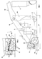
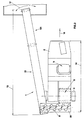
- the road scarifying machine As can be observed in the Figs. 1 and 2, the road scarifying machine according to the invention, indicated as a whole with 1, comprises a frame 2 mounted on wheels 3 which supports a driving unit 4 and a driver's seat, indicated as a whole with 5. Under frame 2 and behind the driver's seat 5, there is a milling drum 6 which is connected to frame 2 and which is put into contact with the road surfacing to be removed 7 into which it penetrates by a depth 8 which essentially corresponds to the thickness of the asphalt to be removed.
- Said milling drum 6, as can be observed in particular in Fig. 3, is provided with a plurality of milling elements 61 and is driven into rotation by a shaft 62 mechanically connected to said driving unit 4 through mechanical means 4, not represented in the drawings.
- the milling elements 61 crush the road surfacing 7 and discharge the debris, following direction 64, into a collecting channel 91 within which there are conveyance means consisting of an auger 9.
- Said auger 9 as can be observed in Fig. 3, is arranged transversally to frame 2 of the road scarifying machine and it transfers said debris 71 produced by the crushing of the road surfacing 7, to the side of the working area 72. In said area 72, thus clear from the debris of the crushing, the next digging or asphalt covering operations can then start immediately.
- the crushed material is piled on the carriageway, beside the operating area of the milling drum and is picked up afterwards in order to be used again, after undergoing a suitable treatment.
- the auger transfers directly said debris 71 on to the lateral conveyor belt 10, which is arranged with a bottom-to-top inclination, in order to convey it into the loading part of lorry 11 proceeding ahead of the machine.
- the auger is slanted from bottom-to-top according to the direction of the material discharge, so as to permit the material itself to be loaded on the conveyor belt 10.
- the advantage yielded is that, besides clearing the operating area 72 from the debris 71 of the crushing, the latter is also immediately moved away and piled up in a collecting area for a subsequent re-use.
- said conveyor belt 10 is hinged on frame 2 of the road scarifying machine by means of pivoting means, not represented in the drawings but belonging to the known technique, and is connected to driving means, also not represented in the drawings but belonging to the known technique, by means of which it can be made to project in an essentially horizontal plane, following any of the directions pointed by arrow 12.
- the lateral arrangement of the conveyor belt 10 gives the driver a better visibility as compared with equivalent road scarifying machines in which the conveyor belt is arranged in front. This is true during the progress of the road scarifying machine but especially during the working phase.
- the loading part of lorry 11 proceeding ahead of the road scarifying machine can be offset in relation to the loading direction 15 of the road scarifying machine itself.
- the road scarifying machine according to the invention permits the driver to operate without having to turn constantly to check the position of the belt in relation to the loading part of the lorry which receives the debris resulting from the crushing.
- Fig. 1 it is also interesting to observe that the front part 101 of the conveyor belt 10 can be arranged according to the configuration represented with a dotted line. This fact allows a better control of the machine during its progress and smaller overall dimensions for parking, as compared with machines equivalent to it and presenting a front or a rear conveyor belt.
- the lateral arrangement of the belt does not require the balancing ballast and, therefore, permits to reduce the costs and the vertical overall dimensions of the machine, as compared with equivalent machines of the known type.
- the conveyor belt can be applied either on the right-hand side or on the left-hand side of the road scarifying machine or, eventually, on both of them. In this last case, it will be necessary to install two augers which discharge in directions opposite to one another.
- the transversal auger can have its discharging side either on the right or on the left, or alternatively, the augers can be two in number and discharge on sides opposite to one another.
- the presence of the auger permits to immediately clear the working area from the debris resulting from the crushing at the same time as it is produced, thus making it possible to continue immediately the digging or asphalt covering operations in the working area. Moreover, the pile-up of the crushed material on the sides of the working area, permits, as has already been said, its subsequent recovery and re-use.
- the material collected by the auger is conveyed to the conveyor belt which sends it into a means of transportation.
- the machine according to the invention can be obtained in any dimensions and shapes and it can be equipped with milling drums having any diameter and any width, suited to work on road surfacings of any extent.
Landscapes
- Engineering & Computer Science (AREA)
- Mechanical Engineering (AREA)
- Mining & Mineral Resources (AREA)
- Architecture (AREA)
- Civil Engineering (AREA)
- Structural Engineering (AREA)
- Road Repair (AREA)
- Finish Polishing, Edge Sharpening, And Grinding By Specific Grinding Devices (AREA)
Claims (4)
- Un scarificateur (1) pour l'enlèvement de surfaces routières, comprenant:caractérisé en ce que lesdits moyens de transport (9) sont formés d'au moins une vis transporteuse de rotation (9) positionnée de manière adjancente par rapport au tambour de fraisage (6) et logée à l'intérieur d'un canal de récolte (91) relié audit châssis (2) dudit scarificateur (1), ledit canal de récolte (91) étant indiqué pour recevoir lesdits décombres (71) enlevés par ledit tambour de fraisage (6), ladite vis transporteuse (9) étant inclinée du fond au sommet selon la direction d'avance des décombres (71) lelong de la même vis transporteuse (9).un châssis (2) monté sur roues (3) qui soutient au moins une unité d'actionnement (4) et au moins un siège pour le pilote (5);un tambour de fraisage (6) relié audit châssis (2) et relié mécaniquement à des moyens d'alimentation indiqués pour le faire pivoter afin de briser ladite surface routière (7) avec laquelle il entre en contact,des moyens de transport (9) étant positionnés de manière transversale par rapport audit châssis (2), indiqués pour décharger sur le côté du scarifacteur (1) et hors de la zone de travail (72) du tambour de fraisage (6) les décombres (71) résultant de l'écrasement de la surface routière (7), qui sont chargés à l'intérieur de ceux-ci au moyen d'une force centrifugeuse grâce à la rotation du tambour de fraisage (6),
- Un scarificateur (1) selon la revendication 1, caractérisé en ce qu'il est muni d'une bande transporteuse (10) positionnée latéralement par rapport audit châssis (2) dudit scarificateur, ladite bande transporteuse (10) étant positionnée au niveau de la partie finale desdits moyens de transport (9) et au-dessous de ceux-ci, et indiquée pour recevoir les décombres (71) transportés par lesdits moyens de transport (9).
- Un scarificateur (1) selon la revendication 2, caractérisé en ce que ladite bande transporteuse (10) est reliée à un des côtés dudit châssis (2) à travers des moyens de rotation, lesdits moyens de rotation étant indiqués pour permettre la projection de ladite bande transporteuse (10) sur un plan essentiellement horizontal.
- Un scarificateur (1) selon la revendication 2 ou 3, caractérisé en ce que ladite bande transporteuse (10) présente sa partie finale (101) qui peut être pliée, la longueur (17) de ladite bande transporteuse pliée étant essentiellement égale à la longueur (14) dudit scarificateur (1).
Applications Claiming Priority (2)
| Application Number | Priority Date | Filing Date | Title |
|---|---|---|---|
| IT95VI000052A IT1280299B1 (it) | 1995-03-30 | 1995-03-30 | Macchina scarificatrice perfezionata per la rimozione di manti stradali |
| ITVI950052 | 1995-03-30 |
Publications (3)
| Publication Number | Publication Date |
|---|---|
| EP0735193A2 EP0735193A2 (fr) | 1996-10-02 |
| EP0735193A3 EP0735193A3 (fr) | 1996-12-18 |
| EP0735193B1 true EP0735193B1 (fr) | 1999-12-01 |
Family
ID=11425732
Family Applications (1)
| Application Number | Title | Priority Date | Filing Date |
|---|---|---|---|
| EP96105033A Expired - Lifetime EP0735193B1 (fr) | 1995-03-30 | 1996-03-29 | Dispositif de fraisage pour enlever des revêtements routiers |
Country Status (5)
| Country | Link |
|---|---|
| EP (1) | EP0735193B1 (fr) |
| AT (1) | ATE187218T1 (fr) |
| DE (1) | DE69605346T2 (fr) |
| ES (1) | ES2140741T3 (fr) |
| IT (1) | IT1280299B1 (fr) |
Cited By (1)
| Publication number | Priority date | Publication date | Assignee | Title |
|---|---|---|---|---|
| US11613855B1 (en) | 2021-10-11 | 2023-03-28 | Caterpillar Paving Products Inc. | System and method of material evacuation in mill chamber |
Families Citing this family (5)
| Publication number | Priority date | Publication date | Assignee | Title |
|---|---|---|---|---|
| IT248863Y1 (it) * | 1999-07-23 | 2003-02-20 | Bitelli Spa | Camera di contenimento per tamburo fresante di macchine scarificatrici |
| DE19949678A1 (de) * | 1999-10-18 | 2001-05-23 | Frischke Reinhard | Bodenfräse zur Nivellierung von Flächen |
| FR2810348B1 (fr) * | 2000-06-16 | 2002-12-27 | Bernard Landin | Machine pour enlever et traiter les algues deposees sur une plage |
| FR2973191B1 (fr) * | 2011-03-29 | 2014-05-23 | Bleu Vert | Vehicule automobile pour la recolte de materiaux vegetaux en eaux peu profondes |
| CN114277801B (zh) * | 2021-12-09 | 2023-10-27 | 中国一冶集团有限公司 | 一种用于基坑土方开挖内支撑底部附着层清除装置及方法 |
Family Cites Families (3)
| Publication number | Priority date | Publication date | Assignee | Title |
|---|---|---|---|---|
| DE2505561A1 (de) * | 1975-02-10 | 1976-08-19 | Walter Schoelkopf | Selbstfahrbare strassenfraese zum planieren und entfernen von insbesondere plastifizierbaren, erneuerungsbeduerftigen strassendecken |
| DE3101216C2 (de) * | 1981-01-16 | 1986-10-09 | Josef Ing.(grad.) 8407 Obertraubling Schlicksbier | Verfahren zum Herstellen oder Erneuern eines Bankettes einer Fahrbahn sowie Bankettfertiger zur Durchführung des Verfahrens |
| DE9010447U1 (de) * | 1990-07-11 | 1990-11-15 | Wehrle, Alfred, 7834 Herbolzheim | Banketträumgerät für Rad- und Gehwege |
-
1995
- 1995-03-30 IT IT95VI000052A patent/IT1280299B1/it active IP Right Grant
-
1996
- 1996-03-29 EP EP96105033A patent/EP0735193B1/fr not_active Expired - Lifetime
- 1996-03-29 AT AT96105033T patent/ATE187218T1/de not_active IP Right Cessation
- 1996-03-29 DE DE69605346T patent/DE69605346T2/de not_active Expired - Fee Related
- 1996-03-29 ES ES96105033T patent/ES2140741T3/es not_active Expired - Lifetime
Cited By (1)
| Publication number | Priority date | Publication date | Assignee | Title |
|---|---|---|---|---|
| US11613855B1 (en) | 2021-10-11 | 2023-03-28 | Caterpillar Paving Products Inc. | System and method of material evacuation in mill chamber |
Also Published As
| Publication number | Publication date |
|---|---|
| DE69605346T2 (de) | 2000-07-27 |
| ITVI950052A1 (it) | 1996-09-30 |
| EP0735193A2 (fr) | 1996-10-02 |
| DE69605346D1 (de) | 2000-01-05 |
| ITVI950052A0 (it) | 1995-03-30 |
| IT1280299B1 (it) | 1998-01-08 |
| ATE187218T1 (de) | 1999-12-15 |
| ES2140741T3 (es) | 2000-03-01 |
| EP0735193A3 (fr) | 1996-12-18 |
Similar Documents
| Publication | Publication Date | Title |
|---|---|---|
| CA1302960C (fr) | Camion a deversement anterieur | |
| US4607799A (en) | Mobile stone crusher | |
| US6733086B1 (en) | Vacuum system for milling machine | |
| WO1995016826A1 (fr) | Systeme d'aplanissement de route ou de recyclage a froid transformable | |
| US6033031A (en) | Milling machine with vibrating mechanism and rotary drum | |
| EP0172831B1 (fr) | Procede et appareil de fragmentation de l'asphalte | |
| US11613855B1 (en) | System and method of material evacuation in mill chamber | |
| EP0096585A1 (fr) | Machine à travailler le sol | |
| US5911373A (en) | Self-propelled rock crushing machine | |
| FI69168B (fi) | Anordning foer avlaegsnande av snoe fraon vaeg | |
| JP2741155B2 (ja) | ガラ再生機 | |
| EP0735193A2 (fr) | Dispositif de fraisage pour enlever des revêtements routiers | |
| EP4034710B1 (fr) | Machine de travaux routiers avec système d'éclairage de sortie | |
| CN115504280A (zh) | 用于在冷刨机上运输材料的输送机系统 | |
| CN222924447U (zh) | 露矿开采装备辅助破碎装置 | |
| EP0875624A2 (fr) | Equipement pour le fraisage des chaussées | |
| WO1990010752A1 (fr) | Recycleur de surfaces de routes | |
| EP1391251A2 (fr) | Nettoyage d'agrégats | |
| GB2337548A (en) | A self-contained Pavement Crusher | |
| US5772132A (en) | Self-propelled rock crushing machine | |
| EP0735192A2 (fr) | Dispositif de fraisage avec tambour de fraise pour enlever des revêtements routiers | |
| JPS60261810A (ja) | 支持車両に取り付けて使用するアタツチメント装置 | |
| RU2143027C1 (ru) | Снегоуборочная машина | |
| CA1204616A (fr) | Defonceur mecanique de revetements de chaussees | |
| CN1056142A (zh) | 路面压延机 |
Legal Events
| Date | Code | Title | Description |
|---|---|---|---|
| PUAI | Public reference made under article 153(3) epc to a published international application that has entered the european phase |
Free format text: ORIGINAL CODE: 0009012 |
|
| AK | Designated contracting states |
Kind code of ref document: A2 Designated state(s): AT DE ES FR GB SE |
|
| PUAL | Search report despatched |
Free format text: ORIGINAL CODE: 0009013 |
|
| AK | Designated contracting states |
Kind code of ref document: A3 Designated state(s): AT DE ES FR GB SE |
|
| 17P | Request for examination filed |
Effective date: 19970606 |
|
| 17Q | First examination report despatched |
Effective date: 19981020 |
|
| GRAG | Despatch of communication of intention to grant |
Free format text: ORIGINAL CODE: EPIDOS AGRA |
|
| GRAG | Despatch of communication of intention to grant |
Free format text: ORIGINAL CODE: EPIDOS AGRA |
|
| GRAH | Despatch of communication of intention to grant a patent |
Free format text: ORIGINAL CODE: EPIDOS IGRA |
|
| GRAH | Despatch of communication of intention to grant a patent |
Free format text: ORIGINAL CODE: EPIDOS IGRA |
|
| GRAA | (expected) grant |
Free format text: ORIGINAL CODE: 0009210 |
|
| AK | Designated contracting states |
Kind code of ref document: B1 Designated state(s): AT DE ES FR GB SE |
|
| REF | Corresponds to: |
Ref document number: 187218 Country of ref document: AT Date of ref document: 19991215 Kind code of ref document: T |
|
| REF | Corresponds to: |
Ref document number: 69605346 Country of ref document: DE Date of ref document: 20000105 |
|
| ET | Fr: translation filed | ||
| REG | Reference to a national code |
Ref country code: ES Ref legal event code: FG2A Ref document number: 2140741 Country of ref document: ES Kind code of ref document: T3 |
|
| PLBQ | Unpublished change to opponent data |
Free format text: ORIGINAL CODE: EPIDOS OPPO |
|
| PLBI | Opposition filed |
Free format text: ORIGINAL CODE: 0009260 |
|
| PLBF | Reply of patent proprietor to notice(s) of opposition |
Free format text: ORIGINAL CODE: EPIDOS OBSO |
|
| 26 | Opposition filed |
Opponent name: WIRTGEN GMBH Effective date: 20000901 |
|
| PLBF | Reply of patent proprietor to notice(s) of opposition |
Free format text: ORIGINAL CODE: EPIDOS OBSO |
|
| REG | Reference to a national code |
Ref country code: GB Ref legal event code: IF02 |
|
| PLBO | Opposition rejected |
Free format text: ORIGINAL CODE: EPIDOS REJO |
|
| APAC | Appeal dossier modified |
Free format text: ORIGINAL CODE: EPIDOS NOAPO |
|
| APAC | Appeal dossier modified |
Free format text: ORIGINAL CODE: EPIDOS NOAPO |
|
| APBU | Appeal procedure closed |
Free format text: ORIGINAL CODE: EPIDOSNNOA9O |
|
| PLBN | Opposition rejected |
Free format text: ORIGINAL CODE: 0009273 |
|
| STAA | Information on the status of an ep patent application or granted ep patent |
Free format text: STATUS: OPPOSITION REJECTED |
|
| 27O | Opposition rejected |
Effective date: 20040908 |
|
| APAA | Appeal reference recorded |
Free format text: ORIGINAL CODE: EPIDOS REFN |
|
| APAH | Appeal reference modified |
Free format text: ORIGINAL CODE: EPIDOSCREFNO |
|
| REG | Reference to a national code |
Ref country code: GB Ref legal event code: 732E |
|
| REG | Reference to a national code |
Ref country code: FR Ref legal event code: TP Ref country code: FR Ref legal event code: CJ Ref country code: FR Ref legal event code: CD |
|
| PGFP | Annual fee paid to national office [announced via postgrant information from national office to epo] |
Ref country code: GB Payment date: 20070202 Year of fee payment: 12 Ref country code: AT Payment date: 20070202 Year of fee payment: 12 |
|
| PGFP | Annual fee paid to national office [announced via postgrant information from national office to epo] |
Ref country code: SE Payment date: 20070305 Year of fee payment: 12 |
|
| PGFP | Annual fee paid to national office [announced via postgrant information from national office to epo] |
Ref country code: ES Payment date: 20070326 Year of fee payment: 12 |
|
| PGFP | Annual fee paid to national office [announced via postgrant information from national office to epo] |
Ref country code: DE Payment date: 20070330 Year of fee payment: 12 |
|
| PGFP | Annual fee paid to national office [announced via postgrant information from national office to epo] |
Ref country code: FR Payment date: 20070301 Year of fee payment: 12 |
|
| EUG | Se: european patent has lapsed | ||
| GBPC | Gb: european patent ceased through non-payment of renewal fee |
Effective date: 20080329 |
|
| PG25 | Lapsed in a contracting state [announced via postgrant information from national office to epo] |
Ref country code: AT Free format text: LAPSE BECAUSE OF NON-PAYMENT OF DUE FEES Effective date: 20080329 |
|
| REG | Reference to a national code |
Ref country code: FR Ref legal event code: ST Effective date: 20081125 |
|
| PG25 | Lapsed in a contracting state [announced via postgrant information from national office to epo] |
Ref country code: SE Free format text: LAPSE BECAUSE OF NON-PAYMENT OF DUE FEES Effective date: 20080330 Ref country code: DE Free format text: LAPSE BECAUSE OF NON-PAYMENT OF DUE FEES Effective date: 20081001 |
|
| PG25 | Lapsed in a contracting state [announced via postgrant information from national office to epo] |
Ref country code: FR Free format text: LAPSE BECAUSE OF NON-PAYMENT OF DUE FEES Effective date: 20080331 |
|
| REG | Reference to a national code |
Ref country code: ES Ref legal event code: FD2A Effective date: 20080331 |
|
| PG25 | Lapsed in a contracting state [announced via postgrant information from national office to epo] |
Ref country code: GB Free format text: LAPSE BECAUSE OF NON-PAYMENT OF DUE FEES Effective date: 20080329 |
|
| PG25 | Lapsed in a contracting state [announced via postgrant information from national office to epo] |
Ref country code: ES Free format text: LAPSE BECAUSE OF NON-PAYMENT OF DUE FEES Effective date: 20080331 |
|
| PLAB | Opposition data, opponent's data or that of the opponent's representative modified |
Free format text: ORIGINAL CODE: 0009299OPPO |
|
| PLAB | Opposition data, opponent's data or that of the opponent's representative modified |
Free format text: ORIGINAL CODE: 0009299OPPO |
|
| R26 | Opposition filed (corrected) |
Opponent name: WIRTGEN GMBH Effective date: 20000901 |