EP0735194A2 - Poteau de sécurité et son procédé de construction - Google Patents
Poteau de sécurité et son procédé de construction Download PDFInfo
- Publication number
- EP0735194A2 EP0735194A2 EP96660003A EP96660003A EP0735194A2 EP 0735194 A2 EP0735194 A2 EP 0735194A2 EP 96660003 A EP96660003 A EP 96660003A EP 96660003 A EP96660003 A EP 96660003A EP 0735194 A2 EP0735194 A2 EP 0735194A2
- Authority
- EP
- European Patent Office
- Prior art keywords
- tube
- post
- safety
- safety post
- filling material
- Prior art date
- Legal status (The legal status is an assumption and is not a legal conclusion. Google has not performed a legal analysis and makes no representation as to the accuracy of the status listed.)
- Withdrawn
Links
- 238000000034 method Methods 0.000 title claims abstract description 8
- 238000010276 construction Methods 0.000 title 1
- 239000000463 material Substances 0.000 claims abstract description 29
- 238000005452 bending Methods 0.000 claims abstract description 13
- 239000004576 sand Substances 0.000 claims description 14
- 239000004033 plastic Substances 0.000 claims description 10
- 239000004927 clay Substances 0.000 claims description 6
- 239000002689 soil Substances 0.000 claims description 5
- 229910052500 inorganic mineral Inorganic materials 0.000 claims description 3
- 239000011707 mineral Substances 0.000 claims description 3
- 229920002994 synthetic fiber Polymers 0.000 claims 1
- 239000002184 metal Substances 0.000 description 6
- 239000008187 granular material Substances 0.000 description 4
- 239000002994 raw material Substances 0.000 description 2
- 241000282326 Felis catus Species 0.000 description 1
- 239000004566 building material Substances 0.000 description 1
- 239000000919 ceramic Substances 0.000 description 1
- 230000007613 environmental effect Effects 0.000 description 1
- 238000012423 maintenance Methods 0.000 description 1
- 238000012856 packing Methods 0.000 description 1
- 230000000630 rising effect Effects 0.000 description 1
- 230000003068 static effect Effects 0.000 description 1
- 239000004575 stone Substances 0.000 description 1
- 239000000126 substance Substances 0.000 description 1
- 239000002023 wood Substances 0.000 description 1
Images
Classifications
-
- E—FIXED CONSTRUCTIONS
- E01—CONSTRUCTION OF ROADS, RAILWAYS, OR BRIDGES
- E01F—ADDITIONAL WORK, SUCH AS EQUIPPING ROADS OR THE CONSTRUCTION OF PLATFORMS, HELICOPTER LANDING STAGES, SIGNS, SNOW FENCES, OR THE LIKE
- E01F9/00—Arrangement of road signs or traffic signals; Arrangements for enforcing caution
- E01F9/60—Upright bodies, e.g. marker posts or bollards; Supports for road signs
- E01F9/623—Upright bodies, e.g. marker posts or bollards; Supports for road signs characterised by form or by structural features, e.g. for enabling displacement or deflection
- E01F9/631—Upright bodies, e.g. marker posts or bollards; Supports for road signs characterised by form or by structural features, e.g. for enabling displacement or deflection specially adapted for breaking, disengaging, collapsing or permanently deforming when deflected or displaced, e.g. by vehicle impact
- E01F9/635—Upright bodies, e.g. marker posts or bollards; Supports for road signs characterised by form or by structural features, e.g. for enabling displacement or deflection specially adapted for breaking, disengaging, collapsing or permanently deforming when deflected or displaced, e.g. by vehicle impact by shearing or tearing, e.g. having weakened zones
Definitions
- the target of this invention is a safety post defined in the introduction of claim 1 of this patent application.
- Another target of this invention is the method for constructing the safety post as defined in claim 10 of this patent application.
- Posts and poles such as reflector posts, traffic sign posts, lamp posts, traffic signal posts or sign posts used at roadsides in the vicinity of traffic are well-known.
- This kind of a post or pole is usually made of metal or wood propped up in the ground.
- the problem with these types of posts is that, in the vicinity of traffic they create a safety risk.
- Metal tubes and wooden posts are rigid, and because of their stiff characteristics, even in a relatively mild collision the post causes damage to the vehicle, and possibly even to the driver or passengers.
- Another problem is the high price of metal posts, and the maintenance costs, and poor durability of wooden posts. To improve durability, a wooden post must be pressure-impregnated, which poses an environmental problem, especially when it is time to discard and destroy the post.
- a plastic tube would be a suitable raw material for a post, but in practice the flexibility of an economical model would be substantially lower than that of a metal tube, while a sufficiently strong, plain plastic tube, suitable for above mentioned purposes, would be far too expensive.
- the US publication 4.078.867 describes a post which consists of a thin-walled, propped up plastic tube with the stiffness adjusted so that the tube bends very little when submitted to lateral force. The tube is filled with sand only to ground level which does not increase the bending resistance of the tube.
- the purpose of this invention is to eliminate the above mentioned problems.
- the purpose of this invention is to present a novel type of safety post which is safe in a collision and does not damage a vehicle colliding with the post.
- the purpose of this invention is to present an inexpensive safety post which is simple to use, and easy to erect.
- the purpose of this invention is to present a safety post which enables plastic or another low-priced and durable building material to be used.
- the purpose of this invention is to present an economical and simple method for constructing a safety post.
- the hollow interior of the safety post is filled with granular filling material extending upward from the prop-up site, so that the tube is, at least, partially, filled with the above mentioned filling material which is arranged in such a way that the safety post withstands loads in normal use, but in a collision, yields and/or breaks without causing damage to the vehicle colliding with the safety post.
- Reflectors, traffic signs, traffic lights, lamps and other signals can be mounted onto the top of the tube.
- the hollow interior of the tube is filled, at least partially, with granular material from the site of erection.
- the filling material extends upwards from the ground prop-up site, and is arranged so that it improves the bending resistance of the tube; and as a result, the post withstands loads in normal use, but in a collision bends, yields and/or breaks without causing damage to the vehicle colliding with the safety post.
- the advantage of this invention is that it improves traffic safety.
- the safety post In the event of a collision the safety post is safe, because of the lighter structure.
- the shell of the post bends, yields and/or breaks under the force of impact; it "explodes” and releases its inner packing into the surroundings, without producing an unnecessarily strong impact resistance and causing great damage.
- the advantage of this invention is that it is more economical than currently used posts.
- the raw material is inexpensive and the lightness of the tube and ease of erection make this invention cheap and easy to use.
- economical thin-walled plastic tubes can be used as safety posts, because the filling material arranged inside the post renders the post sufficiently strong and rigid.
- An additional advantage of this invention is that the tube can first be erected and, then filled with soil found at the erection site, or its close vicinity.
- the volume weight of filling material is essentially the same order of magnitude as mineral soil.
- the filling material may consist of stone chips, gravel, sand, fine sand, clay sand and/or clay. In some embodiments of this invention, the filling material may also consist of metal filings.
- the tube is a thin-walled plastic, metal or ceramic tube.
- the hollow interior of the tube is partially filled with filling material.
- the filling material is mostly arranged at the prop-up site of the tube, i.e. at the area, where the tube is most likely to bend.
- the top end of the post can be left hollow and light to reduce the bending stress while the prop-up site is multi-reinforced with filling material such as sand.
- the bottom end of the post is directly dug into the ground.
- the safety post may include a special post erection foot, to which the tube is mounted.
- the tube consists of a stopper which blocks the bottom end of the post.
- the tube may include a lid which covers the top end of the tube.
- the post can be assembled from several, successive, joined tubes.
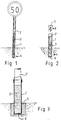
- Figure 1 shows the safety post of this invention constructed as a traffic sign post.
- the post consists of a vertical tube (1 ) with a hollow interior (2), propped up in the ground.
- the tube (1) is a thin-walled plastic shell-structure, and its bending resistance is adjusted so that the tube bends, yields and/or breaks, when submitted even to minimal lateral force.
- the hollow interior (2) of the tube (1) has been filled with granular material (3), which increases the bending resistance of the tube (1).
- the filling material (3) is massive.
- the volume weight of the filling material (3) is, preferably, and essentially, the same order of magnitude as that of mineral soil. Suitable filling materials (3) may include gravel, sand, fine sand, clay sand and/or clay.
- the hollow interior (2) of the tube (1) is only partially filled with the filling material (3) so that the filling material mostly remains at the prop-up site of the tube (1) and extends up in the tube (1) for some distance.
- the bottom end (4) of the tube (1 ) is buried into the ground.
- a traffic sign is mounted to the top end of the tube (1).
- Figure 2 shows a reflector post, i.e. so called mounted cats' eyes, which are usually set up at regular intervals along the roadside.
- the reflector sign post resembles the embodiment of Figure 1, but in this embodiment, the tube (1) is equipped with a stopper (6) to block the bottom end (4) of the tube.
- This stopper (6) prevents the filling material inside the tube from becoming damp as a consequence of humidity of the soil. If a special substance is used as the filling material, it will spoil or harden as a consequence of humidity rising from the ground.
- the tube (1 ) consists of a lid (7) which covers the top end (8) of the tube (1). By removing the lid (7), the amount of the filling material (3) can be checked and adjusted, if necessary.
- Figure 3 shows the lower end of a lamp post, which in addition to the structure discussed in Figure 1, also consists of a post erection foot (5) buried into the ground, and into which the tube (1) is mounted.
- the tube (1) is equipped with a stopper (6) which blocks the lower end (4) of the tube. This stopper (6) prevents the filling material (3) from flowing into the recess in the post erection foot (5) to which the lower end of the tube is attached.
- tube 1 consists of two successive tubes: 1 1 and 1 2 , which are joined together by their ends. There can be more than two tubes joined together. After the first tube has been erected, it can be filled with sand, after which the second tube is joined to the first, and is in turn, filled with sand etc.
- the safety post presented in Figures 1 and 2 is erected in the following manner: first, a hole is dug into the ground, and the thin-walled plastic tube (1) is driven down into the hole.
- the wall strength (1) of a plastic tube is designed so that it will bend even with minimal force.
- granular material such as sand, is poured into the hollow (2) of the tube (1). This increases the bending resistance of the tube (1) so that it withstands normal loads, such as wind, and static as well as dynamic loads caused by parts mounted to it etc.
- the post When the post is exposed to a greater than normal dynamic load, for example, a car colliding into the post, the post bends, yields or breaks easily, because granules formed by the filling material can move freely in relation to each other and the tube, and consequently the colliding vehicle is not damaged.
Landscapes
- Engineering & Computer Science (AREA)
- Architecture (AREA)
- Civil Engineering (AREA)
- Structural Engineering (AREA)
- Road Signs Or Road Markings (AREA)
Applications Claiming Priority (2)
| Application Number | Priority Date | Filing Date | Title |
|---|---|---|---|
| FI951280 | 1995-03-17 | ||
| FI951280A FI97559C (fi) | 1995-03-17 | 1995-03-17 | Turvatolppa ja menetelmä turvatolpan muodostamiseksi |
Publications (2)
| Publication Number | Publication Date |
|---|---|
| EP0735194A2 true EP0735194A2 (fr) | 1996-10-02 |
| EP0735194A3 EP0735194A3 (fr) | 1996-12-04 |
Family
ID=8543077
Family Applications (1)
| Application Number | Title | Priority Date | Filing Date |
|---|---|---|---|
| EP96660003A Withdrawn EP0735194A3 (fr) | 1995-03-17 | 1996-03-18 | Poteau de sécurité et son procédé de construction |
Country Status (2)
| Country | Link |
|---|---|
| EP (1) | EP0735194A3 (fr) |
| FI (1) | FI97559C (fr) |
Cited By (5)
| Publication number | Priority date | Publication date | Assignee | Title |
|---|---|---|---|---|
| WO2002090663A1 (fr) * | 1999-11-08 | 2002-11-14 | Automotive Safety Engineering Pty Ltd | Borne de securite |
| WO2011077392A3 (fr) * | 2009-12-22 | 2011-08-18 | Khutso Security Services (Pty) Limited | Ensemble poteau de feu de signalisation |
| DE102010038244A1 (de) | 2010-10-18 | 2012-01-19 | Dr. Ing. H.C. F. Porsche Aktiengesellschaft | Straßenbegrenzungs- oder Leitpfosten |
| GB2496896A (en) * | 2011-11-25 | 2013-05-29 | Safari Sports Ltd | A rounders post with a polyurethane foam filling |
| WO2019172325A1 (fr) * | 2018-03-08 | 2019-09-12 | 有限会社神奈川技研 | Structure de panneau de signalisation, panneau de signalisation et structure de panneau |
Families Citing this family (1)
| Publication number | Priority date | Publication date | Assignee | Title |
|---|---|---|---|---|
| FI20205552A1 (en) | 2020-05-28 | 2021-11-29 | Normiopaste Oy | SAFETY MASK |
Family Cites Families (4)
| Publication number | Priority date | Publication date | Assignee | Title |
|---|---|---|---|---|
| FR1424093A (fr) * | 1964-03-17 | 1966-01-07 | Fischer Ag Georg | Poteau de signalisation et son procédé de fixation |
| CA965573A (en) * | 1972-11-10 | 1975-04-08 | Georg Ebinger | Guide picket |
| US4078867A (en) * | 1975-12-24 | 1978-03-14 | Grandview Industries, Limited | Traffic marker post |
| US4435930A (en) * | 1980-10-14 | 1984-03-13 | Plym Oscar W | Traffic safe pole |
-
1995
- 1995-03-17 FI FI951280A patent/FI97559C/fi not_active IP Right Cessation
-
1996
- 1996-03-18 EP EP96660003A patent/EP0735194A3/fr not_active Withdrawn
Cited By (7)
| Publication number | Priority date | Publication date | Assignee | Title |
|---|---|---|---|---|
| WO2002090663A1 (fr) * | 1999-11-08 | 2002-11-14 | Automotive Safety Engineering Pty Ltd | Borne de securite |
| US7052201B2 (en) | 1999-11-08 | 2006-05-30 | Automotive Safety Engineering Pty Ltd | Safety bollard |
| WO2011077392A3 (fr) * | 2009-12-22 | 2011-08-18 | Khutso Security Services (Pty) Limited | Ensemble poteau de feu de signalisation |
| DE102010038244A1 (de) | 2010-10-18 | 2012-01-19 | Dr. Ing. H.C. F. Porsche Aktiengesellschaft | Straßenbegrenzungs- oder Leitpfosten |
| GB2496896A (en) * | 2011-11-25 | 2013-05-29 | Safari Sports Ltd | A rounders post with a polyurethane foam filling |
| WO2019172325A1 (fr) * | 2018-03-08 | 2019-09-12 | 有限会社神奈川技研 | Structure de panneau de signalisation, panneau de signalisation et structure de panneau |
| JPWO2019172325A1 (ja) * | 2018-03-08 | 2021-03-11 | 有限会社神奈川技研 | 標識柱の構造、標識柱、及び柱構造 |
Also Published As
| Publication number | Publication date |
|---|---|
| FI951280A0 (fi) | 1995-03-17 |
| FI97559C (fi) | 1997-01-10 |
| EP0735194A3 (fr) | 1996-12-04 |
| FI97559B (fi) | 1996-09-30 |
Similar Documents
| Publication | Publication Date | Title |
|---|---|---|
| US3628296A (en) | Breakaway sign support | |
| US11427976B2 (en) | Barrier system and barrier system installation method | |
| US7600942B2 (en) | Barrier device with adjustable external reinforcement structure | |
| US20220349137A1 (en) | Barrier System and Barrier System Installation Method | |
| EP0735194A2 (fr) | Poteau de sécurité et son procédé de construction | |
| US4920715A (en) | Breakaway utility pole | |
| KR20090080584A (ko) | 신호등 지지용 지주장치 | |
| KR100802095B1 (ko) | 도로 분리대용 지지대 | |
| JP7583988B2 (ja) | 耐衝撃性ボラード及び耐衝撃性ボラード用の芯材 | |
| EP0146401A2 (fr) | Procédé et dispositif pour supporter des poteaux tubulaires | |
| EP4083323B1 (fr) | Structure de support pour équipement routier | |
| US7308776B2 (en) | Pole anchor footing system | |
| WO2021150705A1 (fr) | Système de barrière et procédé d'installation de système de barrière | |
| CN210827220U (zh) | 一种公路危险地段急弯加强防护护栏 | |
| US20050076586A1 (en) | Post cover sleeve with upper vessel | |
| JP6929727B2 (ja) | 多段樹脂製マウントブロック及び車線区分柵 | |
| US6752564B1 (en) | Roadway barrier for protecting pedestrians | |
| CA3162898C (fr) | Systeme de barriere et procede d'installation de systeme de barriere | |
| RU219238U1 (ru) | Дорожное сигнальное оградительное устройство | |
| JP6872448B2 (ja) | 道路標識柱 | |
| KR100526399B1 (ko) | 충격흡수용 가드레일 겸용 난간 | |
| KR100533016B1 (ko) | 가드레일 겸용 난간 | |
| CA1300845C (fr) | Support enfoui pour poteau de voirie a base frangible | |
| KR200159633Y1 (ko) | 방호물 | |
| KR970006203Y1 (ko) | 차선 분리대 |
Legal Events
| Date | Code | Title | Description |
|---|---|---|---|
| PUAI | Public reference made under article 153(3) epc to a published international application that has entered the european phase |
Free format text: ORIGINAL CODE: 0009012 |
|
| AK | Designated contracting states |
Kind code of ref document: A2 Designated state(s): CH DE FR GB LI SE |
|
| PUAL | Search report despatched |
Free format text: ORIGINAL CODE: 0009013 |
|
| AK | Designated contracting states |
Kind code of ref document: A3 Designated state(s): CH DE FR GB LI SE |
|
| STAA | Information on the status of an ep patent application or granted ep patent |
Free format text: STATUS: THE APPLICATION IS DEEMED TO BE WITHDRAWN |
|
| 18D | Application deemed to be withdrawn |
Effective date: 19970606 |