EP0735209A1 - Profilé support transversal ou longitudinal pour revêtement de plafond - Google Patents
Profilé support transversal ou longitudinal pour revêtement de plafond Download PDFInfo
- Publication number
- EP0735209A1 EP0735209A1 EP96100395A EP96100395A EP0735209A1 EP 0735209 A1 EP0735209 A1 EP 0735209A1 EP 96100395 A EP96100395 A EP 96100395A EP 96100395 A EP96100395 A EP 96100395A EP 0735209 A1 EP0735209 A1 EP 0735209A1
- Authority
- EP
- European Patent Office
- Prior art keywords
- sheet metal
- web
- belt
- carrier
- pieces
- Prior art date
- Legal status (The legal status is an assumption and is not a legal conclusion. Google has not performed a legal analysis and makes no representation as to the accuracy of the status listed.)
- Granted
Links
- 239000002184 metal Substances 0.000 claims abstract description 92
- 238000005253 cladding Methods 0.000 claims abstract description 3
- 239000000725 suspension Substances 0.000 claims description 16
- 239000000969 carrier Substances 0.000 claims description 10
- 230000001154 acute effect Effects 0.000 claims description 4
- 125000006850 spacer group Chemical group 0.000 claims description 4
- 238000004519 manufacturing process Methods 0.000 claims description 3
- 230000000284 resting effect Effects 0.000 claims 1
- 238000010276 construction Methods 0.000 description 7
- 239000011248 coating agent Substances 0.000 description 4
- 238000000576 coating method Methods 0.000 description 4
- 238000000034 method Methods 0.000 description 2
- 238000005452 bending Methods 0.000 description 1
- 230000000295 complement effect Effects 0.000 description 1
- 239000002131 composite material Substances 0.000 description 1
- 230000007547 defect Effects 0.000 description 1
- 230000004069 differentiation Effects 0.000 description 1
- 230000002349 favourable effect Effects 0.000 description 1
- 238000007689 inspection Methods 0.000 description 1
- 239000011810 insulating material Substances 0.000 description 1
- 238000003754 machining Methods 0.000 description 1
- 238000012986 modification Methods 0.000 description 1
- 230000004048 modification Effects 0.000 description 1
- 239000011505 plaster Substances 0.000 description 1
- 230000003068 static effect Effects 0.000 description 1
- 239000011800 void material Substances 0.000 description 1
- 239000002023 wood Substances 0.000 description 1
Images




Classifications
-
- E—FIXED CONSTRUCTIONS
- E04—BUILDING
- E04B—GENERAL BUILDING CONSTRUCTIONS; WALLS, e.g. PARTITIONS; ROOFS; FLOORS; CEILINGS; INSULATION OR OTHER PROTECTION OF BUILDINGS
- E04B9/00—Ceilings; Construction of ceilings, e.g. false ceilings; Ceiling construction with regard to insulation
- E04B9/06—Ceilings; Construction of ceilings, e.g. false ceilings; Ceiling construction with regard to insulation characterised by constructional features of the supporting construction, e.g. cross section or material of framework members
- E04B9/065—Ceilings; Construction of ceilings, e.g. false ceilings; Ceiling construction with regard to insulation characterised by constructional features of the supporting construction, e.g. cross section or material of framework members comprising supporting beams having a folded cross-section
-
- E—FIXED CONSTRUCTIONS
- E04—BUILDING
- E04B—GENERAL BUILDING CONSTRUCTIONS; WALLS, e.g. PARTITIONS; ROOFS; FLOORS; CEILINGS; INSULATION OR OTHER PROTECTION OF BUILDINGS
- E04B9/00—Ceilings; Construction of ceilings, e.g. false ceilings; Ceiling construction with regard to insulation
- E04B9/06—Ceilings; Construction of ceilings, e.g. false ceilings; Ceiling construction with regard to insulation characterised by constructional features of the supporting construction, e.g. cross section or material of framework members
- E04B9/065—Ceilings; Construction of ceilings, e.g. false ceilings; Ceiling construction with regard to insulation characterised by constructional features of the supporting construction, e.g. cross section or material of framework members comprising supporting beams having a folded cross-section
- E04B9/067—Ceilings; Construction of ceilings, e.g. false ceilings; Ceiling construction with regard to insulation characterised by constructional features of the supporting construction, e.g. cross section or material of framework members comprising supporting beams having a folded cross-section with inverted T-shaped cross-section
- E04B9/068—Ceilings; Construction of ceilings, e.g. false ceilings; Ceiling construction with regard to insulation characterised by constructional features of the supporting construction, e.g. cross section or material of framework members comprising supporting beams having a folded cross-section with inverted T-shaped cross-section with double web
-
- E—FIXED CONSTRUCTIONS
- E04—BUILDING
- E04B—GENERAL BUILDING CONSTRUCTIONS; WALLS, e.g. PARTITIONS; ROOFS; FLOORS; CEILINGS; INSULATION OR OTHER PROTECTION OF BUILDINGS
- E04B9/00—Ceilings; Construction of ceilings, e.g. false ceilings; Ceiling construction with regard to insulation
- E04B9/06—Ceilings; Construction of ceilings, e.g. false ceilings; Ceiling construction with regard to insulation characterised by constructional features of the supporting construction, e.g. cross section or material of framework members
- E04B9/12—Connections between non-parallel members of the supporting construction
- E04B9/127—Connections between non-parallel members of the supporting construction one member being discontinuous and abutting against the other member
-
- E—FIXED CONSTRUCTIONS
- E04—BUILDING
- E04B—GENERAL BUILDING CONSTRUCTIONS; WALLS, e.g. PARTITIONS; ROOFS; FLOORS; CEILINGS; INSULATION OR OTHER PROTECTION OF BUILDINGS
- E04B9/00—Ceilings; Construction of ceilings, e.g. false ceilings; Ceiling construction with regard to insulation
- E04B9/18—Means for suspending the supporting construction
-
- E—FIXED CONSTRUCTIONS
- E04—BUILDING
- E04B—GENERAL BUILDING CONSTRUCTIONS; WALLS, e.g. PARTITIONS; ROOFS; FLOORS; CEILINGS; INSULATION OR OTHER PROTECTION OF BUILDINGS
- E04B9/00—Ceilings; Construction of ceilings, e.g. false ceilings; Ceiling construction with regard to insulation
- E04B9/22—Connection of slabs, panels, sheets or the like to the supporting construction
-
- E—FIXED CONSTRUCTIONS
- E04—BUILDING
- E04B—GENERAL BUILDING CONSTRUCTIONS; WALLS, e.g. PARTITIONS; ROOFS; FLOORS; CEILINGS; INSULATION OR OTHER PROTECTION OF BUILDINGS
- E04B9/00—Ceilings; Construction of ceilings, e.g. false ceilings; Ceiling construction with regard to insulation
- E04B9/22—Connection of slabs, panels, sheets or the like to the supporting construction
- E04B9/28—Connection of slabs, panels, sheets or the like to the supporting construction with the slabs, panels, sheets or the like having grooves engaging with horizontal flanges of the supporting construction or accessory means connected thereto
Definitions
- the invention relates to longitudinal or transverse beams for a support structure, which are formed essentially from T-shaped, angled sheets, for a ceiling cladding from adjacent, forming a surface grid and each insertable between two parallel beams and detachably held on these ceiling plates.
- Such inlay constructions are known, for example, from the company publication "Konstrutation 200” from Suckow + Fischer GmbH, where they are designed for holding ceiling panels made of plaster, metal, pressed wood shavings and the like, which on the cross straps of longitudinal and cross members clear dimensions between their webs are just filling, laid on.
- the folded profiles should not overlap the webs as much as possible, so that the width of the ceiling plates that can be used is used Cross belts are not unnecessarily restricted.
- the folds from the level of the webs are therefore equally wide on each side, so that the web edge at the zenith of the folded profile is exactly in the center; this is necessary at least for the beams if the insert construction is hung there on the folding profiles, the suspensions being introduced into the interior of the respective folding profile through the gap.
- the central arrangement of the zenith on the support profile ensures that no torques can attack the supports.
- the invention has set itself the task of executing a carrier of the type described in more detail above for a holding structure with components that are easy to manufacture, in which the grid joints of the surface grid can be kept very narrow and instead are formed by the ceiling plates themselves instead of the carrier are to be individually assembled and disassembled and which can form a variable grid, at least between very dimensionally stable beams.
- the entire carrier should largely do without machining and integral connections in order to maintain an, for example, galvanic coating of its components intact.
- the object is first achieved in that the supports each consist of a T-shaped base sheet metal body and a stiffening sheet metal body, the base sheet metal body in one piece from a T-shape forming double-walled belt and a double-walled adjoining it
- the web and the web are angled from a single first sheet metal strip to form a (horizontal) adjacent outer and two inner web strips and two (vertical) adjacent web strips
- the belt is encased by the stiffening sheet metal body and the stiffening sheet metal body is composed of a single, sheet metal angled to form the belt
- the parallel edges of the first sheet metal strip together the free edge of the web form and the parallel edges of the second sheet metal strip are in the double-sided longitudinal gussets between the web and the belt.
- Such a carrier can be produced without difficulty from a galvanically coated sheet of metal, without the coating having to be locally damaged by punched-out perforations or spot welds or other defects.
- the strap of the carrier can be produced by the applied stiffening sheet metal body with a particularly high proportion of the total moment of resistance of the carrier and at the same time is already extremely dimensionally stable on its own.
- the invention is further characterized in that the edges of the first sheet metal strip are angled toward horizontal first guide grooves pointing away from the web, in which guide pieces for the ceiling panels which are displaceable along the support are guided.
- the guide grooves have a semicircular cross section, because this can be easily shaped and enables the holding pieces to be guided reliably without them being able to clamp on the supports.
- Another management of the holding pieces is created by the fact that the edges of the second sheet metal strip each end at a distance from the web and the holding pieces are guided in the second guide grooves formed in this way on both sides of the web and adjoining the belt and each delimited by one of the edges and the web. In this way, they can be moved along their carrier as desired and brought into a position in which a component is to be connected to the carrier.
- the holding pieces suitably each consist of a flat piece of sheet metal and at least one holding element fastened to the sheet piece for the associated ceiling plate; the holding element can also be releasably attached to the sheet metal piece.
- the generally flat piece of sheet metal remains in place when the component connected to it is installed, without it having to be connected to the carrier other than via the two guide grooves.
- the entire arrangement of the holding structure is extremely dimensionally stable if the ceiling plate can be positively connected to the holding element; for this purpose, the holding element can be designed in the form of a bolt and protrude into the spatial area of the associated ceiling plate. It goes without saying that this ceiling plate must have corresponding recesses or other shaped elements which correspond to the holding element in a form-fitting manner.
- Such connections are possible in a variety of designs; It is particularly advantageous if they can be easily detached by changing the position of the components involved, so that the ceiling plate can be removed comfortably from the holding structure. The details of such connections are common in the art.
- cross members for example, can still be easily connected to the side members; for this purpose, tab pieces can be guided in the same guide grooves as for the holding pieces, to which cross members of this type can be connected, which are then clamped between the beams.
- Cross members may be required if the clear width of the ceiling panels turns out to be too large, in particular also if, as will be explained below, the carriers are provided in a reverse T-shape with overlying ceiling panels, as is known from DE utility model 94 13 816 is.
- the ceiling panels can each be angled from a sheet metal blank, in particular in such a way that they each consist of a flat, horizontal, preferably rectangular surface piece facing the room, coordinated with the surface grid, and edge pieces angled at all angles in the area of the supports; the ceiling panels are particularly dimensionally stable if the edge pieces are joined together at their abutting edges.
- the area grid is therefore formed by the surface pieces of the ceiling panels, especially if they end below the beams, while the edge pieces can also be used for locking.
- the ceiling panels are box-shaped and can, if necessary still be filled with insulating material; As a rule, however, a later coating of the surface pieces is sufficient, for example to design an acoustic ceiling.
- the supports according to the invention are particularly advantageous if flanges are formed on the ceiling panels at their edge pieces running transversely to the supports, preferably in one piece with them, and are designed such that they can be placed on top of one another and one of the abutting ceiling panels is supported on the one hand on another, adjacent one and on the other hand supports a third neighboring one.
- the ceiling panels are nevertheless securely supported because they rest on three sides.
- the stability on its fourth side, which supports the adjacent ceiling panel can be improved in that the ceiling panel on this side is supported on the adjacent supports by at least one holding piece on both sides.
- a uniform joint width between the ceiling tiles results in a simple manner if the flanged edge pieces of adjacent ceiling tiles strike on both sides of a spacer attached to at least one of the associated beams, for which it is also sufficient if it is only temporarily and provisionally provided and even with the beam has not been firmly connected.
- the mutual support of the ceiling panels is possible in that the flanges are formed as continuous, flat sheet metal tabs on the edge pieces, which in the same in the case of abutting edge pieces Show direction.
- a ceiling tile lies on an adjacent one, but can be lifted upwards. Therefore, the arrangement of a ceiling plate on the holding piece can be made such that the ceiling plate is pivotable about the holding elements located on the sheet metal pieces of these holding pieces.
- the described design of the carrier is primarily intended for a holding structure in which the straps of the carrier are oriented overhead. It is, however, deviating from this, as with the previously known holding structure, that the carriers are arranged so that their belts serve as a support for the ceiling panels. With such an arrangement, a suspension of the carriers can be carried out very easily by providing openings, such as slots or the like, in the webs of the carriers, in which suspensions can be locked for the carriers. It is particularly favorable if the suspensions run into flat retaining tabs that can be inserted into the double-walled web of the respective carrier and are provided with integrally molded spring pieces that engage in the openings so that they fix the carrier in the process.
- a support structure with beams according to the invention leads to a very light construction, which also reduces the overall load on the ceiling.
- a carrier of this type which consists of a T-shape, a single, double-walled, angled first sheet metal strip, each with a horizontal belt and a perpendicular web that adjoins this at right angles, and a basic sheet metal body that covers the belt on both sides, on the other Belt strips each flat stiffening sheet metal body consists of a single, the belt angled to form a second sheet metal strip, wherein the parallel edges of the first sheet metal strip together form the free edge of the web and the parallel edges of the second sheet metal strip in the double-sided longitudinal gussets between the web and the belt, can be produced according to the invention in that the base sheet metal body is first produced from the first sheet metal strip in such a way that the two inner belt strips adjoining the web, of the double-walled belt only so far from the outer belt strip and de n web strips are angled, that the web strips form an acute angle with each other in contact with the edges and the inner belt strips with the outer belt strip, and that the second sheet metal strip is then formed over the belt
- the base plate body is not initially brought into its final shape; this takes place only through the stiffening sheet metal body deformed above it, so that the superimposed surfaces of both sheet metal bodies are braced against one another under considerable pretension and in this way ensure a stiffening sheet metal body which is extremely firmly attached to the base sheet metal body, even when the remaining The elasticity of the sheet used is not high.
- the base sheet metal body of the carrier thus also receives its final shape only after it has been connected to the stiffening sheet metal body.
- a carrier according to the invention is used to hold ceiling panels 1 (1 ', 1''), which are inserted according to FIG. 1 into an area grid R and are held according to FIGS. 2 and 3 on carriers 2, which are parallel to each other from a room wall to others are sufficient and are either attached to the ceiling above or attached to the walls of the room.
- Very narrow grid joints F are formed between the ceiling panels 1, the joint width b of which depends along the support 2 on the construction of the support 2 to be described and transversely for this purpose from spacers D (FIG. 3), which are provided on the supports 2, at least temporarily.
- the ceiling panels 1 (1 ') are box-shaped by angled on a flat, the surface pattern R defining surface piece 11 on all sides edge pieces 12 and the height h (Fig. 4) determine the respective ceiling tile 1.
- two end edge pieces 12a are provided for holding the ceiling plate 1 on the two supports 2, between which the ceiling plate 1 is clamped, while the longitudinal edge pieces 12b and 12c 'provide mutual support for two adjacent, abutting ceiling plates 1, 1' (Fig 4) serve.
- the reference numerals of the rear ceiling plate in FIG. 4 are noted for a better differentiation.
- the details of the carrier 2 can be seen particularly well in FIGS. 2 and 4 to 6. It consists of formed sheet metal strips 210 and 220 in a composite construction of a base sheet metal body 21 and a stiffening sheet metal body 22.
- a first sheet metal strip 210 is angled several times to form a double-walled belt 21a and a web 21b which is also integral and also double-walled on the belt 21a, the belt 21a and the web 21b being initially preformed in accordance with FIG. 5 such that those directed towards the web 21b inner belt strips 21a, i with the outer belt strips 21a, ä forming the upper end of the sheet metal base body 21 each include an acute angle w1 and the web strips 21b, s enclose an acute angle w2.
- the base sheet metal body 21 is angled such that the free edges 210a of the first sheet metal strip 210 end at the end of the web 21b facing away from the belt 21a and run parallel to one another. They are each formed into a semicircular cross-section HK which is open at the top, so that a first guide groove N1 is formed on each side of the web 21b. 5 that the guide grooves N1 are used for parallel, parallel guidance on the support 2 of a holding piece 3 to which a ceiling plate 1 can be attached.
- a holding piece 3 consists of a flat piece of sheet metal 31, to which a holding element 32, which projects into the spatial area of the ceiling plate 1 to be held, is fastened.
- the second guide groove N2 arises from the fact that the edges 220a of the second sheet metal strip 220 do not extend to the web strips 21b, s of the web 21b, so that the guide grooves N2 each have an edge 220a, a web strip 21b, s and an inner belt strip 21a , i are limited. It goes without saying that it is expedient to arrange the holding piece 3 with clearance in the guide of the guide grooves N1, N2, so that they can be introduced into the guide without difficulty.
- the second sheet metal strip 220 is angled toward the stiffening sheet metal body 22, as is particularly illustrated in FIG. 5.
- the initially provisional bending of the base sheet metal body 21 with the angles w1 and w2 is brought into the final shape by the application of the stiffening sheet metal body 22, in which the Angles w1 and w2 disappear.
- the edges 220a press the longitudinal gusset to its permanent 90 ° shape.
- the holding elements 32 are shown as bolts which each reach into a hole punched in the side wall of the plate and rotatably support the plate so that it can be swung down from the ceiling level and inspection openings for Uncover ceiling void.
- Other connecting parts or connecting elements instead of the holding element 32 are also possible, a positive engagement always being to take place. However, it is expedient if the positive connection can be released in the event that the relevant ceiling plate 1 is to be removed from the holding structure.
- Cross beams between the longitudinal beams 2 for supporting the ceiling panels are usually superfluous in a support structure according to the invention.
- a flange 12d, 12e ' is angled at each of the adjacent edge pieces 12b, 12c' (FIG. 4), in such a way that they point in the same direction and lie flat on one another when the ceiling panels 1,1 'are mounted, the support flange 12e 'rests on the support flange 12d, in the vicinity of which the ceiling plate 1 rests on the holding elements 32 on both sides.
- the support elements on the ceiling plate 1 which are complementary to the holding elements 32 and omitted in the drawing should, as mentioned, make it possible to release the positive connection with the holding elements 32 if the ceiling plates 1, 1 'and in particular the ceiling plate 1' mutually and around the holding elements 32 are pivoted and the flanges 12d, 12e 'come out of engagement. It is then ensured that each individual ceiling tile 1 can be removed from the support structure without changing anything else.
- the pivotability of the ceiling panels 1 is improved if the flanges 12d, 12e 'are bounded by notches 12f (FIG. 2) and the height of the edge pieces 12a is as low as possible, as shown in FIGS. 2 to 4.
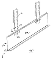
- Fig. 7 shows that the carrier 2 can also be reversed T-shaped, so that their straps 21a serve as a base for the ceiling panels omitted in the drawing and the webs 21b for fastening the carrier 2 on appropriately designed suspensions 4.
- Fig. 7 also shows that the web strips 21b, s in the area of the suspension 4 are slightly widened by this; this can be limited to such an extent that there is again no fear of obstruction of the holding pieces 3.
- the hanger 5 consists of a bent sheet metal strip 51, from which a tongue 52 is bent, which runs parallel to a section 53 of the carrier 2. This tongue 52 engages in the guide groove N1 of the carrier.
- the second section 54 of the hanger 5 engages in the groove N2 of the carrier 2, the distance between the end 54 and the tongue 52 essentially corresponding to the height of the carrier 2.
- the hanger 5 is then usually attached to the substructure.
- FIG. 9a show a perspective view of a ceiling which is fastened by means of the support 2 and hanger 5 according to the invention.
- the upper ends 55 of the length-adjustable hangers are attached to a substructure or a ceiling plate.
- the right-angled connection of the carrier 2 is advantageously carried out with corner elements 6, which are also inserted into the opposite guide grooves N1 and N2.
- the ceiling plate 1 can also be placed on the lower flange of the support 2 (FIG. 9).
Landscapes
- Engineering & Computer Science (AREA)
- Architecture (AREA)
- Physics & Mathematics (AREA)
- Electromagnetism (AREA)
- Civil Engineering (AREA)
- Structural Engineering (AREA)
- Finishing Walls (AREA)
- Rod-Shaped Construction Members (AREA)
- Joining Of Building Structures In Genera (AREA)
- Roof Covering Using Slabs Or Stiff Sheets (AREA)
- Vehicle Interior And Exterior Ornaments, Soundproofing, And Insulation (AREA)
Applications Claiming Priority (2)
| Application Number | Priority Date | Filing Date | Title |
|---|---|---|---|
| DE19510741 | 1995-03-24 | ||
| DE19510741A DE19510741A1 (de) | 1995-03-24 | 1995-03-24 | Längs- oder Querträger für eine Deckenverkleidung |
Publications (2)
| Publication Number | Publication Date |
|---|---|
| EP0735209A1 true EP0735209A1 (fr) | 1996-10-02 |
| EP0735209B1 EP0735209B1 (fr) | 2001-08-01 |
Family
ID=7757579
Family Applications (1)
| Application Number | Title | Priority Date | Filing Date |
|---|---|---|---|
| EP96100395A Expired - Lifetime EP0735209B1 (fr) | 1995-03-24 | 1996-01-12 | Profilé support transversal ou longitudinal pour revêtement de plafond |
Country Status (6)
| Country | Link |
|---|---|
| US (1) | US5732521A (fr) |
| EP (1) | EP0735209B1 (fr) |
| JP (1) | JPH08338099A (fr) |
| KR (1) | KR960034614A (fr) |
| AT (1) | ATE203793T1 (fr) |
| DE (2) | DE19510741A1 (fr) |
Families Citing this family (16)
| Publication number | Priority date | Publication date | Assignee | Title |
|---|---|---|---|---|
| US6205733B1 (en) | 1999-07-27 | 2001-03-27 | Usg Interiors, Inc. | Direct mount ceiling panel grid system |
| IT1318031B1 (it) | 2000-06-20 | 2003-07-21 | Sadi S P A | Sistema di sospensione per pannelli di controsoffitti |
| SG129997A1 (en) * | 2001-02-26 | 2007-03-20 | Armstrong World Ind Inc | Ceiling grid system |
| US7076928B2 (en) * | 2002-02-04 | 2006-07-18 | Owens Corning Fiberglas Technology, Inc. | Suspended ceiling panel edge and rib technology |
| US20030213200A1 (en) * | 2002-05-17 | 2003-11-20 | Wood Creations, Inc. | Method for installing a faux wood ceiling and apparatus for use therein |
| US6729096B1 (en) * | 2002-09-09 | 2004-05-04 | Aaon Inc. | System for installing suspended ceiling |
| US20060005495A1 (en) * | 2004-07-12 | 2006-01-12 | Wilfried Stessel | Concealed accessible suspended ceiling system |
| US20070175152A1 (en) * | 2005-12-20 | 2007-08-02 | Kupec Thoms F | Single strip - double web ceiling grid member |
| US20070028554A1 (en) * | 2005-08-05 | 2007-02-08 | James Ferrell | High strength runner |
| US7516585B2 (en) * | 2005-11-21 | 2009-04-14 | Usg Interiors, Inc. | Grid tee for suspension ceiling |
| US7578107B2 (en) * | 2005-12-02 | 2009-08-25 | Worthington Armstrong Venture | Suspended ceiling segment |
| US7673430B1 (en) * | 2006-08-10 | 2010-03-09 | Koninklijke Philips Electronics, N.V | Recessed wall-wash staggered mounting system |
| US7841149B2 (en) * | 2006-10-16 | 2010-11-30 | Chicago Metallic Corporation | Concealed ceiling panel system |
| US7703254B2 (en) * | 2007-10-08 | 2010-04-27 | Alderman Robert J | Reflective insulation tiles |
| CA2874877A1 (fr) * | 2014-12-15 | 2016-06-15 | Petrovic Zeljko | Plafonds e-zel cs |
| CN105201119B (zh) * | 2015-09-30 | 2017-07-28 | 浙江亚厦装饰股份有限公司 | 一种组合式t型龙骨 |
Citations (11)
| Publication number | Priority date | Publication date | Assignee | Title |
|---|---|---|---|---|
| GB822043A (en) * | 1955-10-25 | 1959-10-21 | Anders Palmer | Improvements in or relating to suspension means for ceiling plates |
| FR1207244A (fr) * | 1957-10-10 | 1960-02-15 | Phenix Works Sa | Panneaux de revêtement et leurs moyens de fixation |
| FR76130E (fr) * | 1958-10-10 | 1961-09-15 | Phenix Works Sa | Panneaux de revêtement et leurs moyens de fixation |
| FR2206425A1 (fr) * | 1972-11-15 | 1974-06-07 | Philips Nv | |
| FR2549933A1 (fr) * | 1983-07-27 | 1985-02-01 | Donn France Sa | Poutre profilee en forme d'i, attaches et assemblages pour de telles poutres |
| US4554718A (en) * | 1984-06-04 | 1985-11-26 | Armstrong World Industries, Inc. | Method of reinforcing a ceiling runner |
| EP0237651A1 (fr) * | 1986-03-19 | 1987-09-23 | Chicago Metallic Continental N.V. | Poutrelle pour plafond suspendu, faux-plafond à résilles obtenu par ce moyen et connecteurs utilisés à cet effet |
| US4817357A (en) * | 1987-12-21 | 1989-04-04 | Donn Incorporated | Suspension ceiling grid tee |
| US4852325A (en) * | 1987-10-26 | 1989-08-01 | Chicago Metallic Corporation | Reinforced bead |
| US4932186A (en) * | 1989-04-06 | 1990-06-12 | Chicago Metallic Corporation | Reinforced bead |
| US5088261A (en) * | 1990-12-20 | 1992-02-18 | Usg Interiors, Inc. | Curved grid tees for suspension ceilings |
Family Cites Families (7)
| Publication number | Priority date | Publication date | Assignee | Title |
|---|---|---|---|---|
| US3276179A (en) * | 1964-05-11 | 1966-10-04 | James M Rallis | Ceiling access opening and bracket therefor |
| ES279463Y (es) * | 1984-05-24 | 1985-06-01 | Andia Louvers S.A. | Dispositivo para la sujeccion de perfiles para techo de celosia de suspension oculta |
| US4678487A (en) * | 1985-05-14 | 1987-07-07 | Flanders Filters, Inc. | Laminar flow clean room having improved filter bank |
| DE3525139A1 (de) * | 1985-07-13 | 1987-01-15 | Richter System Gmbh & Co Kg | Tragschiene fuer unterdecken |
| US4949517A (en) * | 1989-12-27 | 1990-08-21 | Blitzer Jacob H | Wire grid subceiling panel |
| US5050360A (en) * | 1990-04-18 | 1991-09-24 | Alcan Aluminum Corporation | Suspended ceiling panel |
| DE9413816U1 (de) * | 1994-08-26 | 1994-12-01 | Suckow + Fischer GmbH, 64584 Biebesheim | Einlegekonstruktion für eine Deckenverkleidung |
-
1995
- 1995-03-24 DE DE19510741A patent/DE19510741A1/de not_active Withdrawn
-
1996
- 1996-01-12 AT AT96100395T patent/ATE203793T1/de not_active IP Right Cessation
- 1996-01-12 DE DE59607387T patent/DE59607387D1/de not_active Expired - Fee Related
- 1996-01-12 EP EP96100395A patent/EP0735209B1/fr not_active Expired - Lifetime
- 1996-03-21 JP JP8064613A patent/JPH08338099A/ja active Pending
- 1996-03-22 US US08/620,440 patent/US5732521A/en not_active Expired - Fee Related
- 1996-03-23 KR KR1019960008004A patent/KR960034614A/ko not_active Withdrawn
Patent Citations (11)
| Publication number | Priority date | Publication date | Assignee | Title |
|---|---|---|---|---|
| GB822043A (en) * | 1955-10-25 | 1959-10-21 | Anders Palmer | Improvements in or relating to suspension means for ceiling plates |
| FR1207244A (fr) * | 1957-10-10 | 1960-02-15 | Phenix Works Sa | Panneaux de revêtement et leurs moyens de fixation |
| FR76130E (fr) * | 1958-10-10 | 1961-09-15 | Phenix Works Sa | Panneaux de revêtement et leurs moyens de fixation |
| FR2206425A1 (fr) * | 1972-11-15 | 1974-06-07 | Philips Nv | |
| FR2549933A1 (fr) * | 1983-07-27 | 1985-02-01 | Donn France Sa | Poutre profilee en forme d'i, attaches et assemblages pour de telles poutres |
| US4554718A (en) * | 1984-06-04 | 1985-11-26 | Armstrong World Industries, Inc. | Method of reinforcing a ceiling runner |
| EP0237651A1 (fr) * | 1986-03-19 | 1987-09-23 | Chicago Metallic Continental N.V. | Poutrelle pour plafond suspendu, faux-plafond à résilles obtenu par ce moyen et connecteurs utilisés à cet effet |
| US4852325A (en) * | 1987-10-26 | 1989-08-01 | Chicago Metallic Corporation | Reinforced bead |
| US4817357A (en) * | 1987-12-21 | 1989-04-04 | Donn Incorporated | Suspension ceiling grid tee |
| US4932186A (en) * | 1989-04-06 | 1990-06-12 | Chicago Metallic Corporation | Reinforced bead |
| US5088261A (en) * | 1990-12-20 | 1992-02-18 | Usg Interiors, Inc. | Curved grid tees for suspension ceilings |
Also Published As
| Publication number | Publication date |
|---|---|
| EP0735209B1 (fr) | 2001-08-01 |
| ATE203793T1 (de) | 2001-08-15 |
| KR960034614A (ko) | 1996-10-24 |
| DE19510741A1 (de) | 1996-09-26 |
| US5732521A (en) | 1998-03-31 |
| JPH08338099A (ja) | 1996-12-24 |
| DE59607387D1 (de) | 2001-09-06 |
Similar Documents
| Publication | Publication Date | Title |
|---|---|---|
| DE3728873C2 (de) | Aufhängevorrichtung für Zimmerdecken mit einschnappbaren Paneelen | |
| DE3434999C2 (de) | Traggitter für eine abgehängte Decke | |
| DE10136681A1 (de) | Rahmengestell | |
| DE3139829A1 (de) | Pfosten fuer eine demontierbare trennwand | |
| EP0735209B1 (fr) | Profilé support transversal ou longitudinal pour revêtement de plafond | |
| DE29917734U1 (de) | Aus einem Profilelement gebildete Montageschiene | |
| DE3442509A1 (de) | Rechteckige bodenplatte fuer hochliegende trag- oder fussboeden, gitter fuer eine derartige bodenplatte und verfahren zur herstellung eines solchen gitters | |
| AT408374B (de) | Plattenförmiges strangpressprofil | |
| WO2000040874A1 (fr) | Canal de guidage | |
| DE3247506C2 (de) | Gasdichte Unterdecke | |
| EP0217268A2 (fr) | Elément de plafond rectangulaire pour un faux plafond | |
| DE29509555U1 (de) | Schaltschrank mit Montageplatte als Einzel- oder Anreihschrank | |
| EP0465905A1 (fr) | Revêtement de plafond | |
| DE29901412U1 (de) | Lochrasterplatte, insbesondere für Textilien-Transportfahrzeuge, Container, Behälter und Aufbauten jeglicher Art | |
| DE1292355B (de) | Verbindung von an einem beidseitig abstehenden Flansch eines Traegers anliegenden und dort gestossenen Decken- oder Wandplatten mit dem Traeger | |
| DE102022125081B3 (de) | Bodenstütze eines Kabeltragsystems | |
| DE9013711U1 (de) | Regalboden mit durch Abkantungen gebildeten Versteifungsprofilen | |
| EP0427948B1 (fr) | Suspente pour profilés en C | |
| EP4595174A1 (fr) | Support plancher d'un système de support de câble | |
| DE2065838C3 (de) | Vorrichtung zum Abstützen von die äußere Schale eines zweischaligen Flachdaches bildenden Dacheindeckungsplatten | |
| AT397125B (de) | Verschluss für öffnungen in raum- oder zwischendecken | |
| DE2543950C2 (de) | U-formiges Bauelement | |
| DE60019973T2 (de) | Hohles profil | |
| EP2226272B1 (fr) | Système d'étagère | |
| DE2640555A1 (de) | Haengedecke |
Legal Events
| Date | Code | Title | Description |
|---|---|---|---|
| PUAI | Public reference made under article 153(3) epc to a published international application that has entered the european phase |
Free format text: ORIGINAL CODE: 0009012 |
|
| AK | Designated contracting states |
Kind code of ref document: A1 Designated state(s): AT BE CH DE DK ES FR GB IT LI NL PT SE |
|
| 17P | Request for examination filed |
Effective date: 19960927 |
|
| RAP1 | Party data changed (applicant data changed or rights of an application transferred) |
Owner name: SUCKOW + FISCHER GMBH Owner name: WILHELMI WERKE AKTIENGESELLSCHAFT |
|
| 17Q | First examination report despatched |
Effective date: 19990922 |
|
| GRAG | Despatch of communication of intention to grant |
Free format text: ORIGINAL CODE: EPIDOS AGRA |
|
| GRAG | Despatch of communication of intention to grant |
Free format text: ORIGINAL CODE: EPIDOS AGRA |
|
| GRAH | Despatch of communication of intention to grant a patent |
Free format text: ORIGINAL CODE: EPIDOS IGRA |
|
| GRAH | Despatch of communication of intention to grant a patent |
Free format text: ORIGINAL CODE: EPIDOS IGRA |
|
| GRAA | (expected) grant |
Free format text: ORIGINAL CODE: 0009210 |
|
| AK | Designated contracting states |
Kind code of ref document: B1 Designated state(s): AT BE CH DE DK ES FR GB IT LI NL PT SE |
|
| PG25 | Lapsed in a contracting state [announced via postgrant information from national office to epo] |
Ref country code: NL Free format text: LAPSE BECAUSE OF FAILURE TO SUBMIT A TRANSLATION OF THE DESCRIPTION OR TO PAY THE FEE WITHIN THE PRESCRIBED TIME-LIMIT Effective date: 20010801 Ref country code: IT Free format text: LAPSE BECAUSE OF FAILURE TO SUBMIT A TRANSLATION OF THE DESCRIPTION OR TO PAY THE FEE WITHIN THE PRE;WARNING: LAPSES OF ITALIAN PATENTS WITH EFFECTIVE DATE BEFORE 2007 MAY HAVE OCCURRED AT ANY TIME BEFORE 2007. THE CORRECT EFFECTIVE DATE MAY BE DIFFERENT FROM THE ONE RECORDED.SCRIBED TIME-LIMIT Effective date: 20010801 Ref country code: GB Free format text: LAPSE BECAUSE OF FAILURE TO SUBMIT A TRANSLATION OF THE DESCRIPTION OR TO PAY THE FEE WITHIN THE PRESCRIBED TIME-LIMIT Effective date: 20010801 Ref country code: FR Free format text: LAPSE BECAUSE OF FAILURE TO SUBMIT A TRANSLATION OF THE DESCRIPTION OR TO PAY THE FEE WITHIN THE PRESCRIBED TIME-LIMIT Effective date: 20010801 |
|
| REF | Corresponds to: |
Ref document number: 203793 Country of ref document: AT Date of ref document: 20010815 Kind code of ref document: T |
|
| REG | Reference to a national code |
Ref country code: CH Ref legal event code: EP |
|
| REF | Corresponds to: |
Ref document number: 59607387 Country of ref document: DE Date of ref document: 20010906 |
|
| PG25 | Lapsed in a contracting state [announced via postgrant information from national office to epo] |
Ref country code: SE Free format text: LAPSE BECAUSE OF FAILURE TO SUBMIT A TRANSLATION OF THE DESCRIPTION OR TO PAY THE FEE WITHIN THE PRESCRIBED TIME-LIMIT Effective date: 20011101 Ref country code: DK Free format text: LAPSE BECAUSE OF FAILURE TO SUBMIT A TRANSLATION OF THE DESCRIPTION OR TO PAY THE FEE WITHIN THE PRESCRIBED TIME-LIMIT Effective date: 20011101 |
|
| PG25 | Lapsed in a contracting state [announced via postgrant information from national office to epo] |
Ref country code: PT Free format text: LAPSE BECAUSE OF FAILURE TO SUBMIT A TRANSLATION OF THE DESCRIPTION OR TO PAY THE FEE WITHIN THE PRESCRIBED TIME-LIMIT Effective date: 20011105 |
|
| EN | Fr: translation not filed | ||
| NLV1 | Nl: lapsed or annulled due to failure to fulfill the requirements of art. 29p and 29m of the patents act | ||
| PG25 | Lapsed in a contracting state [announced via postgrant information from national office to epo] |
Ref country code: AT Free format text: LAPSE BECAUSE OF NON-PAYMENT OF DUE FEES Effective date: 20020112 |
|
| GBV | Gb: ep patent (uk) treated as always having been void in accordance with gb section 77(7)/1977 [no translation filed] |
Effective date: 20010801 |
|
| PG25 | Lapsed in a contracting state [announced via postgrant information from national office to epo] |
Ref country code: LI Free format text: LAPSE BECAUSE OF NON-PAYMENT OF DUE FEES Effective date: 20020131 Ref country code: CH Free format text: LAPSE BECAUSE OF NON-PAYMENT OF DUE FEES Effective date: 20020131 Ref country code: BE Free format text: LAPSE BECAUSE OF NON-PAYMENT OF DUE FEES Effective date: 20020131 |
|
| PG25 | Lapsed in a contracting state [announced via postgrant information from national office to epo] |
Ref country code: ES Free format text: LAPSE BECAUSE OF FAILURE TO SUBMIT A TRANSLATION OF THE DESCRIPTION OR TO PAY THE FEE WITHIN THE PRESCRIBED TIME-LIMIT Effective date: 20020228 |
|
| PLBE | No opposition filed within time limit |
Free format text: ORIGINAL CODE: 0009261 |
|
| STAA | Information on the status of an ep patent application or granted ep patent |
Free format text: STATUS: NO OPPOSITION FILED WITHIN TIME LIMIT |
|
| 26N | No opposition filed | ||
| BERE | Be: lapsed |
Owner name: SUCKOW + FISCHER G.M.B.H. Effective date: 20020131 Owner name: WILHELMI WERKE A.G. Effective date: 20020131 |
|
| REG | Reference to a national code |
Ref country code: CH Ref legal event code: PL |
|
| PGFP | Annual fee paid to national office [announced via postgrant information from national office to epo] |
Ref country code: DE Payment date: 20050316 Year of fee payment: 10 |
|
| PG25 | Lapsed in a contracting state [announced via postgrant information from national office to epo] |
Ref country code: DE Free format text: LAPSE BECAUSE OF NON-PAYMENT OF DUE FEES Effective date: 20060801 |