EP0735249B1 - Ventilsteuervorrichtung - Google Patents
Ventilsteuervorrichtung Download PDFInfo
- Publication number
- EP0735249B1 EP0735249B1 EP96301979A EP96301979A EP0735249B1 EP 0735249 B1 EP0735249 B1 EP 0735249B1 EP 96301979 A EP96301979 A EP 96301979A EP 96301979 A EP96301979 A EP 96301979A EP 0735249 B1 EP0735249 B1 EP 0735249B1
- Authority
- EP
- European Patent Office
- Prior art keywords
- arm
- valve
- rocker arm
- rocker
- engagement
- Prior art date
- Legal status (The legal status is an assumption and is not a legal conclusion. Google has not performed a legal analysis and makes no representation as to the accuracy of the status listed.)
- Expired - Lifetime
Links
- 238000002485 combustion reaction Methods 0.000 claims description 3
- 230000006835 compression Effects 0.000 claims description 2
- 238000007906 compression Methods 0.000 claims description 2
- 230000003068 static effect Effects 0.000 description 3
- 238000005086 pumping Methods 0.000 description 2
- 238000006243 chemical reaction Methods 0.000 description 1
- 238000010276 construction Methods 0.000 description 1
- 230000014759 maintenance of location Effects 0.000 description 1
- 238000004519 manufacturing process Methods 0.000 description 1
Images

Classifications
-
- F—MECHANICAL ENGINEERING; LIGHTING; HEATING; WEAPONS; BLASTING
- F01—MACHINES OR ENGINES IN GENERAL; ENGINE PLANTS IN GENERAL; STEAM ENGINES
- F01L—CYCLICALLY OPERATING VALVES FOR MACHINES OR ENGINES
- F01L13/00—Modifications of valve-gear to facilitate reversing, braking, starting, changing compression ratio, or other specific operations
- F01L13/0005—Deactivating valves
-
- F—MECHANICAL ENGINEERING; LIGHTING; HEATING; WEAPONS; BLASTING
- F01—MACHINES OR ENGINES IN GENERAL; ENGINE PLANTS IN GENERAL; STEAM ENGINES
- F01L—CYCLICALLY OPERATING VALVES FOR MACHINES OR ENGINES
- F01L1/00—Valve-gear or valve arrangements, e.g. lift-valve gear
- F01L1/12—Transmitting gear between valve drive and valve
- F01L1/18—Rocking arms or levers
- F01L1/185—Overhead end-pivot rocking arms
-
- F—MECHANICAL ENGINEERING; LIGHTING; HEATING; WEAPONS; BLASTING
- F01—MACHINES OR ENGINES IN GENERAL; ENGINE PLANTS IN GENERAL; STEAM ENGINES
- F01L—CYCLICALLY OPERATING VALVES FOR MACHINES OR ENGINES
- F01L1/00—Valve-gear or valve arrangements, e.g. lift-valve gear
- F01L1/20—Adjusting or compensating clearance
- F01L1/22—Adjusting or compensating clearance automatically, e.g. mechanically
- F01L1/24—Adjusting or compensating clearance automatically, e.g. mechanically by fluid means, e.g. hydraulically
- F01L1/2405—Adjusting or compensating clearance automatically, e.g. mechanically by fluid means, e.g. hydraulically by means of a hydraulic adjusting device located between the cylinder head and rocker arm
-
- F—MECHANICAL ENGINEERING; LIGHTING; HEATING; WEAPONS; BLASTING
- F01—MACHINES OR ENGINES IN GENERAL; ENGINE PLANTS IN GENERAL; STEAM ENGINES
- F01L—CYCLICALLY OPERATING VALVES FOR MACHINES OR ENGINES
- F01L13/00—Modifications of valve-gear to facilitate reversing, braking, starting, changing compression ratio, or other specific operations
- F01L13/0015—Modifications of valve-gear to facilitate reversing, braking, starting, changing compression ratio, or other specific operations for optimising engine performances by modifying valve lift according to various working parameters, e.g. rotational speed, load, torque
- F01L13/0036—Modifications of valve-gear to facilitate reversing, braking, starting, changing compression ratio, or other specific operations for optimising engine performances by modifying valve lift according to various working parameters, e.g. rotational speed, load, torque the valves being driven by two or more cams with different shape, size or timing or a single cam profiled in axial and radial direction
-
- F—MECHANICAL ENGINEERING; LIGHTING; HEATING; WEAPONS; BLASTING
- F01—MACHINES OR ENGINES IN GENERAL; ENGINE PLANTS IN GENERAL; STEAM ENGINES
- F01L—CYCLICALLY OPERATING VALVES FOR MACHINES OR ENGINES
- F01L1/00—Valve-gear or valve arrangements, e.g. lift-valve gear
- F01L1/12—Transmitting gear between valve drive and valve
- F01L1/18—Rocking arms or levers
- F01L2001/186—Split rocking arms, e.g. rocker arms having two articulated parts and means for varying the relative position of these parts or for selectively connecting the parts to move in unison
-
- F—MECHANICAL ENGINEERING; LIGHTING; HEATING; WEAPONS; BLASTING
- F01—MACHINES OR ENGINES IN GENERAL; ENGINE PLANTS IN GENERAL; STEAM ENGINES
- F01L—CYCLICALLY OPERATING VALVES FOR MACHINES OR ENGINES
- F01L2305/00—Valve arrangements comprising rollers
-
- F—MECHANICAL ENGINEERING; LIGHTING; HEATING; WEAPONS; BLASTING
- F01—MACHINES OR ENGINES IN GENERAL; ENGINE PLANTS IN GENERAL; STEAM ENGINES
- F01L—CYCLICALLY OPERATING VALVES FOR MACHINES OR ENGINES
- F01L2820/00—Details on specific features characterising valve gear arrangements
- F01L2820/03—Auxiliary actuators
- F01L2820/031—Electromagnets
Definitions
- the present invention relates to valve operating apparatus for an internal combustion engine and, more particularly, to apparatus to vary the operational characteristics of intake or exhaust valves in such engines during various operational modes of the engine.
- Variable vale control systems for multiple valve engines wherein the intake and/or exhaust valves can either be selectively actuated or actuated at selected lift profiles, are well known in the art.
- a latchable rocker arm assembly including an inner rocker arm having a roller which contacts the cam; an outer rocker arm which engages the valve, the inner and outer arms being in nesting relation to one another and in pivotal contact with the output plunger of a stationary lash adjuster; and a sliding latch member which is moveable between an active position wherein the inner an outer arms are effectively latched together and operable to actuate the valve, and an inactive position wherein the inner and outer arms are free to move relative to one another and the valve is not actuated.
- the assembly further includes biasing means acting between the inner and outer arms to bias the inner arm into engagement with the cam and with the outer arm and the outer arm into engagement with the plunger of the lash adjuster.
- biasing means acting between the inner and outer arms to bias the inner arm into engagement with the cam and with the outer arm and the outer arm into engagement with the plunger of the lash adjuster.
- the biasing means prevents lash adjuster pump up by loading the outer arm against the plunger.
- a positive stop is provided to limit lash adjuster leak down caused by the load of the biasing means against the lash adjuster plunger in the unlatched mode.
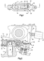
- control system 12 is of the type which is particularly adapted to selectively actuate or deactuate an engine valve and comprises a rocker arm assembly 14 which is shiftable between an active mode wherein it is operable to open the valve, and an inactive mode wherein the valve is not opened; and an actuator assembly 16 which is operable to shift the rocker arm assembly between its active and inactive modes.
- the rocker arm assembly 14 comprises an inner arm assembly 18 which is engageable with the valve actuating cam 20 of the engine, an outer arm 22 which is engageable with a poppet valve 24 which is maintained normally closed by a spring 25 , a biasing spring 26 which acts between the inner and outer arms to bias the inner arm into engagement with the cam 20 and the outer arm into engagement with the plunger 30 of a stationary lash adjuster 32, and a latch member 28 which is slidably received on the outer arm and which is effective to latch the inner and outer arms together to define the active mode of the control system or to unlatch them to define the inactive mode.
- the outer arm 22 is pivotally mounted on the plunger 30 and the inner arm 18 is pivotally mounted on outer arm 22 .
- the construction and the function of the lash adjuster 32 are well known and will not be descried in detail herein.
- the inner arm 18 is preferably a stamped structure which is generally U-shaped in plan, having spaced apart wall sections 34 and 36 , a contact element 38 at the base of the U, and a central spine section 40 .
- the spine section 40 defines the pivot point of the arm in the form of a socket portion 42 which contacts the outer arm as will be described below, and a spring retaining element 44 .
- Aligned bores 46 are formed in the walls 34 and 36 to receive the axle of a needle roller assembly 48 (see FIG. 2).
- the contact element 38 defines a latch surface which interacts with the outer arm 22 and the latch member 28 .
- a pair of outwardly extending stops 50, 51 are formed on the walls 34, 36 to limit relative movement between the inner and outer arms.
- the outer arm 22 is a generally rectangular member in plan view having spaced apart side walls 53 and 54 and converging end portions 56 and 58 , the end portion 56 defining a spring-retaining element 60 , and the end portion 58 defining a valve contacting pad 62 .
- a web element 64 is formed between the walls 52 and 54 and defines a socket portion 66 which is received between the socket portion 42 of the inner arm and the lash adjuster plunger 30 when the arms are assembled.
- the walls 52 and 54 are slotted at 68 and 70 to receive the latch member 28 .
- the inner and outer arms are nested together with the spine section 40 of the inner arm 18 received over the web element 64 of the outer arm 22 .
- the needle roller assembly 48 is received between the walls 34 , 36 of the inner arm with the roller axle having a slip fit within the bores 46 .
- the axle 76 is always in contact with the walls during operation such that no positive retention means such as staking is required to retain the needle roller assembly.
- the socket portion 66 of the outer arm 22 is positioned over the plunger 30 of the lash adjuster 32 , which places the roller assembly 48 of the inner arm 18 in contact with the cam 20 and the contact pad 62 of the outer arm 22 in contact with the valve 24 .
- the spring 26 is positioned over the retainers 44 and 60 between the inner and outer arms, the inner arm 18 is biased into engagement with the cam 20 (via the roller 48 ) and the outer arm 22 is biased into engagement with the valve 24 , the angular position of the rocker arm assembly 14 about the longitudinal axis of the lash adjuster being maintained by the end of the stem of valve 24 being trapped between the walls of the converging end portion 58 of the outer arm 22 .
- the control system 12 is shifted between its active and inactive modes by means of the latch member 28 .
- the latch is in the form of a plate which is mounted on the outer arm 22 and is engageable with the contact element 38 of the inner arm.
- the latch member 28 comprises a flat plate element 78 which slides along the top surface of the outer arm and which has a central region 80 which is engageable with the contact element 38 of the inner arm, and a pair of axially extending finger elements 82 and 84 which straddle the inner arm and are receivable within the slots 68 and 70 of the outer arm.
- the latch member is biased into its latched position and is maintained in position on the outer arm by means of tabs 86 and 88 which partly surround the end 58 of the outer arm.
- the latch member is shown in its active or engaged position with the central region 80 engaged by the inner arm.
- the cam 20 rotates through the broken line position of FIG. 2
- the force of the cam 20 on the roller 48 is transmitted to the outer arm 22 through the latch 28 and to the valve 24 , moving the valve to its open position.
- the latch member 28 is moved to the right as illustrated in FIG. 2 by means of actuator assembly 16 to slide the latch member out of engagement with the inner arm. With the latch disengaged, the force of the cam against the inner arm is not transmitted to the outer arm, and the valve remains in its closed position.
- the actuator assembly is shown somewhat schematically since a variety of linear actuating arrangements can be used to shift the latch member 28 , and the actual arrangement employed will-depend on space and mounting limitations associated with a particular engine in which the system is installed.
- the assembly comprises a bracket member 90 suitably attached to the engine, a solenoid 92 attached to the bracket, an actuating rod 94 which is pivotally mounted to the bracket at 96 and which is slidingly received within the latch member 28 and engaged by the output member 98 of the solenoid, and a compression spring 99 which acts between the solenoid 92 and the rod 94 to bias the latch member into a normally engaged position.
- the rod 96 is received through a spherical socket element formed on the latch member, permitting the latch member to slide along the rod in moving between the valve closed position shown in the full line and the valve open position shown in broken line without undue lash between the actuator and the latch.
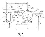
- FIG. 7 is a schematic representation of the valve control system 12 which illustrates how the system overcomes the problems of lash adjuster pump up in the unlatched mode without requiring base circle contact elements and the like.
- Lash adjuster pump up is a major concern for maintaining proper function of the control system. Excessive pump up when the inner arm is engaged with the base circle of the cam 20 will affect both the latching and unlatching functions. In the latched mode pump up will cause the contact element 38 of the inner arm to be loaded against the latch member 28 , not allowing the latch to disengage. In the unlatched mode, pump up will cause the element 28 to be below the latch, not allowing the latch to re-engage.
- a pump up condition occurs when the upward force from the plunger 30 exceeds the downward load from the inner rocker arm at base circle.
- the force from the lash adjuster 32 is the sum of the plunger spring load and the force of the high pressure oil fed to the lash adjuster acting on the plunger projected area, which tries to push the plunger out of the body, the oil pressure being the major contributor.
- This non-equilibrium condition pushes the plunger and outer arm 22 upward, which causes the outer arm to pivot about the valve tip until a static equilibrium is reached. As the outer arm and plunger move axially upward, the inner arm 18 is also pushed upward.
- the cam 20 prevents the roller 48 from moving upward, the inner arm is forced to pivot about the axis of the roller as the plunger moves upward, compressing the spring 26 increasing the load between the inner and outer arms, resulting in either a static condition or until the plunger reaches its travel stop.
- F1 is the force applied by the plunger 30 of the lash adjuster to the rocker arm assembly
- F2 is the force of the spring 26 acting between the inner and outer rocker arms
- F3 is the force of the cam 20 against the roller 48
- F4 is the reaction force against the valve tip
- F5 is the force between the inner and outer arms at the stops 50 and 51
- F6 is the force acting between the inner and outer arms at the plunger contact.
- force F3 applied by the cam 20 to the roller 48 is transmitted from the contact element 38 of the inner arm, through the latch member 28 to the outer arm 22 , and to the valve 24 , opening the valve against the force of the valve spring.
- Shifting of the system from an active to an inactive mode is done when the roller 48 is in contact with the base circle portion of the cam and the forces acting on the latch mechanism are at a minimum.
- the latch member 28 is removed from between the contact element 38 and the outer arm, allowing the inner and outer arms to pivot about each other at the lash adjuster, wherein the force F3 is insufficient to cause valve motion.
- the spring force F2 is calculated to maintain the roller 48 of the inner arm in contact with the cam 20 and the outer arm in contact with the valve 24 , while maintaining sufficient force against the plunger to counteract the plunger force F1 and prevent the lash adjuster from pumping up.
Landscapes
- Engineering & Computer Science (AREA)
- Mechanical Engineering (AREA)
- General Engineering & Computer Science (AREA)
- Valve Device For Special Equipments (AREA)
- Valve-Gear Or Valve Arrangements (AREA)
- Lift Valve (AREA)
Claims (2)
- Ein Ventilsteuersystem (12) für einen Verbrennungsmotor, der einen Zylinderkopf (10), ein Tellerventil (24) und eine Nockenwelle mit einem Nokken (20) darauf geformt aufweist; wobei das Steuersystem Folgendes aufweist: Mittel (30) auf dem Zylinderkopf, die einen Schwenkpunkt definieren; einen ersten Kipp- bzw. Kniearm (22) montiert für eine Drehung um den Schwenkpunkt und in Eingriff bringbar mit dem Tellerventil (24); einen zweiten Kipp- bzw. Kniearm (18) montiert für eine Drehung relativ zum ersten Kipparm (22) und in Eingriff bringbar mit dem Nocken (20); Mittel (26) zum Vorspannen bzw. Beaufschlagen des ersten Kipparms (22) in Eingriff mit dem Schwenkpunkt und des zweiten Kipparms (18) in Eingriff mit dem Nokken (20); und Mittel (16, 28) für ein selektives Verbinden der ersten und zweiten Kipparme für eine gemeinsame Bewegung um den Schwenkpunkt ansprechend auf eine durch den Nocken auf den zweiten Kipparm angelegte Kraft; wobei die Mittel zum Vorspannen des ersten Kipparms in Eingriff mit dem Schwenkpunkt und des zweiten Kipparms in Eingriff mit dem Nocken eine Feder (26) aufweisen, die zwischen den ersten und zweiten Kipparmen wirkt; dadurch gekennzeichnet, dass:
(a) der erste Kipparm (22) ein erstes langgestrecktes Armglied mit einem auf einem Ende davon gebildeten Ventilkontaktierelement (62), einer am entgegengesetzten Ende davon gebildeten, ersten Federaufnahmefläche (56, 60) und einem zwischen dem Ventilkontaktierelement und der Federaufnahmefläche gebildeten, ersten Schwenklagerelement (66) aufweist, und wobei der zweite Kipparm (18) ein zweites langgestrecktes Armglied (34, 36) mit einem an einem Ende davon gebildeten Kontaktelement (38), einer am entgegengesetzten Ende davon gebildeten, zweiten Federaufnahmefläche (44) und ein zwischen dem Kontaktelement (38) und der Federaufnahmefläche (44) gebildetes zweites Schwenklagerelement (42) aufweist, wobei das Kontaktelement (38) benachbart zum Ventilkontaktierelement (62) angeordnet ist und geeignet ist für ein Fixieren bzw. Befestigen relativ dazu durch einen Eingriff mit den Verbindungsmitteln (16, 28). - Vorrichtung nach Anspruch 1, in welcher das Schwenklagerelement eine erste konkave Lageroberfläche (66) und eine konvexe Lageroberfläche definiert, und eine darauf gebildete, zweite konkave Lageroberfläche (42), und ein Nockenkontaktierelement (48) zwischen dem Schwenklagerelement und der Kontaktoberfläche besitzt; wobei das erste Armglied auf den Mitteln aufgenommen wird, die einen Schwenkpunkt (P) definieren, und zwar mit der ersten konkaven Lageroberfläche (66) in Kontakt mit dem Schwenkpunkt, und wobei das zweite Armglied (18) auf dem ersten Armglied (22) aufgenommen ist, und zwar mit der zweiten konkaven Lageroberfläche (42) in Eingriff mit der konvexen Lageroberfläche; wobei die zwischen den ersten und zweiten Kipparmen (18, 22) wirkende Feder (26) eine Kompressionsfeder aufweist, die zwischen den ersten und zweiten Federaufnahmeflächen (44, 60) aufgenommen ist.
Applications Claiming Priority (2)
| Application Number | Priority Date | Filing Date | Title |
|---|---|---|---|
| US412474 | 1995-03-28 | ||
| US08/412,474 US5660153A (en) | 1995-03-28 | 1995-03-28 | Valve control system |
Publications (2)
| Publication Number | Publication Date |
|---|---|
| EP0735249A1 EP0735249A1 (de) | 1996-10-02 |
| EP0735249B1 true EP0735249B1 (de) | 2001-08-01 |
Family
ID=23633146
Family Applications (1)
| Application Number | Title | Priority Date | Filing Date |
|---|---|---|---|
| EP96301979A Expired - Lifetime EP0735249B1 (de) | 1995-03-28 | 1996-03-22 | Ventilsteuervorrichtung |
Country Status (6)
| Country | Link |
|---|---|
| US (1) | US5660153A (de) |
| EP (1) | EP0735249B1 (de) |
| JP (1) | JP3830197B2 (de) |
| KR (1) | KR100306982B1 (de) |
| CN (1) | CN1087390C (de) |
| DE (1) | DE69614166T2 (de) |
Families Citing this family (64)
| Publication number | Priority date | Publication date | Assignee | Title |
|---|---|---|---|---|
| US5584267A (en) * | 1995-12-20 | 1996-12-17 | Eaton Corporation | Latchable rocker arm mounting |
| US5653198A (en) * | 1996-01-16 | 1997-08-05 | Ford Motor Company | Finger follower rocker arm system |
| US5908015A (en) * | 1996-07-06 | 1999-06-01 | Meta Motoren- Und Energie Technik Gmbh | Arrangement for interrupting the flow of force between a camshaft and a valve |
| US6092497A (en) * | 1997-10-30 | 2000-07-25 | Eaton Corporation | Electromechanical latching rocker arm valve deactivator |
| US5964193A (en) * | 1998-08-20 | 1999-10-12 | Ford Global Technologies, Inc. | Synchronous hydraulic lash adjuster |
| US5967105A (en) * | 1998-08-24 | 1999-10-19 | Ford Global Technologies, Inc. | Hydraulic lash adjuster with an open ended top plunger surface |
| US5931132A (en) * | 1998-08-24 | 1999-08-03 | Freeland; Mark | Hydraulic lash adjuster with pressure relief check valve |
| US6006710A (en) * | 1998-08-31 | 1999-12-28 | Ford Global Technologies, Inc. | Hydraulic lash adjuster mechanism with pressure controlled leak down |
| US6497207B2 (en) | 2000-10-20 | 2002-12-24 | Delphi Technologies, Inc. | Deactivation roller hydraulic valve lifter |
| US7263956B2 (en) | 1999-07-01 | 2007-09-04 | Delphi Technologies, Inc. | Valve lifter assembly for selectively deactivating a cylinder |
| US6418904B2 (en) | 2000-04-03 | 2002-07-16 | Daimlerchrysler Corporation | Pulse drive valve deactivator |
| DE10038917A1 (de) | 2000-08-09 | 2002-02-21 | Fev Motorentech Gmbh | Kolbenbrennkraftmaschine mit deaktivierbaren, mechanisch betätigbaren Gaswechselventilen |
| US6314928B1 (en) * | 2000-12-06 | 2001-11-13 | Ford Global Technologies, Inc. | Rocker arm assembly |
| US6318318B1 (en) * | 2001-05-15 | 2001-11-20 | Ford Global Technologies, Inc. | Rocker arm assembly |
| EP1267043A1 (de) * | 2001-06-15 | 2002-12-18 | EATON AUTOMOTIVE S.p.A. | Ventilbetätigungsanordnung einer Brennkraftmaschine |
| DE10146129A1 (de) | 2001-09-19 | 2003-04-03 | Ina Schaeffler Kg | Schaltelement für einen Ventiltrieb einer Brennkraftmaschine |
| DE10155800A1 (de) * | 2001-11-14 | 2003-05-22 | Ina Schaeffler Kg | Schlepphebel eines Ventiltriebs einer Brennkraftmaschine |
| DE10155801A1 (de) * | 2001-11-14 | 2003-05-22 | Ina Schaeffler Kg | Schlepphebel eines Ventiltriebs einer Brennkraftmaschine |
| ATE300665T1 (de) * | 2002-02-06 | 2005-08-15 | Ina Schaeffler Kg | Schaltelement für einen ventiltrieb einer brennkraftmaschine |
| US7273026B2 (en) | 2002-10-18 | 2007-09-25 | Maclean-Fogg Company | Roller follower body |
| US6871622B2 (en) | 2002-10-18 | 2005-03-29 | Maclean-Fogg Company | Leakdown plunger |
| US7028654B2 (en) | 2002-10-18 | 2006-04-18 | The Maclean-Fogg Company | Metering socket |
| US7128034B2 (en) | 2002-10-18 | 2006-10-31 | Maclean-Fogg Company | Valve lifter body |
| US7191745B2 (en) | 2002-10-18 | 2007-03-20 | Maclean-Fogg Company | Valve operating assembly |
| US6837197B2 (en) * | 2003-03-19 | 2005-01-04 | Eaton Corporation | Dual valve lift and valve deactivation |
| US20040244751A1 (en) * | 2003-06-03 | 2004-12-09 | Falkowski Alan G. | Deactivating valve lifter |
| US7040265B2 (en) * | 2003-06-03 | 2006-05-09 | Daimlerchrysler Corporation | Multiple displacement system for an engine |
| DE10330882A1 (de) * | 2003-07-09 | 2005-01-27 | Ina-Schaeffler Kg | Verfahren zur Herstellung eines Außenhebels eines schaltbaren Schlepphebels |
| DE102005037052B4 (de) * | 2005-08-05 | 2017-06-22 | Schaeffler Technologies AG & Co. KG | Schaltbarer Schlepphebel eines Ventiltriebs einer Brennkraftmaschine |
| DE102005037051A1 (de) * | 2005-08-05 | 2007-02-08 | Schaeffler Kg | Schaltbarer Schlepphebel eines Ventiltriebs einer Brennkraftmaschine |
| DE102005048984A1 (de) * | 2005-10-13 | 2007-04-19 | Schaeffler Kg | Schaltbarer Schlepphebel |
| CN100547230C (zh) * | 2006-08-15 | 2009-10-07 | 财团法人工业技术研究院 | 阀门控制机构 |
| CN101550848B (zh) * | 2006-08-15 | 2012-02-29 | 财团法人工业技术研究院 | 阀门控制机构 |
| DE102007021856A1 (de) | 2007-05-10 | 2008-11-13 | Schaeffler Kg | Schaltbarer Schlepphebel eines Ventiltriebs einer Brennkraftmaschine |
| DE102008057830A1 (de) * | 2007-11-21 | 2009-05-28 | Schaeffler Kg | Abschaltbarer Stößel |
| US8210144B2 (en) * | 2008-05-21 | 2012-07-03 | Caterpillar Inc. | Valve bridge having a centrally positioned hydraulic lash adjuster |
| US9581058B2 (en) | 2010-08-13 | 2017-02-28 | Eaton Corporation | Development of a switching roller finger follower for cylinder deactivation in internal combustion engines |
| US8985074B2 (en) | 2010-03-19 | 2015-03-24 | Eaton Corporation | Sensing and control of a variable valve actuation system |
| US9267396B2 (en) | 2010-03-19 | 2016-02-23 | Eaton Corporation | Rocker arm assembly and components therefor |
| US9291075B2 (en) | 2008-07-22 | 2016-03-22 | Eaton Corporation | System to diagnose variable valve actuation malfunctions by monitoring fluid pressure in a control gallery |
| WO2015134466A1 (en) | 2014-03-03 | 2015-09-11 | Eaton Corporation | Valve actuating device and method of making same |
| US9938865B2 (en) | 2008-07-22 | 2018-04-10 | Eaton Corporation | Development of a switching roller finger follower for cylinder deactivation in internal combustion engines |
| US9038586B2 (en) | 2010-03-19 | 2015-05-26 | Eaton Corporation | Rocker assembly having improved durability |
| US10415439B2 (en) | 2008-07-22 | 2019-09-17 | Eaton Intelligent Power Limited | Development of a switching roller finger follower for cylinder deactivation in internal combustion engines |
| US9016252B2 (en) | 2008-07-22 | 2015-04-28 | Eaton Corporation | System to diagnose variable valve actuation malfunctions by monitoring fluid pressure in a hydraulic lash adjuster gallery |
| US9284859B2 (en) | 2010-03-19 | 2016-03-15 | Eaton Corporation | Systems, methods, and devices for valve stem position sensing |
| MX2011000898A (es) * | 2008-07-22 | 2011-03-15 | Eaton Corp | Sistema de control de aceite de tren de valvulas y valvula de control de aceite. |
| US9228454B2 (en) | 2010-03-19 | 2016-01-05 | Eaton Coporation | Systems, methods and devices for rocker arm position sensing |
| US20190309663A9 (en) | 2008-07-22 | 2019-10-10 | Eaton Corporation | Development of a switching roller finger follower for cylinder deactivation in internal combustion engines |
| US10087790B2 (en) | 2009-07-22 | 2018-10-02 | Eaton Corporation | Cylinder head arrangement for variable valve actuation rocker arm assemblies |
| US11181013B2 (en) | 2009-07-22 | 2021-11-23 | Eaton Intelligent Power Limited | Cylinder head arrangement for variable valve actuation rocker arm assemblies |
| US9194261B2 (en) | 2011-03-18 | 2015-11-24 | Eaton Corporation | Custom VVA rocker arms for left hand and right hand orientations |
| US8196556B2 (en) * | 2009-09-17 | 2012-06-12 | Delphi Technologies, Inc. | Apparatus and method for setting mechanical lash in a valve-deactivating hydraulic lash adjuster |
| US9874122B2 (en) | 2010-03-19 | 2018-01-23 | Eaton Corporation | Rocker assembly having improved durability |
| US9885258B2 (en) | 2010-03-19 | 2018-02-06 | Eaton Corporation | Latch interface for a valve actuating device |
| EP2734715B1 (de) * | 2011-07-22 | 2015-05-06 | Volvo Lastvagnar AB | Ventilbetätigungsmechanismus und kraftfahrzeug mit einem solchen ventilbetätigungsmechanismus |
| EP2653673A1 (de) | 2012-04-19 | 2013-10-23 | Eaton S.r.l. | Schaltbarer Kipphebel |
| US9650921B2 (en) * | 2013-01-31 | 2017-05-16 | Eaton Corporation | Centrifugal process to eliminate air in high pressure chamber of hydraulic lash adjuster |
| USD750670S1 (en) | 2013-02-22 | 2016-03-01 | Eaton Corporation | Rocker arm |
| GB201703798D0 (en) * | 2017-03-09 | 2017-04-26 | Eaton Srl | Actuation arrangement for actuating a latch in a switchable rocker arm and a valve train comprising the same |
| GB201712662D0 (en) | 2017-08-07 | 2017-09-20 | Eaton Srl | Actuation apparatus |
| JP7004152B2 (ja) * | 2018-01-12 | 2022-01-21 | トヨタ自動車株式会社 | 動弁機構 |
| JP6969395B2 (ja) * | 2018-01-17 | 2021-11-24 | トヨタ自動車株式会社 | ロッカアーム |
| DE102018120270A1 (de) * | 2018-08-21 | 2020-02-27 | Schaeffler Technologies AG & Co. KG | Variabler Ventiltrieb für Hubkolbenbrennkraftmaschinen |
Citations (1)
| Publication number | Priority date | Publication date | Assignee | Title |
|---|---|---|---|---|
| US5544626A (en) * | 1995-03-09 | 1996-08-13 | Ford Motor Company | Finger follower rocker arm with engine valve deactivator |
Family Cites Families (11)
| Publication number | Priority date | Publication date | Assignee | Title |
|---|---|---|---|---|
| DE2753197A1 (de) * | 1976-12-15 | 1978-06-22 | Eaton Corp | Ventilsteuervorrichtung |
| US4203397A (en) * | 1978-06-14 | 1980-05-20 | Eaton Corporation | Engine valve control mechanism |
| US4556025A (en) * | 1983-11-18 | 1985-12-03 | Mazda Motor Corporation | Engine valve mechanism having valve disabling device |
| US4607600A (en) * | 1984-12-25 | 1986-08-26 | Toyota Jidosha Kabushiki Kaisha | Valve actuating apparatus in internal combustion engine |
| DE3613945A1 (de) * | 1985-04-26 | 1986-10-30 | Mazda Motor Corp., Hiroshima | Veraenderbarer ventilmechanismus fuer verbrennungsmaschinen |
| US4768467A (en) * | 1986-01-23 | 1988-09-06 | Fuji Jukogyo Kabushiki Kaisha | Valve operating system for an automotive engine |
| DE3800347A1 (de) * | 1987-01-08 | 1988-09-29 | Honda Motor Co Ltd | Ventilbetaetigungsvorrichtung in einer brennkraftmaschine |
| JP3200131B2 (ja) * | 1991-10-23 | 2001-08-20 | 株式会社ユニシアジェックス | エンジンの弁作動装置 |
| DE4136143A1 (de) * | 1991-11-02 | 1993-05-06 | Audi Ag, 8070 Ingolstadt, De | Ventilsteuereinrichtung fuer eine brennkraftmaschine |
| US5239952A (en) * | 1991-11-08 | 1993-08-31 | Atsugi Unisia Corporation | Valve actuating apparatus |
| DE4317638C1 (de) * | 1993-05-27 | 1994-08-18 | Audi Ag | Ventilbetätigungsvorrichtung für eine Mehrzylinder-Brennkraftmaschine |
-
1995
- 1995-03-28 US US08/412,474 patent/US5660153A/en not_active Expired - Fee Related
-
1996
- 1996-03-22 EP EP96301979A patent/EP0735249B1/de not_active Expired - Lifetime
- 1996-03-22 DE DE69614166T patent/DE69614166T2/de not_active Expired - Lifetime
- 1996-03-28 CN CN96108049A patent/CN1087390C/zh not_active Expired - Lifetime
- 1996-03-28 KR KR1019960008847A patent/KR100306982B1/ko not_active Expired - Lifetime
- 1996-03-28 JP JP7347396A patent/JP3830197B2/ja not_active Expired - Lifetime
Patent Citations (1)
| Publication number | Priority date | Publication date | Assignee | Title |
|---|---|---|---|---|
| US5544626A (en) * | 1995-03-09 | 1996-08-13 | Ford Motor Company | Finger follower rocker arm with engine valve deactivator |
Also Published As
| Publication number | Publication date |
|---|---|
| CN1150618A (zh) | 1997-05-28 |
| DE69614166D1 (de) | 2001-09-06 |
| CN1087390C (zh) | 2002-07-10 |
| EP0735249A1 (de) | 1996-10-02 |
| KR100306982B1 (ko) | 2002-04-06 |
| JPH0921306A (ja) | 1997-01-21 |
| DE69614166T2 (de) | 2002-04-25 |
| KR960034666A (ko) | 1996-10-24 |
| JP3830197B2 (ja) | 2006-10-04 |
| US5660153A (en) | 1997-08-26 |
Similar Documents
| Publication | Publication Date | Title |
|---|---|---|
| EP0735249B1 (de) | Ventilsteuervorrichtung | |
| US5529033A (en) | Multiple rocker arm valve control system | |
| EP0821142B1 (de) | Zweiphasen Ventilsteuerungseinrichtung | |
| US5524580A (en) | Adjusting mechanism for a valve control system | |
| US5544626A (en) | Finger follower rocker arm with engine valve deactivator | |
| EP0860588B1 (de) | Auf zwei unterschiedliche Ventilhübe schaltbare Ventilbetätigungsvorrichtung | |
| US6615782B1 (en) | Two-step finger follower rocker arm | |
| EP1367228B1 (de) | Kipphebel zur zweistufigen Nockenbetätigung | |
| US5619958A (en) | Engine valve control system using a latchable rocker arm | |
| US6668775B2 (en) | Lock-pin cartridge for a two-step finger follower rocker arm | |
| US7305951B2 (en) | Two-step roller finger follower | |
| JP4541733B2 (ja) | 2段弁リフトと弁の作動停止 | |
| EP0781900B1 (de) | Verriegelbare Schwinghebel-Abstützanordnung | |
| CN101365865B (zh) | 带有停阀摇臂的气门控制系统 | |
| EP0814239A1 (de) | Verriegelungsvorrichtung für ein Ventilsteuersystem | |
| US20180023425A1 (en) | Coupling pin anti-rotation for a switchable roller finger follower | |
| EP3455469B1 (de) | Schlepphebel | |
| MXPA96001186A (en) | Valv control system |
Legal Events
| Date | Code | Title | Description |
|---|---|---|---|
| PUAI | Public reference made under article 153(3) epc to a published international application that has entered the european phase |
Free format text: ORIGINAL CODE: 0009012 |
|
| AK | Designated contracting states |
Kind code of ref document: A1 Designated state(s): DE FR GB IT |
|
| 17P | Request for examination filed |
Effective date: 19970322 |
|
| 17Q | First examination report despatched |
Effective date: 19990316 |
|
| GRAG | Despatch of communication of intention to grant |
Free format text: ORIGINAL CODE: EPIDOS AGRA |
|
| GRAG | Despatch of communication of intention to grant |
Free format text: ORIGINAL CODE: EPIDOS AGRA |
|
| GRAH | Despatch of communication of intention to grant a patent |
Free format text: ORIGINAL CODE: EPIDOS IGRA |
|
| GRAH | Despatch of communication of intention to grant a patent |
Free format text: ORIGINAL CODE: EPIDOS IGRA |
|
| GRAH | Despatch of communication of intention to grant a patent |
Free format text: ORIGINAL CODE: EPIDOS IGRA |
|
| GRAH | Despatch of communication of intention to grant a patent |
Free format text: ORIGINAL CODE: EPIDOS IGRA |
|
| GRAA | (expected) grant |
Free format text: ORIGINAL CODE: 0009210 |
|
| AK | Designated contracting states |
Kind code of ref document: B1 Designated state(s): DE FR GB IT |
|
| REF | Corresponds to: |
Ref document number: 69614166 Country of ref document: DE Date of ref document: 20010906 |
|
| ITF | It: translation for a ep patent filed | ||
| ET | Fr: translation filed | ||
| REG | Reference to a national code |
Ref country code: GB Ref legal event code: IF02 |
|
| PLBE | No opposition filed within time limit |
Free format text: ORIGINAL CODE: 0009261 |
|
| STAA | Information on the status of an ep patent application or granted ep patent |
Free format text: STATUS: NO OPPOSITION FILED WITHIN TIME LIMIT |
|
| 26N | No opposition filed | ||
| REG | Reference to a national code |
Ref country code: FR Ref legal event code: PLFP Year of fee payment: 20 |
|
| PGFP | Annual fee paid to national office [announced via postgrant information from national office to epo] |
Ref country code: IT Payment date: 20150316 Year of fee payment: 20 |
|
| PGFP | Annual fee paid to national office [announced via postgrant information from national office to epo] |
Ref country code: FR Payment date: 20150224 Year of fee payment: 20 Ref country code: GB Payment date: 20150224 Year of fee payment: 20 |
|
| PGFP | Annual fee paid to national office [announced via postgrant information from national office to epo] |
Ref country code: DE Payment date: 20150331 Year of fee payment: 20 |
|
| REG | Reference to a national code |
Ref country code: DE Ref legal event code: R071 Ref document number: 69614166 Country of ref document: DE |
|
| REG | Reference to a national code |
Ref country code: GB Ref legal event code: PE20 Expiry date: 20160321 |
|
| PG25 | Lapsed in a contracting state [announced via postgrant information from national office to epo] |
Ref country code: GB Free format text: LAPSE BECAUSE OF EXPIRATION OF PROTECTION Effective date: 20160321 |