EP0735290B1 - Tellerfeder-Kupplungsvorrichtung für Kraftfahrzeuge - Google Patents
Tellerfeder-Kupplungsvorrichtung für Kraftfahrzeuge Download PDFInfo
- Publication number
- EP0735290B1 EP0735290B1 EP96400648A EP96400648A EP0735290B1 EP 0735290 B1 EP0735290 B1 EP 0735290B1 EP 96400648 A EP96400648 A EP 96400648A EP 96400648 A EP96400648 A EP 96400648A EP 0735290 B1 EP0735290 B1 EP 0735290B1
- Authority
- EP
- European Patent Office
- Prior art keywords
- diaphragm
- assembly
- cover plate
- cover
- flank
- Prior art date
- Legal status (The legal status is an assumption and is not a legal conclusion. Google has not performed a legal analysis and makes no representation as to the accuracy of the status listed.)
- Expired - Lifetime
Links
- 230000007246 mechanism Effects 0.000 title claims description 17
- 230000009471 action Effects 0.000 claims description 5
- 230000002093 peripheral effect Effects 0.000 claims description 4
- 230000003313 weakening effect Effects 0.000 claims 2
- 241000826860 Trapezium Species 0.000 claims 1
- 238000006243 chemical reaction Methods 0.000 description 7
- 230000000740 bleeding effect Effects 0.000 description 3
- 230000008878 coupling Effects 0.000 description 3
- 238000010168 coupling process Methods 0.000 description 3
- 238000005859 coupling reaction Methods 0.000 description 3
- 239000000463 material Substances 0.000 description 3
- 239000002184 metal Substances 0.000 description 3
- 210000002105 tongue Anatomy 0.000 description 3
- 230000009467 reduction Effects 0.000 description 2
- 230000015572 biosynthetic process Effects 0.000 description 1
- 230000037431 insertion Effects 0.000 description 1
- 238000003780 insertion Methods 0.000 description 1
- 230000036316 preload Effects 0.000 description 1
Images

Classifications
-
- F—MECHANICAL ENGINEERING; LIGHTING; HEATING; WEAPONS; BLASTING
- F16—ENGINEERING ELEMENTS AND UNITS; GENERAL MEASURES FOR PRODUCING AND MAINTAINING EFFECTIVE FUNCTIONING OF MACHINES OR INSTALLATIONS; THERMAL INSULATION IN GENERAL
- F16D—COUPLINGS FOR TRANSMITTING ROTATION; CLUTCHES; BRAKES
- F16D13/00—Friction clutches
-
- F—MECHANICAL ENGINEERING; LIGHTING; HEATING; WEAPONS; BLASTING
- F16—ENGINEERING ELEMENTS AND UNITS; GENERAL MEASURES FOR PRODUCING AND MAINTAINING EFFECTIVE FUNCTIONING OF MACHINES OR INSTALLATIONS; THERMAL INSULATION IN GENERAL
- F16D—COUPLINGS FOR TRANSMITTING ROTATION; CLUTCHES; BRAKES
- F16D13/00—Friction clutches
- F16D13/58—Details
- F16D13/583—Diaphragm-springs, e.g. Belleville
- F16D13/585—Arrangements or details relating to the mounting or support of the diaphragm on the clutch on the clutch cover or the pressure plate
Definitions
- the present invention relates generally to diaphragm clutch mechanisms, especially for vehicles automobile, of the type comprising a cover, at least one tray, said pressure plate, intended to be secured in rotation with the cover being mounted movable axially relative to the latter, a diaphragm, comprising a peripheral part forming Belleville washer, for action on the pressure plate, and a central part fragmented into radial fingers, for action of a clutch release bearing, and assembly means subjecting pivot the diaphragm to the cover by applying axially said diaphragm, with an elastic clamping load, against a primary support carried by the cover, said means assembly comprising, on the one hand, assembly tabs coupled to the cover and having an axial part passing through the diaphragm with enlarged openings between the fingers radials of it as well as an end wing, folded in favor of a groove, which presents the axial part, and defining with said axial part a wedging elbow and, on the other hand, at least a crown, called a crown ring
- Such a clutch mechanism is adapted to be added by its cover on a tray, called reaction tray, secured to a first tree, usually a leading tree, with insertion between the reaction plate and the pressure plate of a disc of friction in rotation with a second shaft, generally a driven tree, while, around it, is a room, said clutch release bearing, capable of acting on the radial fingers of the diaphragm, for control in release of the clutch thus formed, who is normally engaged; the pressure plate in such position pressing the friction disc against the reaction plate under the stress of the peripheral part forming a washer Belleville diaphragm leaning on the primary support.
- the object of the present invention is to respond to this wish and therefore to create a device that allows better control of the axial clamping load exerted by the crown ring on the diaphragm while using an economical solution.
- a mechanism of the above-mentioned type is characterized in that the groove has a trapezoidal shape asymmetrical with a flat bottom between two lateral sides inclined and having different inclination values, the side closer to the free end of the assembly tabs being more tilted than the other side closest to the cover.
- This arrangement allows the end to be folded if necessary free legs at an angle less than or greater than 90 °.
- one of the sides may have an inclination of 62.30 ° and the other side an inclination of 77.30 °.
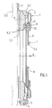
- a clutch mechanism for motor vehicle of the kind comprising successively axially at minus a pressure plate 5, a diaphragm 6 of frustoconical shape in the free state and a metal cover 1, here in stamped sheet metal.
- This mechanism forms a unitary sub-assembly and is adapted to be fixed via its cover 1 on a steering wheel 50 (shown schematically in Figure 1), possibly divided, stalled in rotation on a driving shaft, here the engine crankshaft of the vehicle.
- a steering wheel 50 shown schematically in Figure 1
- a driving shaft here the engine crankshaft of the vehicle.
- the diaphragm 6 is supported on the cover 1 for action on reaction plate 5 and tightening of friction linings a friction disc 51 between the flywheel 50, forming a plate reaction, and the pressure plate 5.
- the clutch is therefore normally engaged, the engine torque being transmitted from the tree leading to a led tree, here the input tree of the gearbox, through the friction disc 51 comprising an internally fluted hub (not visible) for its connection in rotation to said driven shaft.
- This friction disc 51 which is not part of the invention does not will not be described in more detail here. However, for the record, will recall that this disc 51 has a support disc bearing fixing on its outer periphery, on each of its faces, friction linings 52.
- This support disc is coupled to the hub mentioned above either rigidly, for example by riveting on a hub flange, either resiliently through elastic members mounted in housings facing each other respectively in a rotating wedge, possibly after adjusting the angular play, on the hub and in guide washers arranged axially on either side of the sail and secured to the support disc.
- stop 54 acts by pushing on the internal end of the fingers 8 of the diaphragm 6 pivotally mounted on the cover 1, as described below.
- Coupling means 4 intervene between the cover 1 and the pressure plate 5 for rotational connection, with mobility axial, of the pressure plate 5 with the cover 1.
- annular cover 1 has here a shape of deep plate with a bottom perforated centrally and connected, by through a generally oriented annular skirt axial, to a fixing flange.
- This cover 1 is here in sheet metal stamped.
- the rim and the bottom are generally oriented transverse, the bottom extending radially towards the axis of the whole, while the rim extends in a direction opposite to the axis of the assembly.
- the coupling means 4 here consist of tongues elastic 4 tangential orientation.
- the fixing flange presents a first series of coplanar areas 2, provided with holes for passage of fixing, such as screws, of the clutch mechanism to the steering wheel 50 and a second series of coplanar areas 3, axially offset and circumferentially in alternation with respect to the first series 2.
- the tongues 4 are each fixed at one of their ends, here by riveting, to the second series of tracks 3 and to their other end with a radial orientation leg, which the plate presents pressure 5 projecting from its outer periphery ( Figure 1).
- the tabs 4 are distributed circularly, their number depending applications. Here three sets of tabs 4, possibly superimposed, are provided.
- the skirt of the cover 1 here surrounds the friction disc 50, the pressure plate 5 and diaphragm 6, the veil 50 being of flat shape.
- flywheel 50 can be provided at its periphery with a axially oriented annular skirt surrounding the linings of friction 52 of friction disc 51, so that the depth of the cover 1 depends on the applications, in particular on the steering wheel configuration.
- the tabs 4 recall the pressure plate 5 towards the bottom of the cover 1, which frees the friction linings 52 of the friction disc 51 during the disengagement maneuver of the clutch.
- the tongues 4 can extend radially.
- the coupling means 4 may consist of lugs pressure plate radials 5 engaged in openings the skirt of the cover 1 for forming a tenon-mortise type connection.
- the diaphragm 6 has a peripheral part 7 of the type Belleville washer and a central part fragmented into fingers radial 8 by slots 9 opening internally into the central aperture of the diaphragm and externally in enlarged orifices 10 made at the internal periphery of the washer Belleville 7.
- the outer periphery of the Belleville washer 7 of the diaphragm 6 takes support on an annular boss 53, here fragmented, of the plate pressure 5, while at its internal periphery, the washer Belleville 7 of diaphragm 6 is inserted between a primary support 11 carried by the cover (the bottom thereof) and a support secondary 17 (arranged opposite the primary support) carried by assembly tabs 12 coupled to the cover 1 (at the bottom thereof).
- the primary support 11 is formed by stamping and has a rounded cord shape.
- the secondary support 17 is formed at the periphery external of a support washer 13, called a crown ring, carried by assembly lugs 12 axially oriented.
- These legs 12 through an axial part 14 the enlarged orifices 10 of the diaphragm 6 and come here in one piece from the bottom of the cover 1 by cutting and folding.
- These legs 12 are flat and thin, i.e. they have a rectangular shape in section being circumferentially of higher dimension and transversely of smaller dimension. Legs 12 are here thin radially and elongated circumferentially.
- These legs 12 are intended for their free end 15, the furthest from the bottom of cover 1, to be folded radially outwards to formation of a setting bend and axial setting of the crown ring 13, here of frustoconical shape, with an edge at its outer periphery rounded 21, for forming the secondary support 17.
- This crown 13 is entirely disposed radially beyond assembly tabs 12.
- each axial part 14 is affected by a groove 16 materializing the folding line and making it easier.
- This groove 16 has in section a trapezoidal shape with a flat bottom 19 and two inclined lateral sides. It reduces locally the thickness of the tab 12.
- the tabs 12 apply a pretension to the crown 13 a value for example greater than that of the diaphragm 6 at the level of the clutch release bearing 54 at the internal end of the fingers 8.
- the diaphragm 6 is constantly supported on its primary support 11 with elastic clamping of the diaphragm between its primary support 11, in the form of a half-wave, and secondary support 17.
- the crown ring 13 presents its internal periphery two internal edges 23,22 respectively in contact with the folded wing 15 and the axial part 14 of the legs 14.
- the shape of the groove is therefore very important for folding legs and determining the elastic tightening of the diaphragm 6.
- the invention proposes to make the groove 16 of asymmetrical shape trapezoidal.
- Such a groove 16 transversely affects the legs of assembly 12 over their entire width and is here open in direction opposite to the axis of the assembly which locally reduces it thickness.
- This groove has a section in the shape of a trapezoid having a flat bottom 19 between two inclined lateral sides 30.31.
- These sides have values of different inclination, the side 31 closest to the end free 15 (the end wing 15) of the assembly lugs 12 being more inclined than the other side 30 closest to the cover 1, more precisely from the bottom of it.
- the inclination value of the flank 31 is greater than 10% that of the inclination of the other flank 30.
- the depth of the groove is between 0.15 and 0.30e, e being the thickness of an assembly tab 12.
- This folding is done generally at an angle of 90 °. Well heard this angle may be less than or greater than 90 ° depending on the applications.
- This folding makes it possible to tilt the crown 13 more or less frustoconical shape and therefore to modify the load exerted by the crown ring 13 on the diaphragm 6, thus tightened elastically between its elastic secondary support 17 and its primary support 11 rigid.
- the diaphragm 6 can be kept permanently against its primary support 11.
- the diaphragm 6 pivots satisfactorily between its supports 17.11 with reduction of hysteresis phenomena (and therefore friction), the secondary support 17 deviating to take account of the variation in thickness of the diaphragm 6 due to the inclination of this one.
- the asymmetrical bleeding favors the movement of the crown 13 which is thus less embedded in the wedging elbow 14.15.
- the load exerted by the crown ring 13 may be greater than the load exerted by the clutch release bearing 54 on the fingers 8 of the diaphragm 6 at the start of the disengagement operation of the clutch and then become less than said load exerted by the clutch release bearing 54 and possibly at the end of operation of disengagement again become greater than this as described in the document US-A-4,4326,611.
- a clearance may exist between the primary supports 11 and secondary 17.
- the asymmetrical bleeding 16 makes it possible to reduce the friction of the diaphragm 6 between its primary supports 11 and secondary 17.
- the present invention is not limited to the example described.
- the internal section of the crown ring 13 can be rounded with reduction of phenomena of incrustation of the crown 13 in the axial part 14 legs 12.
- the assembly lugs 12 can belong to a part comb-shaped annular through the bottom of the cover 1 in being in abutment on the face of said bottom turned away from the diaphragm 6.
- staples can be used as in Figure 7 of the document US-A-4,326,611, said staples passing through the bottom of the cover 1 and diaphragm 6 to present two end wings folded in opposite direction to the axis of the assembly respectively in contact with the crown ring and the cover.
- the assembly tabs 12 are therefore carried by the cover in being harnessed to it.
- the crown ring 13 may have the shape of a V at its periphery external (the point of V forming the secondary support) and be radial orientation at its inner periphery as in Figure 7 of the document US-A-4,326,611.
- the legs 12 may be circumferentially thin and be radially elongated. This is made possible because usually the orifices 10 are of generally rectangular shape.
- the legs pass through windows made in the crown ring 13, on the internal periphery thereof and the grooves 16 extend radially.
- the rigid primary support 11 can be formed by a mounted rod in a groove in the bottom of the cover.
- the scope of the invention also extends to the case where the clutch mechanism is mounted on the reaction plate, the clutch mechanism - reaction plate assembly form a clutch module added later on the engine crankshaft.
- a support crown can be inserted between the crown ring and the folded end 15 of the legs 12.
- the support crown collects the efforts of folding of the legs 12 while being higher than the folded end 15 legs 12. A play may then exist between the primary supports 11 and secondary 17.
- the angle of inclination between the two sides is greater than 90 °, preferably greater than 100 °.
- the difference inclination between the sides 30.31 allows for a given angle between the two sides to keep a maximum of material between the side 30 and the rooting area of the legs 12 to the cover. We gets 12 stronger legs.
- the legs 12 can extend axially in the opposite direction to the pressure 5, which in this case passes through the cover through bosses 1.
Landscapes
- Engineering & Computer Science (AREA)
- General Engineering & Computer Science (AREA)
- Mechanical Engineering (AREA)
- Mechanical Operated Clutches (AREA)
Claims (4)
- Membranfeder-Kupplungsmechanismus, insbesondere für Kraftfahrzeuge, umfassend einen Deckel (1), wenigstens eine als Druckplatte (5) bezeichnete Platte, die für die drehfeste Verbindung mit dem Deckel (1) bestimmt und im Verhältnis zu diesem axial beweglich gelagert ist, eine Membranfeder (6) mit einem eine Tellerfeder (7) bildenden Umfangsteil zur Einwirkung auf die Druckplatte und einem in radiale Finger (8) unterteilten Mittelteil für die Einwirkung eines Ausrücklagers (54) sowie Mittel zur schwenkbaren Befestigung der Membranfeder (6) mit einer elastischen Einspannkraft an einer am Deckel (1) angebrachten Primärauflage (11), wobei die besagten Verbindungsmittel einerseits Verbindungsansätze (12) umfassen, die an den Deckel (1) angefügt sind und einen axialen Teil (14), der durch die Membranfeder (6) durch erweiterte Öffnungen (10) hindurchgeht, die zwischen deren radialen Fingern (8) angeordnet sind, sowie einen Abschlußschenkel (15) enthalten, der mittels eines Einschnitts (16), den der axiale Teil (14) aufweist, gebogen ist und zusammen mit dem besagten axialen Teil (14) einen Sicherungsbogen definiert, und andererseits einen Ringkranz (13) umfassen, der in dem besagten Sicherungsbogen gesichert ist und für die Membranfeder (6) eine Sekundärauflage (17) bildet, die in etwa gegenüber der Primärauflage (11) angeordnet ist, wobei der Einschnitt (16) ein trapezförmiges Profil mit einem flachen Boden (19) zwischen zwei geneigten Seitenflanken (30, 31) aufweist ,
dadurch gekennzeichnet,
daß die geneigten Seitenflanken (30, 31) unterschiedliche Neigungswerte haben, wobei die dem Abschlußschenkel (15) der Verbindungsansätze (12) am nächsten liegende Flanke (31) stärker als die dem Deckel (1) am nächsten liegende andere Flanke (30) geneigt ist. - Mechanismus nach Anspruch 1, dadurch gekennzeichnet, daß die am stärksten geneigte Flanke (31) einen Neigungswert hat, der größer als 10% des Neigungswerts der anderen Flanke (30) ist.
- Mechanismus nach Anspruch 1 oder 2, dadurch gekennzeichnet, daß der Neigungswinkel zwischen den beiden geneigten Flanken größer als 100° ist.
- Mechanismus nach einem der Ansprüche 1 bis 3, dadurch gekennzeichnet, daß die Verbindungsansätze (12) radial dünn und umfangsmäßig langgestreckt sind und daß die besagten Verbindungsansätze (12) einstückig mit dem Deckel ausgeführt sind.
Applications Claiming Priority (2)
| Application Number | Priority Date | Filing Date | Title |
|---|---|---|---|
| FR9504000 | 1995-03-30 | ||
| FR9504000A FR2732423B1 (fr) | 1995-03-30 | 1995-03-30 | Mecanisme d'embrayage a diaphragme, notamment pour vehicule automobile |
Publications (2)
| Publication Number | Publication Date |
|---|---|
| EP0735290A1 EP0735290A1 (de) | 1996-10-02 |
| EP0735290B1 true EP0735290B1 (de) | 2001-01-10 |
Family
ID=9477759
Family Applications (1)
| Application Number | Title | Priority Date | Filing Date |
|---|---|---|---|
| EP96400648A Expired - Lifetime EP0735290B1 (de) | 1995-03-30 | 1996-03-27 | Tellerfeder-Kupplungsvorrichtung für Kraftfahrzeuge |
Country Status (11)
| Country | Link |
|---|---|
| US (1) | US5655640A (de) |
| EP (1) | EP0735290B1 (de) |
| JP (1) | JP3716875B2 (de) |
| KR (1) | KR100376039B1 (de) |
| CN (1) | CN1081137C (de) |
| AR (1) | AR001428A1 (de) |
| DE (1) | DE69611472T2 (de) |
| ES (1) | ES2155583T3 (de) |
| FR (1) | FR2732423B1 (de) |
| PL (1) | PL180365B1 (de) |
| TR (1) | TR199600256A2 (de) |
Families Citing this family (7)
| Publication number | Priority date | Publication date | Assignee | Title |
|---|---|---|---|---|
| FR2765285B1 (fr) * | 1997-06-27 | 1999-09-10 | Valeo | Procede d'assemblage d'un mecanisme d'embrayage a diaphragme |
| CN102635644B (zh) * | 2012-04-01 | 2014-07-02 | 王楠 | 一种轻便离合器压盘 |
| CN105102837B (zh) | 2013-02-28 | 2019-01-11 | 舍弗勒技术股份两合公司 | 摩擦离合器 |
| CN109210100B (zh) * | 2017-06-29 | 2021-11-02 | 南京法雷奥离合器有限公司 | 用于离合器结构的盖、离合器机构和组装所述机构的方法 |
| CN107605983A (zh) * | 2017-09-22 | 2018-01-19 | 芜湖禾丰离合器有限公司 | 一种减少生涩的离合器 |
| CN109695639B (zh) * | 2019-02-18 | 2025-03-14 | 许弟彬 | 珠架式超越离合器 |
| KR102231855B1 (ko) * | 2019-09-02 | 2021-03-26 | 현대트랜시스 주식회사 | 변속기의 클러치장치 |
Family Cites Families (9)
| Publication number | Priority date | Publication date | Assignee | Title |
|---|---|---|---|---|
| BE835901A (fr) * | 1974-12-03 | 1976-03-16 | Perfectionnements au travail des composants metalliques | |
| GB1519408A (en) * | 1975-03-27 | 1978-07-26 | Ferodo Sa | Diaphragm spring clutch assemblies |
| US4109368A (en) * | 1976-07-14 | 1978-08-29 | Automotive Products Limited | Method of assembling a sub-assembly of a diaphragm spring friction clutch |
| FR2456877A1 (fr) * | 1979-05-18 | 1980-12-12 | Ferodo Sa | Mecanisme d'embrayage a diaphragme |
| JPS60256626A (ja) * | 1984-05-31 | 1985-12-18 | Daikin Mfg Co Ltd | クラツチカバ−組立体の製造方法及び装置 |
| FR2585424B1 (fr) * | 1985-07-29 | 1989-12-29 | Valeo | Mecanisme d'embrayage a diaphragme, notamment pour vehicule automobile |
| FR2662763A1 (fr) * | 1990-05-31 | 1991-12-06 | Valeo | Embrayage a plusieurs disques de friction portes par un moyeu, notamment pour vehicules automobiles. |
| FR2667662B1 (fr) * | 1990-10-05 | 1995-04-28 | Valeo | Mecanisme d'embrayage, notamment pour vehicule automobile. |
| FR2682170B1 (fr) * | 1991-10-02 | 1998-01-09 | Valeo | Embrayage a diaphragme, notamment pour vehicules automobiles. |
-
1995
- 1995-03-30 FR FR9504000A patent/FR2732423B1/fr not_active Expired - Lifetime
-
1996
- 1996-03-20 PL PL96313374A patent/PL180365B1/pl not_active IP Right Cessation
- 1996-03-26 US US08/624,712 patent/US5655640A/en not_active Expired - Fee Related
- 1996-03-26 AR AR33590896A patent/AR001428A1/es unknown
- 1996-03-27 DE DE69611472T patent/DE69611472T2/de not_active Expired - Lifetime
- 1996-03-27 ES ES96400648T patent/ES2155583T3/es not_active Expired - Lifetime
- 1996-03-27 EP EP96400648A patent/EP0735290B1/de not_active Expired - Lifetime
- 1996-03-28 CN CN96102988A patent/CN1081137C/zh not_active Expired - Lifetime
- 1996-03-29 KR KR1019960009172A patent/KR100376039B1/ko not_active Expired - Lifetime
- 1996-03-29 TR TR96/00256A patent/TR199600256A2/xx unknown
- 1996-04-01 JP JP07858996A patent/JP3716875B2/ja not_active Expired - Lifetime
Also Published As
| Publication number | Publication date |
|---|---|
| CN1081137C (zh) | 2002-03-20 |
| PL180365B1 (pl) | 2001-01-31 |
| DE69611472T2 (de) | 2001-06-13 |
| KR100376039B1 (ko) | 2003-07-12 |
| PL313374A1 (en) | 1996-10-14 |
| AR001428A1 (es) | 1997-10-22 |
| ES2155583T3 (es) | 2001-05-16 |
| FR2732423A1 (fr) | 1996-10-04 |
| JP3716875B2 (ja) | 2005-11-16 |
| CN1134374A (zh) | 1996-10-30 |
| DE69611472D1 (de) | 2001-02-15 |
| US5655640A (en) | 1997-08-12 |
| FR2732423B1 (fr) | 1997-05-16 |
| JPH0921428A (ja) | 1997-01-21 |
| KR960034786A (ko) | 1996-10-24 |
| TR199600256A2 (tr) | 1997-03-21 |
| EP0735290A1 (de) | 1996-10-02 |
Similar Documents
| Publication | Publication Date | Title |
|---|---|---|
| EP0213009B1 (de) | Membranfederkupplung, insbesondere für Kraftfahrzeuge | |
| FR2753756A1 (fr) | Mecanisme d'embrayage pour embrayage a friction a faible effort de debrayage | |
| EP0735290B1 (de) | Tellerfeder-Kupplungsvorrichtung für Kraftfahrzeuge | |
| FR2693244A1 (fr) | Embrayage à friction pour véhicule automobile et diaphragme élastique pour un tel embrayage. | |
| FR2626053A1 (fr) | Embrayage de verrouillage pour appareil d'accouplement hydrocinetique, notamment pour vehicule automobile | |
| FR2694967A1 (fr) | Dispositif d'embrayage à friction notamment pour véhicule automobile et diaphragme élastique pour un tel dispositif d'embrayage. | |
| WO1998054477A1 (fr) | Mecanisme d'embrayage pour embrayage a friction | |
| EP2048396B1 (de) | Kupplungsmechanismus, insbesondere für Kraftfahrzeuge | |
| FR2668234A1 (fr) | Appareil d'accouplement hydrocinetique. | |
| EP0770788A1 (de) | Kupplungseinheit mit verbesserten Befestigungsmitteln zur Montage des Deckels auf dem Schwungrad | |
| FR2774440A1 (fr) | Embrayage a friction dote d'un volant flexible | |
| EP0678170B1 (de) | Kupplungseinheit mit ferdernder einspannung der tellerfeder und dafür bestimmte vorrichtung | |
| EP0975882B1 (de) | Kupplungsvorrichtung, insbesondere für kraftfahrzeuge | |
| EP0200634B1 (de) | Schwingungsdämpfer, insbesondere Kupplungsscheibe für Kraftfahrzeug | |
| FR2703743A1 (fr) | Mécanisme d'embrayage, notamment pour véhicule automobile. | |
| EP0910752A1 (de) | Kupplungsmechanismus mit geringem lösekraftbedarf für eine reibkupplung | |
| EP0678169A1 (de) | Kupplungsanordnung insbesondere für kraftfahrzeuge | |
| WO2000060252A1 (fr) | Amortisseur de torsion pour embrayage et ensemble de rondelles de frottement pour cet amortisseur de torsion | |
| EP0916034B1 (de) | Verbindung zwischen der druckplatte und dem deckel einer reibungskupplung | |
| FR2699624A1 (fr) | Mécanisme d'embrayage à diaphragme du type poussé, notamment pour véhicules automobiles. | |
| WO2015180778A1 (fr) | Dispositif d'embrayage, notamment pour vehicule automobile | |
| EP1643145B1 (de) | Verbesserte Kupplungsanordnung für ein Kraftfahrzeug und deren Montageverfahren | |
| EP3242049B1 (de) | Kupplungsmechanismus mit verschleissausgleich | |
| EP0780588A1 (de) | Kupplungseinheit mit einem verzahnten Targetring | |
| FR2558906A1 (fr) | Embrayage a friction muni de ressorts lames tangentiels |
Legal Events
| Date | Code | Title | Description |
|---|---|---|---|
| PUAI | Public reference made under article 153(3) epc to a published international application that has entered the european phase |
Free format text: ORIGINAL CODE: 0009012 |
|
| AK | Designated contracting states |
Kind code of ref document: A1 Designated state(s): DE ES GB IT |
|
| 17P | Request for examination filed |
Effective date: 19970609 |
|
| GRAG | Despatch of communication of intention to grant |
Free format text: ORIGINAL CODE: EPIDOS AGRA |
|
| 17Q | First examination report despatched |
Effective date: 20000124 |
|
| GRAG | Despatch of communication of intention to grant |
Free format text: ORIGINAL CODE: EPIDOS AGRA |
|
| GRAH | Despatch of communication of intention to grant a patent |
Free format text: ORIGINAL CODE: EPIDOS IGRA |
|
| GRAH | Despatch of communication of intention to grant a patent |
Free format text: ORIGINAL CODE: EPIDOS IGRA |
|
| GRAA | (expected) grant |
Free format text: ORIGINAL CODE: 0009210 |
|
| AK | Designated contracting states |
Kind code of ref document: B1 Designated state(s): DE ES GB IT |
|
| GBT | Gb: translation of ep patent filed (gb section 77(6)(a)/1977) |
Effective date: 20010110 |
|
| REF | Corresponds to: |
Ref document number: 69611472 Country of ref document: DE Date of ref document: 20010215 |
|
| ITF | It: translation for a ep patent filed | ||
| REG | Reference to a national code |
Ref country code: ES Ref legal event code: FG2A Ref document number: 2155583 Country of ref document: ES Kind code of ref document: T3 |
|
| PLBE | No opposition filed within time limit |
Free format text: ORIGINAL CODE: 0009261 |
|
| STAA | Information on the status of an ep patent application or granted ep patent |
Free format text: STATUS: NO OPPOSITION FILED WITHIN TIME LIMIT |
|
| REG | Reference to a national code |
Ref country code: GB Ref legal event code: IF02 |
|
| 26N | No opposition filed | ||
| PGFP | Annual fee paid to national office [announced via postgrant information from national office to epo] |
Ref country code: GB Payment date: 20080307 Year of fee payment: 13 |
|
| PGFP | Annual fee paid to national office [announced via postgrant information from national office to epo] |
Ref country code: IT Payment date: 20080328 Year of fee payment: 13 |
|
| GBPC | Gb: european patent ceased through non-payment of renewal fee |
Effective date: 20090327 |
|
| PG25 | Lapsed in a contracting state [announced via postgrant information from national office to epo] |
Ref country code: GB Free format text: LAPSE BECAUSE OF NON-PAYMENT OF DUE FEES Effective date: 20090327 |
|
| PG25 | Lapsed in a contracting state [announced via postgrant information from national office to epo] |
Ref country code: IT Free format text: LAPSE BECAUSE OF NON-PAYMENT OF DUE FEES Effective date: 20090327 |
|
| PGFP | Annual fee paid to national office [announced via postgrant information from national office to epo] |
Ref country code: ES Payment date: 20150324 Year of fee payment: 20 Ref country code: DE Payment date: 20150311 Year of fee payment: 20 |
|
| REG | Reference to a national code |
Ref country code: DE Ref legal event code: R071 Ref document number: 69611472 Country of ref document: DE |
|
| REG | Reference to a national code |
Ref country code: ES Ref legal event code: FD2A Effective date: 20160704 |
|
| PG25 | Lapsed in a contracting state [announced via postgrant information from national office to epo] |
Ref country code: ES Free format text: LAPSE BECAUSE OF EXPIRATION OF PROTECTION Effective date: 20160328 |