EP0735301A2 - Robinet thermostatique - Google Patents
Robinet thermostatique Download PDFInfo
- Publication number
- EP0735301A2 EP0735301A2 EP95119289A EP95119289A EP0735301A2 EP 0735301 A2 EP0735301 A2 EP 0735301A2 EP 95119289 A EP95119289 A EP 95119289A EP 95119289 A EP95119289 A EP 95119289A EP 0735301 A2 EP0735301 A2 EP 0735301A2
- Authority
- EP
- European Patent Office
- Prior art keywords
- valve
- flap
- switching element
- closure member
- housing
- Prior art date
- Legal status (The legal status is an assumption and is not a legal conclusion. Google has not performed a legal analysis and makes no representation as to the accuracy of the status listed.)
- Granted
Links
- 238000007789 sealing Methods 0.000 claims description 4
- 230000005484 gravity Effects 0.000 claims description 3
- 229910001285 shape-memory alloy Inorganic materials 0.000 claims description 2
- 238000002485 combustion reaction Methods 0.000 description 10
- 239000002184 metal Substances 0.000 description 9
- 239000002826 coolant Substances 0.000 description 6
- 238000001816 cooling Methods 0.000 description 6
- 239000000203 mixture Substances 0.000 description 5
- 230000001419 dependent effect Effects 0.000 description 4
- 239000000463 material Substances 0.000 description 4
- 230000036316 preload Effects 0.000 description 3
- 239000012528 membrane Substances 0.000 description 2
- 238000010438 heat treatment Methods 0.000 description 1
Images

Classifications
-
- G—PHYSICS
- G05—CONTROLLING; REGULATING
- G05D—SYSTEMS FOR CONTROLLING OR REGULATING NON-ELECTRIC VARIABLES
- G05D23/00—Control of temperature
- G05D23/01—Control of temperature without auxiliary power
- G05D23/02—Control of temperature without auxiliary power with sensing element expanding and contracting in response to changes of temperature
- G05D23/021—Control of temperature without auxiliary power with sensing element expanding and contracting in response to changes of temperature the sensing element being a non-metallic solid, e.g. elastomer, paste
- G05D23/022—Control of temperature without auxiliary power with sensing element expanding and contracting in response to changes of temperature the sensing element being a non-metallic solid, e.g. elastomer, paste the sensing element being placed within a regulating fluid flow
-
- F—MECHANICAL ENGINEERING; LIGHTING; HEATING; WEAPONS; BLASTING
- F16—ENGINEERING ELEMENTS AND UNITS; GENERAL MEASURES FOR PRODUCING AND MAINTAINING EFFECTIVE FUNCTIONING OF MACHINES OR INSTALLATIONS; THERMAL INSULATION IN GENERAL
- F16K—VALVES; TAPS; COCKS; ACTUATING-FLOATS; DEVICES FOR VENTING OR AERATING
- F16K17/00—Safety valves; Equalising valves, e.g. pressure relief valves
- F16K17/02—Safety valves; Equalising valves, e.g. pressure relief valves opening on surplus pressure on one side; closing on insufficient pressure on one side
- F16K17/04—Safety valves; Equalising valves, e.g. pressure relief valves opening on surplus pressure on one side; closing on insufficient pressure on one side spring-loaded
-
- F—MECHANICAL ENGINEERING; LIGHTING; HEATING; WEAPONS; BLASTING
- F16—ENGINEERING ELEMENTS AND UNITS; GENERAL MEASURES FOR PRODUCING AND MAINTAINING EFFECTIVE FUNCTIONING OF MACHINES OR INSTALLATIONS; THERMAL INSULATION IN GENERAL
- F16K—VALVES; TAPS; COCKS; ACTUATING-FLOATS; DEVICES FOR VENTING OR AERATING
- F16K17/00—Safety valves; Equalising valves, e.g. pressure relief valves
- F16K17/36—Safety valves; Equalising valves, e.g. pressure relief valves actuated in consequence of extraneous circumstances, e.g. shock, change of position
- F16K17/38—Safety valves; Equalising valves, e.g. pressure relief valves actuated in consequence of extraneous circumstances, e.g. shock, change of position of excessive temperature
- F16K17/386—Safety valves; Equalising valves, e.g. pressure relief valves actuated in consequence of extraneous circumstances, e.g. shock, change of position of excessive temperature the closure members being rotatable or pivoting
Definitions
- the invention relates to a valve with a closure member and with a switching element moving in the opening direction when a predetermined temperature is reached.
- Such valves can, for example, be designed as thermostatic valves.
- a valve plate is firmly connected to the working piston or the housing of a thermostatic working element, which extends when the temperature of the thermostatic working element can be selected and opens the valve.
- a return spring is assigned to the valve plate or the element of the thermostatic working element connected to it, which must be designed for a relatively high restoring force so that the valve plate can really be returned to its closed position when the temperature drops.
- a valve of the type mentioned at the outset is also known (US Pat. No. 2,569,359), in which the closure member is a flap which is connected via an intermediate lever to a working piston of a thermostatic working element which serves as a switching element.
- the working piston is loaded with a return spring.
- the invention has for its object to design a valve of the type mentioned so that it not only responds to a temperature, but also acts as a pressure relief valve responsive to a selectable pressure.
- closure member can be moved in the opening direction independently of the switching element against the action of a spring which is independent of the function of the switching element.
- the valve according to the invention reacts to temperature by means of the temperature-dependent switching element and also to an overpressure due to the relative movement between the switching element and the closure member. Since the spring bringing the closure member into the closed position is independent of the function of the switching element, it is possible to determine the characteristic curve and preload of the spring associated with the closure member in such a way that opening takes place at a predetermined overpressure.
- a valve can for example be used advantageously in the cooling system of an internal combustion engine in order to shorten the warm-up phase of the internal combustion engine. For this purpose, it is arranged in an engine outlet in front of a coolant cooler or a thermostatic valve. It blocks the coolant flow except for a small, selectable amount until the coolant temperature has reached a predetermined value, for example between 60 ° C and 80 ° C, at which the temperature-dependent switching element responds.
- the closure member is a valve plate which is adjustable in the opening direction by means of a working piston of a thermostatic working element.
- the closure member is a flap, the pivot axis of which is arranged at a distance from its center of gravity and which the switching element engages at a distance from its pivot axis.
- the pivot axis is arranged at a distance from the center of gravity of the flap, an excess pressure generates a torque which is effective in the opening direction of the flap. Since the flap can be moved independently of the switching element, it can move in the opening direction at an overpressure, the value of which is predetermined by the spring independent of the switching element, even if the switching element has not responded.
- the flap has the advantage that a large flow cross section is released very quickly, so that, for example, the function of a thermostatic valve arranged in the cooling system of the internal combustion engine remains unaffected.
- an essentially tubular housing preferably made of plastic, which has a valve sealing surface and a holder for the switching element. This ensures that the entire valve forms its own unit.
- This structural unit can, for example, be arranged at a suitable location within the cooling system of an internal combustion engine, for example in the region of a flange connection which is attached to the engine outlet of the internal combustion engine.
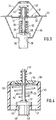
- the valve shown in FIGS. 1 and 2 has an essentially tubular housing (10) which is inserted into a connecting flange (11) and fixed in the axial direction with a stop (12).
- the connection (11) is preferably flanged to an engine outlet of an internal combustion engine, from which the coolant flowing through the internal combustion engine leaves the engine and flows, for example, to a thermostatic control valve.
- a flap (13) serving as a closure member is mounted in the housing (10) by means of a pivot axis (14).
- the pivot axis (14) is mounted in bearing receptacles (15) of the housing (10), which are located in the region of pocket-like recesses (16).
- the pivot axis (14) is a bolt which is pushed through the flap (13) and the bearing receptacles (15) and which is axially fixed by means of snap rings (17), for example spring washers, which are fitted on the outside. This securing is sufficient, since in the installed state the connection (11) prevents the pivot axis (14) from moving axially.
- the pivot axis (14) of the flap (13) is at a distance from the center point (18) of the flap (13) indicated in FIG. 2. An overpressure which arises on one side of the flap (13) thus leads to a torque with respect to the pivot axis (14) which tends to pivot the flap (13).
- the housing (13) is provided with valve seat surfaces (19, 20) which are assigned to the flap (13). These valve seat surfaces (19, 20) are at an axial distance which corresponds to the thickness of the flap (13). They are divided in the area of the pivot axis (14), so that the except for a recess in the region of the pivot axis (14), essentially semi-circular sealing surfaces (19, 20) are assigned to the inside and to the outside of the flap (13), ie the inside facing the flow direction (21) and the outside facing away from the flow direction.
- the flap (13) is loaded with a bow spring (22) on its outside, which holds the flap (13) in the closed position shown in FIG. 1.
- the ends of the bow spring (22), which is preferably preloaded, are inserted into recesses in the housing (10).
- the previously described elements of the valve thus form a pressure relief valve which opens when the flap (13) swings open in the event of overpressure.
- the size of the overpressure causing an opening is determined by the pretensioned bow spring (22).
- the valve is also designed as a temperature-dependent switching valve.
- a thermostatic working element (23) is provided as the switching element, which is held in a holder (24) of the housing (10), which is formed in one piece with the housing (10) by means of webs (25).
- the thermostatic working element (23) has a housing (26) in which an expansion material, in particular a wax mixture, is accommodated.
- the open end of the housing (26) is sealed with a sack-shaped membrane (27), which is tightly clamped by means of a guide insert (28).
- the working piston (29) engages the flap (13) at a distance from the pivot axis (14).
- the thermostatic working element (23) is arranged in the flow direction (21) in front of the flap (13).
- the thermostatic working element (23) responds to the temperature of the medium to be shut off, in particular a coolant of a cooling system of an internal combustion engine.
- the response temperature or opening temperature of the thermostatic working element (23), at which the working piston (29) begins its extension movement from the housing (26), is due to the choice of the expansion material Composition of the wax mixture, adjustable. In a cooling system of an internal combustion engine, this opening temperature is set in a range from 60 ° C to 80 ° C.
- the extending working piston (29) takes the flap (13) with it and thus opens the valve depending on the temperature.
- a flap as a closure element has the advantage that a relatively large flow cross section is released even with relatively small pivoting movements of the flap. Since there is no fixed connection between the working piston (29) and the flap (13), the working piston (29) can extend unhindered in the event of excess temperatures, ie temperatures exceeding its opening temperature.
- the bow spring (22) in such a way that it also serves as a return spring for the thermostatic working element (23), ie when the temperature drops below the opening temperature Push the working piston (29) back into its starting position in the housing (26).
- the working piston (29) is assigned its own return spring (30). This return spring (30) is supported between an extension of the guide insert (28) and a spring plate (31) attached to the working piston (29).
- a tension spring is provided instead of a bow spring (22), which is attached between one of the webs (25) and the flap (13).
- a valve plate (31) serves as the closure member, to which a valve seat (32) is assigned, which is integrally formed on a sheet metal ring (33).
- the sheet metal ring (33) forms a circumferential flange, with the aid of which the entire valve can be clamped between an engine outlet and a connecting piece.
- a sheet metal bracket (34) is attached to the sheet metal ring (33) and forms a holder for a thermostatic working element (35), the structure of which corresponds to the thermostatic working element (23) according to FIG. 1.
- the thermostatic working element (35) has a housing (36) in which an expansion material, in particular a wax mixture, is accommodated, which drives a working piston (37) with linear movement at a temperature which can be predetermined by the choice of the wax mixture.
- the working piston (37) is guided in a guide part (38) which closes the housing (36) and forms an abutment for a return spring (39).
- the return spring (39) is supported on a spring plate (40) attached to the working piston (37) and presses it into the housing (36), i.e. in its closed position.
- the one-part or multi-part working piston (37) is extended beyond the guide part (38) and provided with a driving plate (41) for the valve plate (31).
- the valve disc (31) is provided with a cap-like shape (42) with which it is movably guided on the working piston (37).
- the valve plate (31) is also loaded with a coil spring (43) in the closing direction, which counteracts supports a bracket (44) attached to the sheet metal ring (33).
- the return spring (39) is designed so that it presses the working piston (37) securely into the housing (36) when it cools down or the response temperature. This requires a relatively large force, which can be of the order of 10 N.
- the function of the switching element, i.e. the thermostatic working element (35), independent spring (43), on the other hand, is designed such that it is compressed by an overpressure of a certain size occurring on the side of the valve plate (31) facing away from it, by the force acting on the valve plate (31), so that the valve works as a pressure relief valve.
- the size of the overpressure at which the valve acts and opens as a relief valve can be determined by the choice of the spring stiffness (43) and the preload.
- the shape (42) or a bolt attached to the valve plate (31) in its place is guided in the bracket (44), which is provided with a corresponding guide recess.
- the working piston (37) can be shortened, which is then supported only against the side of the valve plate (31) facing away from the spring (43).
- valve according to FIG. 3 is used as a so-called warm-up valve for the cooling system of an internal combustion engine, it is expedient if a certain amount of flow is permitted through the closed valve, so that the heating coolant also cools the housing (36) in time thermostatic working element (35) reached, which serves as a sensing part.
- openings can be provided in the sheet metal ring forming the valve seat and / or the valve plate (31), the cross section of which is dimensioned such that the desired flow rate is obtained.
- Such small flow rates can also be realized by the design of the valve plate and the associated valve seat (32).
- a flap (13) similar to the exemplary embodiment according to FIGS. 1 and 2 is mounted on the sheet metal ring (33) serving as the fastening flange.
- the valve surfaces of the sheet metal ring are then designed in a manner similar to that in the exemplary embodiment according to FIGS. 1 and 2.
- an essentially tubular housing (45) is provided corresponding to the exemplary embodiment according to FIG. 1, which is preferably made of plastic.
- This housing (45) can be inserted into a connecting piece in a manner corresponding to the housing (10) of the exemplary embodiment according to FIG. 1 and fixed there.
- the housing (45) is provided with a holder (46) which is connected to the outer part of the housing (45) via a plurality of webs (47).
- the holder (46) receives the housing (48) of a thermostatic working element, which is supported against the flow direction of the medium to be shut off by means of an annular collar on the holder (46).
- the housing (48) of the thermostatic working element (49) contains, in a known manner, an expansion material which drives a working piston (50) with linear movement when a certain temperature is reached.
- the working piston (50) is provided with a spring plate (51) which, in the closed position of the valve, bears against the housing (48) or a guide part for the working piston (50) held therein.
- a return spring (52) is supported on the spring plate (51), the other end of which is supported against an annular collar (53) of the housing (45).
- the return spring (52) is designed so that it presses the working piston (50) back safely into the housing (48) when the temperature drops.
- the annular collar (53) of the housing (45) also forms a valve seat for a valve plate (54), for example is also made of plastic.
- the valve disk (54) is slidably guided on the one-piece or multi-part working piston (50), which is extended beyond the annular collar (53).
- the working piston (50) is provided with a driver plate (55) which takes the valve plate (54) in the opening direction when the working piston (50) extends.
- valve plate (54) is loaded on the side opposite the driver plate (55) with a coil spring (56) which is supported on a spring plate (57) attached to the working piston (50).
- the spring (46) is designed by a suitable choice of its characteristic curve and its preload so that the valve plate (54) moves in the opening direction at an overpressure of a predetermined size and thereby slides on the working piston (50).
- a flow of a certain size flows through the valve even when the valve is closed.
- corresponding openings can be provided in the annular collar (53) and / or in the valve plate (54) or in the valve sealing surfaces on both sides.
- the exemplary embodiment according to FIG. 3 can also be modified in such a way that the valve plate (31) is guided on the working piston (37) in a manner similar to the exemplary embodiment according to FIG. 4, the spring (43) then also being attached to one of the working pistons ( 37) attached spring plate is supported.
- 3 can be modified so that the return spring (39) is similar to the embodiment of FIG. 4 and is supported on the spring plate (40) and the sheet metal ring (33).
- valve disk (54) is provided with one (or more) guide bolts, which are then guided in guide arms (not shown) projecting inwards from the extended housing (45), on which the spring (56) is then also supported.
- another temperature-dependent switching element is provided instead of the thermostatic working element.
- a bimetal switching element in particular one or more bimetal disks.
- a spring which consists of a so-called shape-memory alloy. Such a spring then also has the function of a switching element which switches depending on a predetermined temperature.
Landscapes
- Engineering & Computer Science (AREA)
- General Engineering & Computer Science (AREA)
- Mechanical Engineering (AREA)
- Physics & Mathematics (AREA)
- Fluid Mechanics (AREA)
- General Physics & Mathematics (AREA)
- Automation & Control Theory (AREA)
- Temperature-Responsive Valves (AREA)
Priority Applications (3)
| Application Number | Priority Date | Filing Date | Title |
|---|---|---|---|
| JP01364396A JP3810843B2 (ja) | 1995-03-31 | 1996-01-30 | バルブ |
| US08/620,656 US5738276A (en) | 1995-03-31 | 1996-03-22 | Valve |
| BR9601163A BR9601163A (pt) | 1995-03-31 | 1996-03-28 | Válvula |
Applications Claiming Priority (2)
| Application Number | Priority Date | Filing Date | Title |
|---|---|---|---|
| DE19512046A DE19512046A1 (de) | 1995-03-31 | 1995-03-31 | Ventil |
| DE19512046 | 1995-03-31 |
Publications (3)
| Publication Number | Publication Date |
|---|---|
| EP0735301A2 true EP0735301A2 (fr) | 1996-10-02 |
| EP0735301A3 EP0735301A3 (fr) | 1997-12-03 |
| EP0735301B1 EP0735301B1 (fr) | 2001-10-04 |
Family
ID=7758397
Family Applications (1)
| Application Number | Title | Priority Date | Filing Date |
|---|---|---|---|
| EP95119289A Expired - Lifetime EP0735301B1 (fr) | 1995-03-31 | 1995-12-07 | Robinet thermostatique |
Country Status (2)
| Country | Link |
|---|---|
| EP (1) | EP0735301B1 (fr) |
| DE (2) | DE19512046A1 (fr) |
Cited By (4)
| Publication number | Priority date | Publication date | Assignee | Title |
|---|---|---|---|---|
| EP1394648A1 (fr) * | 2002-08-21 | 2004-03-03 | Honeywell Normalair-Garrett (Holdings) Limited | Soupape thermostatique |
| FR2851314A1 (fr) * | 2003-02-19 | 2004-08-20 | Mark Iv Systemes Moteurs Sa | Dispositif a clapet(s) controlant la circulation d'un fluide entre deux volumes |
| DE102006050825A1 (de) * | 2006-10-27 | 2008-04-03 | Audi Ag | Mehrwegeventil mit einem Betätigungselement und mindestens zwei Querschnittsverstellgliedern |
| GB2586598A (en) * | 2019-08-26 | 2021-03-03 | John Hudson Raymond | Dynamic control valve |
Families Citing this family (1)
| Publication number | Priority date | Publication date | Assignee | Title |
|---|---|---|---|---|
| DE102008031544A1 (de) * | 2008-07-07 | 2010-01-21 | Dichtungstechnik G. Bruss Gmbh & Co. Kg | Federzungenventil für eine Ölabscheidevorrichtung für die Kurbelgehäuseentlüftung eines Kraftfahrzeugs |
Family Cites Families (19)
| Publication number | Priority date | Publication date | Assignee | Title |
|---|---|---|---|---|
| US1112135A (en) * | 1913-05-09 | 1914-09-29 | John William Harkom | Valve. |
| GB357735A (en) * | 1930-08-25 | 1931-10-01 | William Herbert Carson | Improvements in control valves or cocks |
| US2569359A (en) * | 1948-07-08 | 1951-09-25 | Dole Valve Co | Thermostatic valve |
| US3166294A (en) * | 1961-05-01 | 1965-01-19 | Ford Motor Co | Butterfly valve |
| US3292856A (en) * | 1964-11-16 | 1966-12-20 | Gen Motors Corp | Shaftless unbalanced thermostatic valve |
| GB1446704A (en) * | 1972-07-29 | 1976-08-18 | Nat Vulcan Eng Insurance Group | Valves |
| SE383401B (sv) * | 1973-06-08 | 1976-03-08 | Saab Scania Ab | Anordning vid backventiler av det slag som har ett ventilhus med rakt genomlopp och med ett cirkulert ventilsete anordnat lengs ett genomloppets symmetrilinje korsande plan, och ett spjell, som er vridbart m.m |
| US3893618A (en) * | 1973-08-01 | 1975-07-08 | Standard Thomson Corp | Thermostatic valve device having non-linear flow characteristics |
| CH641259A5 (de) * | 1979-10-09 | 1984-02-15 | Fischer Ag Georg | Absperrklappe. |
| US4283006A (en) * | 1980-07-10 | 1981-08-11 | Fedewitz James A | Thermally-activated closure device |
| US4380246A (en) * | 1981-03-20 | 1983-04-19 | Dayco Corporation | Butterfly valve and method of making same |
| US4399940A (en) * | 1982-04-23 | 1983-08-23 | Stiles Donald E | Automatic stove damper control |
| DE8513209U1 (de) * | 1985-05-04 | 1985-06-20 | Behr-Thomson Dehnstoffregler Gmbh, 7014 Kornwestheim | Thermostatventil |
| SU1541452A1 (ru) * | 1988-01-27 | 1990-02-07 | Юго-Восточное производственно-техническое предприятие "Ювэнергочермет" | Дроссельный клапан |
| DE3838547A1 (de) * | 1988-11-14 | 1990-05-17 | Weinhold Karl | Rueckschlagklappe |
| US4978060A (en) * | 1990-03-15 | 1990-12-18 | Eaton Corporation | Engine coolant thermostat with pressure relief feature |
| US5048751A (en) * | 1990-04-16 | 1991-09-17 | Outboard Marine Corporation | Pressure and temperature relief valve and diaphragm valve |
| US5186385A (en) * | 1990-07-10 | 1993-02-16 | Majco Building Specialties, L.P. | Thermally activated vent damper |
| US5305787A (en) * | 1993-02-03 | 1994-04-26 | C & S Valve Company | Disk valve with improved disk mounting |
-
1995
- 1995-03-31 DE DE19512046A patent/DE19512046A1/de not_active Withdrawn
- 1995-12-07 EP EP95119289A patent/EP0735301B1/fr not_active Expired - Lifetime
- 1995-12-07 DE DE59509660T patent/DE59509660D1/de not_active Expired - Lifetime
Cited By (4)
| Publication number | Priority date | Publication date | Assignee | Title |
|---|---|---|---|---|
| EP1394648A1 (fr) * | 2002-08-21 | 2004-03-03 | Honeywell Normalair-Garrett (Holdings) Limited | Soupape thermostatique |
| FR2851314A1 (fr) * | 2003-02-19 | 2004-08-20 | Mark Iv Systemes Moteurs Sa | Dispositif a clapet(s) controlant la circulation d'un fluide entre deux volumes |
| DE102006050825A1 (de) * | 2006-10-27 | 2008-04-03 | Audi Ag | Mehrwegeventil mit einem Betätigungselement und mindestens zwei Querschnittsverstellgliedern |
| GB2586598A (en) * | 2019-08-26 | 2021-03-03 | John Hudson Raymond | Dynamic control valve |
Also Published As
| Publication number | Publication date |
|---|---|
| EP0735301B1 (fr) | 2001-10-04 |
| DE59509660D1 (de) | 2001-11-08 |
| EP0735301A3 (fr) | 1997-12-03 |
| DE19512046A1 (de) | 1996-10-02 |
Similar Documents
| Publication | Publication Date | Title |
|---|---|---|
| DE3445664C2 (fr) | ||
| EP2181375B1 (fr) | Soupape de sûreté thermostatique | |
| DE112009003644T5 (de) | Thermisches Umgehungsventil mit Druckentlastungsfähigkeit | |
| DE69116514T2 (de) | Mit einer Wachskapsel betriebener und mit einer Sicherheitsvorrichtung versehener Thermostat | |
| EP1711698B1 (fr) | Ensemble soupape thermostatique | |
| DE102004020589B4 (de) | Temperaturabhängiges Strömungsregelventil für Motorkühlsysteme mit einer rohrförmigen Ventilspule | |
| DE9109600U1 (de) | Thermostatventil mit einem Vorsteuerventil | |
| DE102019000836B4 (de) | Thermostatvorrichtung für ein Kühlsystem | |
| DE4325975C9 (de) | Thermostatventil | |
| EP0484624B1 (fr) | Soupape thermostatique pour la régulation de la température du liquide de refroidissement d'un moteur à combustion interne | |
| DE102005018904B3 (de) | Thermostatventil für das Kühlsystem einer Verbrennungskraftmaschine | |
| DE4106081A1 (de) | Thermostatventil zur regelung der temperatur der kuehlfluessigkeit einer brennkraftmaschine, insbesondere eines kraftfahrzeugmotors | |
| DE112020006222T5 (de) | Vorrichtung zum Steuern der Strömung eines Fluids | |
| DE9218709U1 (de) | Wärme- und Strömungsregulator mit integrierter Strömungs-Optimiereinrichtung | |
| EP1350551B1 (fr) | Dispositif à vannes, particulièrement pour le circuit de graissage d'un moteur à combustion interne, comprennant une vanne à contourner et une vanne unidirectionale | |
| DE2435966C2 (de) | Temperaturabhängiges Fluid-Ventil | |
| DE2653610A1 (de) | Thermostatanordnung | |
| DE102016205458A1 (de) | Thermostatisches Arbeitselement | |
| EP0735301B1 (fr) | Robinet thermostatique | |
| DE2755462B1 (de) | Thermostatisches Regelventil | |
| DE102004035344B4 (de) | Thermostatventil | |
| DE102007039109A1 (de) | Druckregelventil | |
| DE102008064704B4 (de) | Temperaturregelventil zur temperaturabhängigen Durchflussregelung von insbesondere Motoröl | |
| DE102014213938B3 (de) | Ventilanordnung | |
| DE19753551C2 (de) | Thermostatventil zur Regelung der Temperatur einer Druck- und Steuerflüssigkeit über eine By-Pass Verbindung |
Legal Events
| Date | Code | Title | Description |
|---|---|---|---|
| PUAI | Public reference made under article 153(3) epc to a published international application that has entered the european phase |
Free format text: ORIGINAL CODE: 0009012 |
|
| AK | Designated contracting states |
Kind code of ref document: A2 Designated state(s): DE FR GB IT |
|
| RAP1 | Party data changed (applicant data changed or rights of an application transferred) |
Owner name: BEHR THERMOT-TRONIK GMBH & CO. |
|
| PUAL | Search report despatched |
Free format text: ORIGINAL CODE: 0009013 |
|
| AK | Designated contracting states |
Kind code of ref document: A3 Designated state(s): DE FR GB IT |
|
| 17P | Request for examination filed |
Effective date: 19971219 |
|
| 17Q | First examination report despatched |
Effective date: 19991028 |
|
| GRAG | Despatch of communication of intention to grant |
Free format text: ORIGINAL CODE: EPIDOS AGRA |
|
| GRAG | Despatch of communication of intention to grant |
Free format text: ORIGINAL CODE: EPIDOS AGRA |
|
| GRAH | Despatch of communication of intention to grant a patent |
Free format text: ORIGINAL CODE: EPIDOS IGRA |
|
| GRAH | Despatch of communication of intention to grant a patent |
Free format text: ORIGINAL CODE: EPIDOS IGRA |
|
| GRAA | (expected) grant |
Free format text: ORIGINAL CODE: 0009210 |
|
| AK | Designated contracting states |
Kind code of ref document: B1 Designated state(s): DE FR GB IT |
|
| PG25 | Lapsed in a contracting state [announced via postgrant information from national office to epo] |
Ref country code: IT Free format text: LAPSE BECAUSE OF FAILURE TO SUBMIT A TRANSLATION OF THE DESCRIPTION OR TO PAY THE FEE WITHIN THE PRE;WARNING: LAPSES OF ITALIAN PATENTS WITH EFFECTIVE DATE BEFORE 2007 MAY HAVE OCCURRED AT ANY TIME BEFORE 2007. THE CORRECT EFFECTIVE DATE MAY BE DIFFERENT FROM THE ONE RECORDED.SCRIBED TIME-LIMIT Effective date: 20011004 Ref country code: GB Free format text: LAPSE BECAUSE OF FAILURE TO SUBMIT A TRANSLATION OF THE DESCRIPTION OR TO PAY THE FEE WITHIN THE PRESCRIBED TIME-LIMIT Effective date: 20011004 Ref country code: FR Free format text: LAPSE BECAUSE OF NON-PAYMENT OF DUE FEES Effective date: 20011004 |
|
| REF | Corresponds to: |
Ref document number: 59509660 Country of ref document: DE Date of ref document: 20011108 |
|
| GBV | Gb: ep patent (uk) treated as always having been void in accordance with gb section 77(7)/1977 [no translation filed] |
Effective date: 20011004 |
|
| EN | Fr: translation not filed | ||
| PLBE | No opposition filed within time limit |
Free format text: ORIGINAL CODE: 0009261 |
|
| STAA | Information on the status of an ep patent application or granted ep patent |
Free format text: STATUS: NO OPPOSITION FILED WITHIN TIME LIMIT |
|
| 26N | No opposition filed | ||
| REG | Reference to a national code |
Ref country code: FR Ref legal event code: ST |
|
| REG | Reference to a national code |
Ref country code: DE Ref legal event code: R084 Ref document number: 59509660 Country of ref document: DE Effective date: 20110711 |
|
| REG | Reference to a national code |
Ref country code: DE Ref legal event code: R082 Ref document number: 59509660 Country of ref document: DE Representative=s name: GRAUEL, ANDREAS, DIPL.-PHYS. DR. RER. NAT., DE Ref country code: DE Ref legal event code: R082 Ref document number: 59509660 Country of ref document: DE Representative=s name: ANDREAS GRAUEL, DE |
|
| REG | Reference to a national code |
Ref country code: DE Ref legal event code: R409 Ref document number: 59509660 Country of ref document: DE |
|
| REG | Reference to a national code |
Ref country code: DE Ref legal event code: R119 Ref document number: 59509660 Country of ref document: DE Effective date: 20120703 |
|
| PG25 | Lapsed in a contracting state [announced via postgrant information from national office to epo] |
Ref country code: DE Free format text: LAPSE BECAUSE OF NON-PAYMENT OF DUE FEES Effective date: 20120703 |
|
| REG | Reference to a national code |
Ref country code: DE Ref legal event code: R409 Ref document number: 59509660 Country of ref document: DE |
|
| REG | Reference to a national code |
Ref country code: DE Ref legal event code: R409 Ref document number: 59509660 Country of ref document: DE |
|
| PGRI | Patent reinstated in contracting state [announced from national office to epo] |
Ref country code: DE Effective date: 20130507 |
|
| PGFP | Annual fee paid to national office [announced via postgrant information from national office to epo] |
Ref country code: DE Payment date: 20141222 Year of fee payment: 20 |
|
| REG | Reference to a national code |
Ref country code: DE Ref legal event code: R071 Ref document number: 59509660 Country of ref document: DE |