EP0735314A1 - Anbaugehäuse für eine Lampenfassung in Leuchtengehäusen - Google Patents
Anbaugehäuse für eine Lampenfassung in Leuchtengehäusen Download PDFInfo
- Publication number
- EP0735314A1 EP0735314A1 EP96103253A EP96103253A EP0735314A1 EP 0735314 A1 EP0735314 A1 EP 0735314A1 EP 96103253 A EP96103253 A EP 96103253A EP 96103253 A EP96103253 A EP 96103253A EP 0735314 A1 EP0735314 A1 EP 0735314A1
- Authority
- EP
- European Patent Office
- Prior art keywords
- housing
- lamp
- add
- lamp holder
- conductor
- Prior art date
- Legal status (The legal status is an assumption and is not a legal conclusion. Google has not performed a legal analysis and makes no representation as to the accuracy of the status listed.)
- Granted
Links
- 239000004020 conductor Substances 0.000 claims description 40
- 238000003780 insertion Methods 0.000 claims description 8
- 230000037431 insertion Effects 0.000 claims description 8
- 238000004873 anchoring Methods 0.000 claims description 4
- 210000002105 tongue Anatomy 0.000 claims description 3
- 239000011810 insulating material Substances 0.000 claims description 2
- 239000007858 starting material Substances 0.000 abstract description 3
- 239000003990 capacitor Substances 0.000 description 3
- 238000009434 installation Methods 0.000 description 3
- 238000002347 injection Methods 0.000 description 2
- 239000007924 injection Substances 0.000 description 2
- 238000000034 method Methods 0.000 description 2
- 238000005452 bending Methods 0.000 description 1
- 239000000463 material Substances 0.000 description 1
Images

Classifications
-
- H—ELECTRICITY
- H01—ELECTRIC ELEMENTS
- H01R—ELECTRICALLY-CONDUCTIVE CONNECTIONS; STRUCTURAL ASSOCIATIONS OF A PLURALITY OF MUTUALLY-INSULATED ELECTRICAL CONNECTING ELEMENTS; COUPLING DEVICES; CURRENT COLLECTORS
- H01R33/00—Coupling devices specially adapted for supporting apparatus and having one part acting as a holder providing support and electrical connection via a counterpart which is structurally associated with the apparatus, e.g. lamp holders; Separate parts thereof
- H01R33/05—Two-pole devices
- H01R33/06—Two-pole devices with two current-carrying pins, blades or analogous contacts, having their axes parallel to each other
- H01R33/08—Two-pole devices with two current-carrying pins, blades or analogous contacts, having their axes parallel to each other for supporting tubular fluorescent lamp
- H01R33/0863—Two-pole devices with two current-carrying pins, blades or analogous contacts, having their axes parallel to each other for supporting tubular fluorescent lamp characterised by the mounting means
- H01R33/0872—Two-pole devices with two current-carrying pins, blades or analogous contacts, having their axes parallel to each other for supporting tubular fluorescent lamp characterised by the mounting means for mounting in an opening of a structure
-
- F—MECHANICAL ENGINEERING; LIGHTING; HEATING; WEAPONS; BLASTING
- F21—LIGHTING
- F21S—NON-PORTABLE LIGHTING DEVICES; SYSTEMS THEREOF; VEHICLE LIGHTING DEVICES SPECIALLY ADAPTED FOR VEHICLE EXTERIORS
- F21S8/00—Lighting devices intended for fixed installation
- F21S8/02—Lighting devices intended for fixed installation of recess-mounted type, e.g. downlighters
-
- F—MECHANICAL ENGINEERING; LIGHTING; HEATING; WEAPONS; BLASTING
- F21—LIGHTING
- F21V—FUNCTIONAL FEATURES OR DETAILS OF LIGHTING DEVICES OR SYSTEMS THEREOF; STRUCTURAL COMBINATIONS OF LIGHTING DEVICES WITH OTHER ARTICLES, NOT OTHERWISE PROVIDED FOR
- F21V19/00—Fastening of light sources or lamp holders
- F21V19/0075—Fastening of light sources or lamp holders of tubular light sources, e.g. ring-shaped fluorescent light sources
- F21V19/008—Fastening of light sources or lamp holders of tubular light sources, e.g. ring-shaped fluorescent light sources of straight tubular light sources, e.g. straight fluorescent tubes, soffit lamps
-
- F—MECHANICAL ENGINEERING; LIGHTING; HEATING; WEAPONS; BLASTING
- F21—LIGHTING
- F21V—FUNCTIONAL FEATURES OR DETAILS OF LIGHTING DEVICES OR SYSTEMS THEREOF; STRUCTURAL COMBINATIONS OF LIGHTING DEVICES WITH OTHER ARTICLES, NOT OTHERWISE PROVIDED FOR
- F21V23/00—Arrangement of electric circuit elements in or on lighting devices
-
- F—MECHANICAL ENGINEERING; LIGHTING; HEATING; WEAPONS; BLASTING
- F21—LIGHTING
- F21Y—INDEXING SCHEME ASSOCIATED WITH SUBCLASSES F21K, F21L, F21S and F21V, RELATING TO THE FORM OR THE KIND OF THE LIGHT SOURCES OR OF THE COLOUR OF THE LIGHT EMITTED
- F21Y2103/00—Elongate light sources, e.g. fluorescent tubes
Definitions
- the invention relates to an attachment housing for a lamp body wall for or with a lamp holder mounted or mountable in it, wherein the add-on housing made of insulating material is approximately pot-shaped with a bottom, side walls and an opening pointing into the lamp interior, the edge of which engages with latching means Anchoring of the pot attached with its bottom with respect to the lamp body wall facing outwards is assigned to a section of the lamp body wall and the lamp holder is to be attached near the floor inside the pot.
- a special feature of in particular fluorescent lamp recessed luminaires for grid ceilings is that the trough-shaped lamp bodies are too short in relation to the fluorescent lamps to be used due to the lamp grid dimensions. It is therefore customary to arrange the lamp sockets in an attachment housing at one end of the lamp, which is also called a “mounting box” or “backpack”. and enlarged the lamp installation space beyond the lamp body wall.
- the add-on housing manufactured as a plastic injection molded part is a pot-shaped box and is inserted from the inside of the luminaire body with its bottom through a cutout in the luminaire body wall until its flange edge on the open pot side engages with the cutout of the luminaire body wall.
- the bottom of the attachment housing has brackets, for example in the form of openings for engaging fastening locking pins of the lamp holder.
- the invention is therefore essentially based on the object of proposing an attachment housing for a lamp body wall for or with a lamp holder mounted or mountable in it, the new arrangement and design of which simplifies manual, but in particular also automatic wiring.
- the attachment housing is provided with guides for one conductor each, which, Starting near the rim of the pot, extend to near the respective conductor insertion opening of the lamp socket designed as a snap-in socket with a conductor insertion opening accessible from the front.
- both the manual and the automatic fitting of the lamp body as well as the wiring, i.e. the manual or automatic connection of conductors to the lamp holder to be accommodated in the attachment housing is considerably simplified.
- the lamp holder can first be preassembled in the add-on housing and this assembly can then be locked in the luminaire body wall. Only then are the conductors with their stripped ends inserted into the screwless terminals of the socket, specifically from the interior of the luminaire body, that is - see P 44 31 254.7 - in the course of the work process typical of the installation tool shown there.
- the guides which are preferably designed as guide channels that are matched to the conductor diameter in such a way that the conductor can be freely pushed forward while guaranteeing stress-free guidance and its stripped conductor ends can be inserted into the socket-side plug contacts of the screwless connecting terminals without kinks, guide the manually or automatically inserted free conductor ends, i.e. conductor sections of several centimeters in length, unhindered from the level of the luminaire body wall into the connection terminals of the luminaire socket, with kinking, bending or any other handicap is absolutely excluded as a result of the tours.
- FIG. 1 shows a ceiling louvre recessed luminaire, designated overall by 10, for two tube-shaped fluorescent lamps, not shown, on the end face.
- Two mechanical lamp holders 11 are used for the mechanical mounting and the electrical connection of the lamps, two of which are arranged on a lamp body end wall 12 and the other two in attachment housings denoted by 13.
- FIG. 1 Further components of a fluorescent lamp are, as shown in FIG. 1: an electrical connection terminal 14, two ballasts 15, a capacitor socket 16, and two starters 17 with the associated starter sockets 18.
- a capacitor 19 can be connected to the capacitor socket 16 for any compensation that may be required .
- These components are electrically connected to one another by means of a necessary large number of conductor sections 21, and line holders 20 serve for the clear and, above all, secure fixing of the lines.
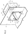
- each lamp While each lamp reaches just up to the lamp body end wall 12 at one end, it protrudes with its opposite end beyond the corresponding end wall 22 and plunges into an installation space artificially extended by an attachment housing 13.
- the add-on housing also known as "backpacks" in technical jargon, is made from the interior of the trough-shaped lamp body 10 pushed through a cutout 23 in the luminaire body wall 22 and latch on the edge of the cutout 23 with the aid of barb-like latching tongues 24 molded close to the flange edge.
- the attachment housing 13 is essentially pot-shaped with a bottom 25, four side walls 26, 27, 28 and 29 and with a flange 30 its open side.
- the mentioned locking means 24 are molded onto the flange 30.
- the attachment housing is a one-piece injection molded part made of plastic.
- a fluorescent lamp socket 31 is to be arranged near its base 25 in the interior of the attachment housing 13. This can be done in a pre-assembly step before the assembly housing / lamp socket 13/31 is then anchored in the wall cutout 23 of the lamp body end wall 22. However, as will be described further below, it is also possible to insert the lamp holder 31 into the add-on housing only when it has already been attached to the lamp body wall 22.
- two guides 32 are arranged in the form of at least largely closed-walled channels (the recognizable longitudinal slots are solely due to their shape), which extend from the flange 30, i.e. from the lamp body end wall 22 into the interior of the Extend the pot-shaped mounting housing 13 and open close to the associated conductor insertion openings 33 of the lamp holder 31, behind which the screwless conductor connection terminals are arranged in the insulating body of the lamp holder 31.
- the channel-like guides 32 have an essentially circular cross section, the diameter of which for the unimpeded insertion of a conductor is somewhat larger than the outside diameter of its insulating sheath. This ensures that a connecting wire with a stripped conductor end can be pushed forward without kinks and bends from the mouth 32a of the respective guide 32 and brought into contact with the contacts of the lamp holder 31.
- a second special feature of the illustrated embodiment is that the wall 29 of the attachment housing 13 has a wall opening 34. It is provided in the add-on housing wall which points in the same direction as the open side of the trough of the lamp body 10. The interior of the add-on housing 13 is therefore accessible from the same direction as the interior of the lamp body 10.
- the width of the cutout 34 is dimensioned in this way that a lamp holder 31 can be inserted into the mounting housing already mounted on the lamp body wall 22, either by hand or automatically with a robot suitable for component mounting.
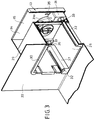
- the locking of the socket 31 in the operating position in the attachment housing 13 can take place automatically in any case, which is overlapped by the socket top side 31a Annex housing rear wall 15 molded locking tongues 35 is illustrated in Fig. 3.
- the end faces 36 of the material areas 37 containing the guides 32 form a secure guide in the correct position.
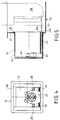
- FIG. 5 illustrates the connection of a conductor 21 with the aid of a robot-controlled conductor laying tool 38, which is able to donate the line in the required length, thus advancing the conductor relative to its own momentary position.
- the conductor laying tool 38 is positioned in front of the mouth 32a of the guide 32, and then the conductor 21 is conveyed until its stripped conductor end 21a has found a hold in the plug-in connection contacts within the lamp holder 13.
- the manual conductor connection can of course also be carried out in a simple manner simply by inserting the conductor 21 provided with a stripped end 21a.
Landscapes
- Engineering & Computer Science (AREA)
- General Engineering & Computer Science (AREA)
- Non-Portable Lighting Devices Or Systems Thereof (AREA)
- Fastening Of Light Sources Or Lamp Holders (AREA)
Abstract
Description
- Die Erfindung bezieht sich auf ein Anbaugehäuse für eine Leuchtenkörperwand für eine bzw. mit einer in ihm montierten bzw. montierbaren Lampenfassung, wobei das aus Isolierstoff bestehende Anbaugehäuse etwa topfförmig ausgebildet ist mit einem Boden, Seitenwänden und einer ins Leuchteninnere weisenden Öffnung, derem Rand Rastmittel zur Verankerung des mit seinem Boden bezüglich der Leuchtenkörperwand nach außen weisend angebrachten Topfes an einem Ausschnitt der Leuchtenkörperwand zugeordnet sind und die Lampenfassung bodennah im Innern des Topfes anzubringen ist.
- Bei insbesondere Leuchtstofflampen-Deckeneinbauleuchten für Rasterdecken besteht eine Besonderheit darin, daß die wannenförmigen Leuchtenkörper in Relation zu den zu verwendenden Leuchtstofflampen aufgrund der Leuchtenrastermaße eine zu geringe Länge aufweisen. Es ist deshalb üblich, an einem Stirnende der Leuchte die Lampenfassungen in einem Anbaugehäuse anzuordnen, das auch "Montagekasten" oder "Rucksack" genannt wird. und den Lampeneinbauraum über die Leuchtenkörperwand hinaus vergrößert. Das als Kunststoffspritzgießteil gefertigte Anbaugehäuse ist ein topfförmiger Kasten und wird von der Innenseite des Leuchtenkörpers mit seinem Boden voraus durch einen Ausschnitt in der Leuchtenkörperwand gesteckt, bis sein Flanschrand an der offenen Topfseite mit dem Ausschnitt der Leuchtenkörperwand verrastet. Der Boden des Anbaugehäuses weist Halterungen, z.B. in Form von Durchbrüchen auf zum Eingriff von Befestigungs-Rastzapfen der Lampenfassung.
- Diese besondere Anordnung und Ausgestaltung bringt einige Schwierigkeiten bei der Bestückung eines Leuchtenkörpers mit den Fassungen und im Zuge der Leiteranschlüsse mit sich. Bei manueller Verdrahtung geht man in der Regel so vor, daß man zunächst die Leiterenden in die Anschlußklemmen der betreffenden Fassung einsteckt, dann die Fassung in das Anbaugehäuse einrastet und dieses mit Fassung und angeschlossenen Leitern versehene Anbaugehäuse in der Leuchtenkörperwand verankert. Das ist umständlich.
- Noch größere Probleme treten dann auf, wenn eine Leuchte automatisch verdrahtet werden soll, z.B. nach dem Prinzip der noch nicht veröffentlichten Patentanmeldung P 44 38 254.7, vorzugsweise mit Hilfe eines Industrieroboters mit einem Leitungsverlegewerkzeug. Denn ohne besonderen Aufwand ist der Roboter nicht in der Lage, die Arbeitsschritte der soeben geschilderten manuellen Verdrahtung oder einer ähnlichen nachzuvollziehen. Hier müssen andere Wege beschritten werden.
- Der Erfindung liegt demzufolge im wesentlichen die Aufgabe zugrunde, ein Anbaugehäuse für eine Leuchtenkörperwand für eine bzw. mit einer in ihm montierten bzw. montierbaren Lampenfassung in Vorschlag zu bringen, dessen neue Anordnung und Gestaltung eine vereinfachte manuelle, insbesondere aber auch automatische Verdrahtung ermöglicht.
- Zur Lösung dieser Aufgabe ist das Anbaugehäuse mit Führungen für jeweils einen Leiter versehen, die sich, topfrandnah beginnend, bis nahe der jeweiligen Leitereinstecköffnung der als Steckrastfassung mit frontseitig zugänglichen Leitereinstecköffnung ausgeführten Lampenfassung erstrecken.
- Als Folge dieser Ausgestaltung des Anbaugehäuses ist sowohl die manuelle als auch eine automatische Bestückung des Leuchtenkörpers wie auch die Verdrahtung, d.h. der manuelle oder automatische Anschluß von Leitern an die im Anbaugehäuse aufzunehmende Lampenfassung wesentlich vereinfacht. Dazu kann zunächst die Lampenfassung allein im Anbaugehäuse vormontiert sein und diese Baugruppe dann in der Leuchtenkörperwand verrastet werden. Erst daraufhin werden die Leiter mit ihren abisolierten Enden in die schraubenlosen Anschlußklemmen der Fassung eingeschoben, und zwar vom Innenraum des Leuchtenkörpers her, also - siehe P 44 31 254.7 - im Zuge des dem dort dargestellten Verlegewerkzeugs typischen Arbeitsfortgangs.
- Die Führungen, die vorzugsweise als derart auf den Leiterdurchmesser abgestimmte Führungskanäle ausgebildet sind, daß die Leiter unter Gewährleistung knickbeanspruchungsfreier Führung frei vorschiebbar und ihre abisolierten Leiterenden knickfrei in die fassungsseitigen Steckkontakte der schraubenlosen Anschlußklemmen einsteckbar sind, führen die manuell oder automatisch einzuführenden freien Leiterenden, also Leiterabschnitte von mehreren Zentimetern Länge, behinderungsfrei von der Ebene der Leuchtenkörperwand bis hinein in die Anschlußklemmen der Leuchtenfassung, wobei ein Verknicken, Verbiegen oder eine sonstige Behinderung infolge der Führungen absolut ausgeschlossen ist. Bei der manuellen Bestückung erlaubt es diese Anordnung, daß die Leiter gewissermaßen blind eingesteckt werden können, bei der automatischen Verdrahtung muß lediglich eine für das Vorschieben des Leiters erforderliche Leiterüberlänge ausgebildet sein, was jedoch keinerlei Schwierigkeiten bereitet, da die Leiterfördereinrichtung im Verlegewerkzeug in Lage ist, eine vorberechnete Leiterlänge zu spenden (P 44 31 254.7).
- Weitere vorteilhafte und zweckmäßige Ausgestaltungen sind in den weiteren Unteransprüchen angegeben und auch aus der nachfolgenden Beschreibung der Erfindung anhand eines bevorzugten Ausführungsbeispiels im einzelnen beschrieben. In den Zeichnungen zeigen:
- Fig. 1
- eine schematische Darstellung eines mit den erforderlichen Bauelementen und Leiterzügen bestückten Leuchtenkörpers einer Leuchte für Leuchtstofflampen, die mit zwei Anbaugehäusen an der Leuchtenkörperstirnwand ausgerüstet ist,
- Fig. 2
- eine schaubildliche Darstellung eines mit einer Lampenfassung versehenen und in einer Leuchtenkörperwand einsteckenden Anbaugehäuses,
- Fig. 3
- die Darstellung nach Fig. 2 jedoch in teilweise längsgeschnittener Darstellung,
- Fig. 4
- eine Stirnansicht mit Blickrichtung in das mit einer Lampenfassung bestückte Anbaugehäuse und
- Fig. 5
- einen Längsschnitt zur Veranschaulichung der Leiterbestückung der im Anbaugehäuse festgelegten Lampenfassung.
- Fig. 1 zeigt eine insgesamt mit 10 bezeichnete Deckenraster-Einbauleuchte für zwei nicht dargestellte, stirnseitig gesockelte Leuchtstofflampen in Röhrenform. Zur mechanischen Halterung und dem elektrischen Anschluß der Lampen dienen je zwei paarig angeordnete Lampenfassungen 11, von denen zwei an einer Leuchtenkörperstirnwand 12 und die beiden anderen in mit 13 bezeichneten Anbaugehäusen angeordnet sind.
- Weitere Bauelemente einer Leuchtstoffleuchte sind, wie in Fig. 1 gezeigt: eine elektrische Anschlußklemme 14, zwei Vorschaltgeräte 15, eine Kondensatorfassung 16, sowie zwei Starter 17 mit den zugehörigen Starterfassungen 18. Für eine eventuell erforderliche Kompensation ist ein Kondensator 19 an die Kondensatorfassung 16 anschließbar. Diese Bauelemente sind untereinander mittels einer notwendigen Vielzahl von Leiterabschnitten 21 elektrisch miteinander verbunden, und Leitungshalter 20 dienen der übersichtlichen wie vor allem sicheren Festlegung der Leitungen.
- Während jede Lampe an einem Ende knapp bis zur Leuchtenkörperstirnwand 12 heranreicht, ragt sie mit ihrem gegenüberliegenden Ende über die entsprechende Stirnwand 22 hinaus und taucht in einen durch jeweils ein Anbaugehäuse 13 künstlich verlängerten Einbauraum ein. Die Anbaugehäuse, im Fachjargon auch "Rucksäcke" genannt, werden vom Innenraum des wannenförmigen Leuchtenkörpers 10 aus durch einen Ausschnitt 23 in der Leuchtenkörperwand 22 geschoben und verrasten an dem Rand des Ausschnitts 23 mit Hilfe von flanschrandnah angeformten, widerhakenartigen Rastzungen 24.
- In Fig. 2 ist dies noch wesentlich deutlicher dargestellt, und zwar mit Blickrichtung aus dem Innenraum des Leuchtenkörpers 10. Das Anbaugehäuse 13 ist im wesentlichen topfartig ausgebildet mit einem Boden 25, vier Seitenwänden 26, 27, 28 und 29 sowie mit einem Flansch 30 an seiner offenen Seite. Dem Flansch 30 sind die genannten Rastmittel 24 angeformt. Insgesamt stellt das Anbaugehäuse ein einstückiges Spritzgußteil aus Kunststoff dar. Nahe seinem Boden 25 ist im Innenraum des Anbaugehäuses 13 eine Leuchtstofflampenfassung 31 anzuordnen. Dies kann in einem Vormontageschritt geschehen, bevor dann die Baueinheit Anbaugehäuse/Lampenfassung 13/31 im Wandausschnitt 23 der Leuchtenkörperstirnwand 22 verankert wird. Es ist jedoch, wie weiter unten noch beschrieben wird, auch möglich, die Lampenfassung 31 erst dann in das Anbaugehäuse einzusetzen, wenn dieses bereits an der Leuchtenkörperwand 22 angebracht worden ist.
- Bei dem in Fig. 2 dargestellten Ausführungsbeispiel bestehen im Hinblick auf die Erfindung einige Besonderheiten. Die wesentliche ist die, daß im Anbaugehäuse 13 zwei Führungen 32 im Form von zumindest weitestgehend geschlossenwandigen Kanälen angeordnet sind (die erkennbaren Längsschlitze sind allein formtechnisch bedingt), die sich vom Flansch 30, also von der Leuchtenkörperstirnwand 22 aus in den Innenraum des topfförmigen Anbaugehäuses 13 hineinerstrecken und dicht vor den zugeordneten Leitereinführöffnungen 33 der Lampenfassung 31 münden, hinter denen die schraubenlosen Leiter-Anschlußklemmen im Isolierkörper der Lampenfassung 31 angeordnet sind.
- Die kanalartigen Führungen 32 weisen einen im wesentlichen kreisförmigen Querschnitt aus, dessen Durchmesser zur behinderungsfreien Einführung eines Leiters etwas größer ist als der Außendurchmesser seiner Isolierumhüllung. Dadurch ist es gewährleistet, daß man einen Anschlußdraht mit abisoliertem Leiterende knick- und biegefrei von der Mündung 32a der jeweiligen Führung 32 vorschieben und in Kontaktstellung mit den Kontakten der Lampenfassung 31 bringen kann.
- Eine zweite Besonderheit des dargestellten Ausführungsbeispiels besteht darin, daß die Wand 29 des Anbaugehäuses 13 einen Wanddurchbruch 34 aufweist. Er ist in derjenigen Anbaugehäusewand vorgesehen, die in die gleiche Richtung weist wie die offene Seite der Wanne des Leuchtenkörpers 10. Der Innenraum des Anbaugehäuses 13 ist deshalb aus derselben Richtung her zugänglich wie der Innenraum des Leuchtenkörpers 10. Die Weite des Ausschnittes 34 ist so bemessen, daß eine Lampenfassung 31 in das bereits an der Leuchtenkörperwand 22 montierte Anbaugehäuse eingesetzt werden kann, und zwar entweder von Hand oder automatisch mit einem zur Bauelementbestückung geeigneten Roboter. Die Verrastung der Fassung 31 in Betriebslage im Anbaugehäuse 13 kann dabei in jedem Fall automatisch erfolgen, was durch die Fassungsoberseite 31a übergreifende, an der Anbaugehäuserückwand 15 ausgeformte Rastzungen 35 in Fig. 3 veranschaulicht ist. Die bodennahen Stirnseiten 36 der die Führungen 32 beinhaltenden Werkstoffbereiche 37 bilden beim Einsetzen der Lampenfassung 31 auf der dem Boden 15 zugewandten Seite eine sichere Führung in lagegerechter Zuordnung.
- Schließlich besteht noch eine Besonderheit darin, daß eine Lampenfassung 31 verwendet wird, deren Leitereinstecköffnungen 33 auf ihrer Frontseite liegen, also achsparallel zur Lampenachse verlaufen und somit auch achsparallel zu den Führungen 32. Fig. 5 veranschaulicht das Anschließen eines Leiters 21 mit Hilfe eines robotergesteuerten Leiterverlegewerkzeugs 38, welches in der Lage ist, die Leitung in benötigter Länge zu spenden, den Leiter also relativ zu seiner eigenen Momentanstellung vorzuschieben. Das Leiterverlegewerkzeug 38 wird vor die Mündung 32a der Führung 32 positioniert, und sodann der Leiter 21 gefördert, bis dessen abisoliertes Leiterende 21a in den Steckanschlußkontakten innerhalb der Lampenfassung 13 Halt gefunden hat. In gleicher Weise kann natürlich auch der manuelle Leiteranschluß auf einfache Art durch bloßes Einschieben des mit einem abisolierten Ende 21a versehenen Leiters 21 durchgeführt werden.
Claims (7)
- Anbaugehäuse für eine Leuchtenkörperwand für eine bzw. mit einer in ihm montierten bzw. montierbaren Lampenfassung, wobei das aus Isolierstoff bestehende Anbaugehäuse etwa topfförmig ausgebildet ist mit einem Boden, Seitenwänden und einer ins Leuchteninnere weisenden Öffnung, derem Rand Rastmittel zur Verankerung des mit seinem Boden bezüglich der Leuchtenkörperwand nach außen weisend angebrachten Topfes an einem Ausschnitt der Leuchtenkörperwand zugeordnet sind und die Lampenfassung bodennah im Innern des Topfes anzubringen ist, dadurch gekennzeichnet, daß das Anbaugehäuse (13) mit Führungen (32) für jeweils einen Leiter (21) versehen ist, die sich, topfrandnah beginnend, bis nahe der jeweiligen Leitereinstecköffnung (33) der als Steckrastfassung mit frontseitig zugänglichen Leitereinstecköffnung ausgeführten Lampenfassung (31) erstrecken.
- Anbaugehäuse nach Anspruch 1, dadurch gekennzeichnet, daß die Führungen (32) als derart auf die Leiterdurchmesser abgestimmte Führungskanäle ausgebildet sind, daß die Leiter (21) unter Gewährleistung knickbeanspruchungsfreier Führung frei vorschiebbar und ihre abisolierten Leiterenden (21a) knickfrei in die fassungsseitigen Steckkontakte der schraubenlosen Anschlußklemmen der Lampenfassung (31) einsteckbar sind.
- Anbaugehäuse nach Anspruch 1 oder 2, dadurch gekennzeichnet, daß mindestens eine Wand (29) des topfartigen Anbaugehäuses (13) eine bodennah angeordnete fensterartige Öffnung (34) aufweist, durch die eine Lampenfassung (31) - ggf. selbst bei bereits an der Leuchtenkörperwand (22) angebrachtem Anbaugehäuse (13) - von der Außenseite her in das Anbaugehäuse (13) einsetzbar ist.
- Anbaugehäuse nach einem Ansprüche 1 bis 3, gekennzeichnet durch Verwendung einer Lampenfassung (31) mit sich zum Boden (15) des Anbaugehäuses (13) im wesentlichen parallel und zur Lampenachse lotrecht erstreckenden Befestigungsorganen zur Rastverankerung an der der Wandöffnung (34) gegenüberliegenden Wand (26) des Anbaugehäuses (13).
- Anbaugehäuse nach einem Ansprüche 1 bis 3, gekennzeichnet durch Verwendung einer Lampenfassung (31) mit sich zum Boden (15) des Anbaugehäuses (13) im wesentlichen lotrecht und zur Lampenachse parallel erstreckenden Befestigungsorganen zur Rastverankerung am Boden (25) des Anbaugehäuses (13).
- Anbaugehäuse nach einem der Ansprüche 1 bis 3, dadurch gekennzeichnet, daß im Anbaugehäuse (13) etwa in Flucht zu der fensterartigen Öffnung (34) zwischen dem Boden (15) und der inneren Begrenzungsstirn (36) der Führung (32) eine Einschubtasche für eine Lampenfassung (31) ausgebildet ist und daß lediglich dem Anbaugehäuse (13) Mittel zur Halterung der Lampenfassung (31) angeformt sind.
- Anbaugehäuse nach Anspruch 6, dadurch gekennzeichnet, daß die Halterungsmittel (35) als die Lampenfassung (31) mindestens teilumgreifende Rastzungen ausgebildet sind.
Applications Claiming Priority (2)
| Application Number | Priority Date | Filing Date | Title |
|---|---|---|---|
| DE29505452U | 1995-03-31 | ||
| DE29505452U DE29505452U1 (de) | 1995-03-31 | 1995-03-31 | Anbaugehäuse für eine Lampenfassung in Leuchtengehäusen |
Publications (2)
| Publication Number | Publication Date |
|---|---|
| EP0735314A1 true EP0735314A1 (de) | 1996-10-02 |
| EP0735314B1 EP0735314B1 (de) | 1999-09-22 |
Family
ID=8006155
Family Applications (1)
| Application Number | Title | Priority Date | Filing Date |
|---|---|---|---|
| EP96103253A Expired - Lifetime EP0735314B1 (de) | 1995-03-31 | 1996-03-02 | Anbaugehäuse für eine Lampenfassung in Leuchtengehäusen |
Country Status (4)
| Country | Link |
|---|---|
| EP (1) | EP0735314B1 (de) |
| AT (1) | ATE184976T1 (de) |
| DE (2) | DE29505452U1 (de) |
| ES (1) | ES2138253T3 (de) |
Families Citing this family (1)
| Publication number | Priority date | Publication date | Assignee | Title |
|---|---|---|---|---|
| DE29614194U1 (de) * | 1996-08-16 | 1996-10-24 | Brökelmann, Jaeger & Busse GmbH & Co, 59755 Arnsberg | Anbaugehäuse für eine Lampenfassung in Leuchtengehäusen |
Citations (3)
| Publication number | Priority date | Publication date | Assignee | Title |
|---|---|---|---|---|
| FR2016439A1 (de) * | 1968-08-27 | 1970-05-08 | Vossloh Werke Gmbh | |
| DE2322138A1 (de) * | 1973-05-02 | 1974-11-14 | Philipp Dipl Ing Federspieler | Leuchte fuer leuchtstofflampen |
| US4863394A (en) * | 1985-05-20 | 1989-09-05 | General Electric Company | Electrical connector with double torsion contacts |
-
1995
- 1995-03-31 DE DE29505452U patent/DE29505452U1/de not_active Expired - Lifetime
-
1996
- 1996-03-02 EP EP96103253A patent/EP0735314B1/de not_active Expired - Lifetime
- 1996-03-02 DE DE59603117T patent/DE59603117D1/de not_active Expired - Lifetime
- 1996-03-02 AT AT96103253T patent/ATE184976T1/de not_active IP Right Cessation
- 1996-03-02 ES ES96103253T patent/ES2138253T3/es not_active Expired - Lifetime
Patent Citations (3)
| Publication number | Priority date | Publication date | Assignee | Title |
|---|---|---|---|---|
| FR2016439A1 (de) * | 1968-08-27 | 1970-05-08 | Vossloh Werke Gmbh | |
| DE2322138A1 (de) * | 1973-05-02 | 1974-11-14 | Philipp Dipl Ing Federspieler | Leuchte fuer leuchtstofflampen |
| US4863394A (en) * | 1985-05-20 | 1989-09-05 | General Electric Company | Electrical connector with double torsion contacts |
Also Published As
| Publication number | Publication date |
|---|---|
| EP0735314B1 (de) | 1999-09-22 |
| ATE184976T1 (de) | 1999-10-15 |
| ES2138253T3 (es) | 2000-01-01 |
| DE59603117D1 (de) | 1999-10-28 |
| DE29505452U1 (de) | 1995-06-01 |
Similar Documents
| Publication | Publication Date | Title |
|---|---|---|
| DE4433704C2 (de) | Steckbuchse | |
| EP1475565A2 (de) | Leuchtenanordnung | |
| EP0012234B1 (de) | Leuchtstofflampen-Set | |
| EP0140079B1 (de) | Installationssystem mit Zwischenstecker | |
| EP0893860B1 (de) | Anschlussgarnitur für Leuchtstofflampen | |
| EP0911914A1 (de) | Elektrisches Kupplungssystem | |
| EP0735314B1 (de) | Anbaugehäuse für eine Lampenfassung in Leuchtengehäusen | |
| DE3346826A1 (de) | Zubehoerhalter fuer eine leuchtenwand | |
| EP2007251A1 (de) | Möbel | |
| EP0825688B1 (de) | Elektronisches Vorschaltgerät für Tragschienenleuchten | |
| EP0621439A1 (de) | Lichtbandanordnung | |
| EP0825381B1 (de) | Anbaugehäuse für eine Lampenfassung in Leuchtengehäusen | |
| DE102008036936B4 (de) | Verfahren zur Montage einer Langfeldleuchte | |
| EP0787944B1 (de) | Platzsparende Fassung | |
| DE29505451U1 (de) | Anbaugehäuse für eine Lampenfassung in Leuchtengehäusen | |
| DE4013970C2 (de) | Sockelkörper | |
| DE10355192B4 (de) | Anschlusselement | |
| DE19710055C2 (de) | Kabelübergangs- und Sicherungskasten | |
| EP0114621B1 (de) | Leuchte und Verfahren zu ihrer Montage | |
| EP0027499B1 (de) | Bauteilesatz für Leuchtenbefestigung | |
| DE102018131996B4 (de) | Leuchte und zu deren Realisierung vorgesehenes System und Verfahren | |
| WO2025181284A1 (de) | Lichtband mit indirektkomponente | |
| EP0802587B1 (de) | Montagekasten mit einer Lampenfassung für Zweistift-Leuchtstofflampen oder dergleichen | |
| DE7702596U1 (de) | Zusatzgeraet mit einer oder mehreren steckdosen fuer leuchten | |
| DE29612393U1 (de) | Lampenfassung für durchverdrahtete Einbauleuchten |
Legal Events
| Date | Code | Title | Description |
|---|---|---|---|
| PUAI | Public reference made under article 153(3) epc to a published international application that has entered the european phase |
Free format text: ORIGINAL CODE: 0009012 |
|
| AK | Designated contracting states |
Kind code of ref document: A1 Designated state(s): AT DE ES FI FR GB IT NL SE |
|
| 17P | Request for examination filed |
Effective date: 19960816 |
|
| 17Q | First examination report despatched |
Effective date: 19981005 |
|
| GRAG | Despatch of communication of intention to grant |
Free format text: ORIGINAL CODE: EPIDOS AGRA |
|
| GRAG | Despatch of communication of intention to grant |
Free format text: ORIGINAL CODE: EPIDOS AGRA |
|
| GRAH | Despatch of communication of intention to grant a patent |
Free format text: ORIGINAL CODE: EPIDOS IGRA |
|
| ITF | It: translation for a ep patent filed | ||
| GRAH | Despatch of communication of intention to grant a patent |
Free format text: ORIGINAL CODE: EPIDOS IGRA |
|
| GRAA | (expected) grant |
Free format text: ORIGINAL CODE: 0009210 |
|
| AK | Designated contracting states |
Kind code of ref document: B1 Designated state(s): AT DE ES FI FR GB IT NL SE |
|
| REF | Corresponds to: |
Ref document number: 184976 Country of ref document: AT Date of ref document: 19991015 Kind code of ref document: T |
|
| GBT | Gb: translation of ep patent filed (gb section 77(6)(a)/1977) |
Effective date: 19990922 |
|
| ET | Fr: translation filed | ||
| REF | Corresponds to: |
Ref document number: 59603117 Country of ref document: DE Date of ref document: 19991028 |
|
| REG | Reference to a national code |
Ref country code: ES Ref legal event code: FG2A Ref document number: 2138253 Country of ref document: ES Kind code of ref document: T3 |
|
| PLBE | No opposition filed within time limit |
Free format text: ORIGINAL CODE: 0009261 |
|
| STAA | Information on the status of an ep patent application or granted ep patent |
Free format text: STATUS: NO OPPOSITION FILED WITHIN TIME LIMIT |
|
| 26N | No opposition filed | ||
| REG | Reference to a national code |
Ref country code: GB Ref legal event code: IF02 |
|
| PGFP | Annual fee paid to national office [announced via postgrant information from national office to epo] |
Ref country code: AT Payment date: 20090325 Year of fee payment: 14 |
|
| PGFP | Annual fee paid to national office [announced via postgrant information from national office to epo] |
Ref country code: NL Payment date: 20090330 Year of fee payment: 14 Ref country code: FI Payment date: 20090224 Year of fee payment: 14 |
|
| PGFP | Annual fee paid to national office [announced via postgrant information from national office to epo] |
Ref country code: SE Payment date: 20090318 Year of fee payment: 14 |
|
| PGFP | Annual fee paid to national office [announced via postgrant information from national office to epo] |
Ref country code: FR Payment date: 20090303 Year of fee payment: 14 |
|
| REG | Reference to a national code |
Ref country code: NL Ref legal event code: V1 Effective date: 20101001 |
|
| EUG | Se: european patent has lapsed | ||
| PG25 | Lapsed in a contracting state [announced via postgrant information from national office to epo] |
Ref country code: FI Free format text: LAPSE BECAUSE OF NON-PAYMENT OF DUE FEES Effective date: 20100302 Ref country code: AT Free format text: LAPSE BECAUSE OF NON-PAYMENT OF DUE FEES Effective date: 20100302 |
|
| REG | Reference to a national code |
Ref country code: FR Ref legal event code: ST Effective date: 20101130 |
|
| PG25 | Lapsed in a contracting state [announced via postgrant information from national office to epo] |
Ref country code: NL Free format text: LAPSE BECAUSE OF NON-PAYMENT OF DUE FEES Effective date: 20101001 Ref country code: FR Free format text: LAPSE BECAUSE OF NON-PAYMENT OF DUE FEES Effective date: 20100331 |
|
| REG | Reference to a national code |
Ref country code: DE Ref legal event code: R082 Ref document number: 59603117 Country of ref document: DE Representative=s name: PATENTANWAELTE OSTRIGA, SONNET, WIRTHS & VORWE, DE |
|
| PGFP | Annual fee paid to national office [announced via postgrant information from national office to epo] |
Ref country code: IT Payment date: 20120228 Year of fee payment: 17 Ref country code: GB Payment date: 20120217 Year of fee payment: 17 |
|
| PG25 | Lapsed in a contracting state [announced via postgrant information from national office to epo] |
Ref country code: SE Free format text: LAPSE BECAUSE OF NON-PAYMENT OF DUE FEES Effective date: 20100303 |
|
| PGFP | Annual fee paid to national office [announced via postgrant information from national office to epo] |
Ref country code: ES Payment date: 20120319 Year of fee payment: 17 |
|
| GBPC | Gb: european patent ceased through non-payment of renewal fee |
Effective date: 20130302 |
|
| PG25 | Lapsed in a contracting state [announced via postgrant information from national office to epo] |
Ref country code: GB Free format text: LAPSE BECAUSE OF NON-PAYMENT OF DUE FEES Effective date: 20130302 |
|
| REG | Reference to a national code |
Ref country code: ES Ref legal event code: FD2A Effective date: 20140606 |
|
| PG25 | Lapsed in a contracting state [announced via postgrant information from national office to epo] |
Ref country code: ES Free format text: LAPSE BECAUSE OF NON-PAYMENT OF DUE FEES Effective date: 20130303 |
|
| PG25 | Lapsed in a contracting state [announced via postgrant information from national office to epo] |
Ref country code: IT Free format text: LAPSE BECAUSE OF NON-PAYMENT OF DUE FEES Effective date: 20140302 |
|
| PGFP | Annual fee paid to national office [announced via postgrant information from national office to epo] |
Ref country code: DE Payment date: 20150226 Year of fee payment: 20 |
|
| REG | Reference to a national code |
Ref country code: DE Ref legal event code: R071 Ref document number: 59603117 Country of ref document: DE |