EP0735329A2 - Ventilatoreinheit für Reinräume - Google Patents
Ventilatoreinheit für Reinräume Download PDFInfo
- Publication number
- EP0735329A2 EP0735329A2 EP96103267A EP96103267A EP0735329A2 EP 0735329 A2 EP0735329 A2 EP 0735329A2 EP 96103267 A EP96103267 A EP 96103267A EP 96103267 A EP96103267 A EP 96103267A EP 0735329 A2 EP0735329 A2 EP 0735329A2
- Authority
- EP
- European Patent Office
- Prior art keywords
- fan
- air flow
- housing
- unit according
- fan unit
- Prior art date
- Legal status (The legal status is an assumption and is not a legal conclusion. Google has not performed a legal analysis and makes no representation as to the accuracy of the status listed.)
- Granted
Links
Images


Classifications
-
- F—MECHANICAL ENGINEERING; LIGHTING; HEATING; WEAPONS; BLASTING
- F24—HEATING; RANGES; VENTILATING
- F24F—AIR-CONDITIONING; AIR-HUMIDIFICATION; VENTILATION; USE OF AIR CURRENTS FOR SCREENING
- F24F3/00—Air-conditioning systems in which conditioned primary air is supplied from one or more central stations to distributing units in the rooms or spaces where it may receive secondary treatment; Apparatus specially designed for such systems
- F24F3/12—Air-conditioning systems in which conditioned primary air is supplied from one or more central stations to distributing units in the rooms or spaces where it may receive secondary treatment; Apparatus specially designed for such systems characterised by the treatment of the air otherwise than by heating and cooling
- F24F3/16—Air-conditioning systems in which conditioned primary air is supplied from one or more central stations to distributing units in the rooms or spaces where it may receive secondary treatment; Apparatus specially designed for such systems characterised by the treatment of the air otherwise than by heating and cooling by purification, e.g. by filtering; by sterilisation; by ozonisation
- F24F3/167—Clean rooms, i.e. enclosed spaces in which a uniform flow of filtered air is distributed
-
- F—MECHANICAL ENGINEERING; LIGHTING; HEATING; WEAPONS; BLASTING
- F24—HEATING; RANGES; VENTILATING
- F24F—AIR-CONDITIONING; AIR-HUMIDIFICATION; VENTILATION; USE OF AIR CURRENTS FOR SCREENING
- F24F7/00—Ventilation
- F24F7/04—Ventilation with ducting systems, e.g. by double walls; with natural circulation
- F24F7/06—Ventilation with ducting systems, e.g. by double walls; with natural circulation with forced air circulation, e.g. by fan positioning of a ventilator in or against a conduit
Definitions
- the invention relates to a fan unit for clean rooms according to the preamble of claim 1.
- the air flow duct adjoining the fan is directed transversely to the fan axis.
- the air flow channel consists of two sections lying parallel to one another, so that the clean air must be deflected by 180 ° during the transition from one section to the other. In this way, the length of the flow path of the clean air required for the desired sound absorption is created.
- Such fan units are usually installed in a grid dimension, so that the external dimensions of the fan unit are predetermined. For this reason, the flow path of the clean air transversely to the axis of the fan can not be chosen arbitrarily large. The sound absorption is therefore limited taking into account the grid dimension.
- the invention has for its object to design the generic fan unit so that optimal sound attenuation is achieved in a structurally simple and inexpensive manner, taking into account the predetermined pitch of the fan unit.
- the air flow channel is not oriented in the transverse direction but in the height direction.
- the clean air sucked in by the fan and released into the housing flows from top to bottom in the air flow channel.
- the height of the air flow channel can be varied depending on the desired level of sound absorption.
- the grid dimension of the fan unit is not changed, however, so that optimum sound damping is achieved while maintaining the grid dimension.
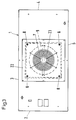
- the fan unit has a housing 1, which is advantageously cuboid.
- the housing 1 has side walls 2 to 5 which are at right angles to one another and are connected to one another by a ceiling 6.
- the side walls and the ceiling are each flat.
- the side walls 2 and 4 are each formed by profile parts which have a C-shaped cross section (FIGS. 1 and 2).
- the ceiling 6 is formed by a plate which rests on the upper edges or legs of the side walls 2 to 5 and is connected to them in a suitable manner.
- a fan element 7 is suspended from the ceiling 6. It consists of an intake nozzle 22, an impeller 7, a drive motor 10, a base plate 9 and stud bolts 8.
- the fan 7 is advantageously a radial fan with a preferably free-running wheel which has blades which are curved backwards in the direction of rotation.
- the radial fan has the advantage that it has only a very small dynamic pressure component and is highly efficient.
- the base plate 9, as shown in FIG. 1, has a square outline, is flat and is located approximately halfway up the housing 1. Seen in the axial direction of the fan 7, the plate 9 covers the fan 7 from below.
- the stud bolts 8 are provided in the corners of the plate 9.
- the drive motor 10 for the fan 7 stands on it.
- the drive motor 10 is preferred an external rotor motor. It partially projects upwards into the fan 7 (FIG. 2).
- a plate 11 extending between the side walls 3 and 5 is provided in the housing 1 and has a rectangular outline.
- the plate 11 is fastened to the side walls 3 and 5 on its two longitudinal sides.
- upwardly projecting walls 12 and 13 are provided, which extend vertically upwards from the plate 11 and end at a distance from the ceiling 6 (FIG. 2).
- the walls 12, 13 are also spaced apart from the side walls 2 and 4 of the housing 1.
- the walls 12, 13 extend between the opposite longitudinal sides 3 and 5 of the housing 1, which are formed by flat plates .
- the walls 12, 13 lie on both sides of the fan 7 at a distance from it.
- the walls 12, 13 are fastened in a suitable manner on the longitudinal sides 3, 5 of the housing 1.
- the base plate 9 of the fan 7 can also rest on the plate 11 or form a unit with it.
- the side walls 2 and 4 forming the narrow sides of the housing 1 are each formed by C-shaped profile parts. They are covered on the inside with sound-absorbing material 14, which can be mineral wool, foam and the like, for example. This sound-absorbing material 14 advantageously fills the C-profile parts completely (FIGS. 1 and 2). Between the walls 12, 13 and the sound-absorbing material 14 extending air flow channels 15 and 16 are formed over the entire width of the housing 1, through which the clean air coming from the fan 7 is guided downwards.
- the two air flow channels 15, 16 are fluidly connected via a gap 17, 18 to the central housing part 19 having the fan 7.
- the two gaps 17, 18 also extend over the entire width of the housing 1.
- a high-performance filter (not shown) is fastened to the underside of the housing 1 in a known manner and has the same cross-sectional area as the housing. The air sucked in by the fan 7 flows through this high-performance filter into the clean room located below the high-performance filter.
- the height 20 of column 17, 18, i.e. the distance between the upper edge of the walls 12, 13 and the ceiling 6 is chosen so that the flow rate in the columns 17, 18 is less than or at most equal to the flow rate in the air flow channels 15, 16. This measure ensures that only minimal pressure losses occur.
- the height of the air flow channels 15, 16 depends on the desired sound attenuation requirements. The lower the air flow channels 15, 16, the lower the sound absorption with the same width of the air flow channels. In this way, by choosing the height of the walls 12, 13 and / or by choosing the distance of the walls 12, 13 from the adjacent soundproofing layers 14, the optimum soundproofing can be set simply and inexpensively.
- the noise reduction measure takes place over the height of the unit, i.e. when flowing through the vertically arranged air flow channels 15, 16.
- the required sound damping can thus be set very easily by different heights, without thereby changing the grid dimension of the fan unit.
- different soundproofing qualities can be obtained very easily.
- the clean air emerging from the air flow channels 15, 16 hits the high-performance filter (not shown). Due to the resulting back pressure, the clean air also flows under the plate 11, so that a uniform flow distribution over the surface of the filter is achieved.
- the ceiling 6 has an installation opening into which the fan element is inserted.
- the suction nozzle 22 has a peripheral edge with which the fan element rests on the ceiling 6 along the edge of the installation opening and is fastened to it in a suitable manner.
- a protective grille 23 is provided on the suction nozzle 22.
- the sides of the sound-absorbing layers 14 facing the walls 12, 13 are flat, so that the clean air flowing through the air flow channels 15, 16 is not disturbed.
- the walls 12, 13 and the side walls 2, 4 with the sound-absorbing layers 14 are advantageously parallel to one another, so that the same flow conditions prevail over the length of the air flow channels 15, 16.
Landscapes
- Engineering & Computer Science (AREA)
- Chemical & Material Sciences (AREA)
- Combustion & Propulsion (AREA)
- Mechanical Engineering (AREA)
- General Engineering & Computer Science (AREA)
- Filtering Of Dispersed Particles In Gases (AREA)
- Structures Of Non-Positive Displacement Pumps (AREA)
- Ventilation (AREA)
Abstract
Description
- Die Erfindung betrifft eine Ventilatoreinheit für Reinräume nach dem Oberbegriff des Anspruches 1.
- Bei diesen bekannten Ventilatoreinheiten (DE-OS 42 38 595 und DE-OS 35 13 902) ist der an den Ventilator anschließende Luftströmungskanal quer zur Ventilatorachse gerichtet. Außerdem besteht der Luftströmungskanal aus zwei parallel zueinander liegenden Abschnitten, so daß die Reinluft beim Übergang vom einen Abschnitt in den anderen um 180° umgelenkt werden muß. Auf diese Weise wird die zur gewünschten Schalldämpfung erforderliche Länge des Strömungsweges der Reinluft geschaffen. Solche Ventilatoreinheiten werden in der Regel in einem Rastermaß montiert, so daß die Außenabmessungen der Ventilatoreinheit vorgegeben sind. Aus diesem Grunde kann der Strömungsweg der Reinluft quer zur Achse des Ventilators nicht beliebig groß gewählt werden. Der Schalldämpfung sind daher unter Berücksichtigung des Rastermaßes Grenzen gesetzt.
- Der Erfindung liegt die Aufgabe zugrunde, die gattungsgemäße Ventilatoreinheit so auszubilden, daß in konstruktiv einfacher und kostengünstiger Weise unter Beachtung des vorgegebenen Rastermaßes der Ventilatoreinheit eine optimale Schalldämpfung erreicht wird.
- Diese Aufgabe wird bei der gattungsgemäßen Ventilatoreinheit erfindungsgemäß mit den kennzeichnenden Merkmalen des Anspruches 1 gelöst.
- Bei der erfindungsgemäßen Ventilatoreinheit ist der Luftströmungskanal nicht in Querrichtung, sondern in Höhenrichtung ausgerichtet. Dadurch strömt die vom Ventilator angesaugte und in das Gehäuse abgegebene Reinluft im Luftströmungskanal von oben nach unten. Je nach gewünschtem Schalldämpfungsgrad kann die Höhe des Luftströmungskanales variiert werden. Das Rastermaß der Ventilatoreinheit wird dadurch aber nicht verändert, so daß unter Beibehaltung des Rastermaßes eine optimale Schalldämpfung erreicht wird.
- Weitere Merkmale der Erfindung ergeben sich aus den weiteren Ansprüchen, der Beschreibung und den Zeichnungen.
- Die Erfindung wird anhand eines in den Zeichnungen dargestellten Ausführungsbeispieles näher erläutert. Es zeigen
- Fig. 1
- eine Ansicht längs der Linie I-I in Fig. 2 einer erfindungsgemäßen Ventilatoreinheit,
- Fig. 2
- einen Querschnitt durch die erfindungsgemäße Ventilatoreinheit gemäß Fig. 1,
- Fig. 3
- eine Ansicht längs der Linie III-III in Fig. 2,
- Fig. 4
- eine Seitenansicht der erfindungsgemäßen Ventilatoreinheit.
- Die Ventilatoreinheit hat ein Gehäuse 1, das vorteilhaft quaderförmig ausgebildet ist. Das Gehäuse 1 hat rechtwinklig zueinander liegende Seitenwände 2 bis 5, die durch eine Decke 6 miteinander verbunden sind. Die Seitenwände und die Decke sind jeweils eben ausgebildet.
- Die Seitenwände 2 und 4 werden jeweils durch Profilteile gebildet, die C-förmigen Querschnitt haben (Fig. 1 und 2). Die Decke 6 wird durch eine Platte gebildet, die auf den oberen Rändern bzw. Schenkeln der Seitenwände 2 bis 5 aufliegt und in geeigneter Weise mit ihnen verbunden ist. An der Decke 6 ist ein Ventilatorelement 7 hängend befestigt. Es besteht aus einer Ansaugdüse 22, einem Laufrad 7, einem Antriebsmotor 10, einer Grundplatte 9 und aus Stehbolzen 8. Der Ventilator 7 ist vorteilhaft ein Radialventilator mit einem vorzugsweise frei laufenden Rad, das in Drehrichtung nach hinten gekrümmte Schaufeln hat. Der Radialventilator hat den Vorteil, daß er nur einen sehr kleinen dynamischen Druckanteil aufweist und einen hohen Wirkungsgrad hat.
- Die Grundplatte 9 hat, wie Fig. 1 zeigt, quadratischen Umriß, ist eben ausgebildet und befindet sich etwa in halber Höhe im Gehäuse 1. In Achsrichtung des Ventilators 7 gesehen, deckt die Platte 9 den Ventilator 7 von unten ab. Die Stehbolzen 8 sind in den Ecken der Platte 9 vorgesehen. Auf ihr steht der Antriebsmotor 10 für den Ventilator 7 auf. Der Antriebsmotor 10 ist vorzugsweise ein Außenläufermotor. Er ragt nach oben teilweise in den Ventilator 7 (Fig. 2).
- Mit Abstand unterhalb der Platte 9 ist im Gehäuse 1 eine zwischen den Seitenwänden 3 und 5 sich erstreckende Platte 11 vorgesehen, die rechteckigen Umriß hat. Die Platte 11 ist an ihren beiden Längsseiten an den Seitenwänden 3 und 5 befestigt. An den Schmalseiten der Platte 11 sind aufwärts ragende Wände 12 und 13 vorgesehen, die sich von der Platte 11 aus senkrecht aufwärts erstrecken und mit Abstand von der Decke 6 enden (Fig. 2). Die Wände 12, 13 liegen außerdem mit Abstand zu den Seitenwänden 2 und 4 des Gehäuses 1. Wie Fig. 1 zeigt, erstrecken sich die Wände 12, 13 zwischen den einander gegenüberliegenden Längsseiten 3 und 5 des Gehäuses 1, die durch ebene Platten gebildet sind. Die Wände 12, 13 liegen beiderseits des Ventilators 7 mit Abstand zu ihm. Die Wände 12, 13 sind in geeigneter Weise an den Längsseiten 3, 5 des Gehäuses 1 befestigt.
- Die Grundplatte 9 des Ventilators 7 kann auch auf der Platte 11 aufliegen oder mit ihr eine Einheit bilden.
- Die die Schmalseiten des Gehäuses 1 bildenden Seitenwände 2 und 4 sind jeweils durch C-förmige Profilteile gebildet. Sie sind innenseitig mit schalldämpfendem Material 14 bedeckt, das beispielsweise Mineralwolle, Schaumstoff und dergleichen sein kann. Dieses schalldämpfende Material 14 füllt die C-Profilteile vorteilhaft vollständig aus (Fig. 1 und 2). Zwischen den Wänden 12, 13 und dem schalldämpfenden Material 14 werden über die ganze Breite des Gehäuses 1 sich erstreckende Luftströmungskanäle 15 und 16 gebildet, durch die die vom Ventilator 7 kommende Reinluft nach unten geführt wird.
- Die beiden Luftströmungskanäle 15, 16 sind über einen Spalt 17, 18 mit dem den Ventilator 7 aufweisenden zentralen Gehäuseteil 19 strömungsverbunden. Die beiden Spalte 17, 18 erstrecken sich ebenfalls über die gesamte Breite des Gehäuses 1.
- An der Unterseite des Gehäuses 1 wird ein (nicht dargestellter) Hochleistungsfilter in bekannter Weise befestigt, der gleiche Querschnittsfläche wie das Gehäuse hat. Durch diesen Hochleistungsfilter strömt die vom Ventilator 7 angesaugte Luft in den unterhalb des Hochleistungsfilters befindlichen Reinraum.
- Die Höhe 20 der Spalte 17, 18, d.h. der Abstand zwischen dem oberen Rand der Wände 12, 13 und der Decke 6, wird so gewählt, daß die Strömungsgeschwindigkeit in den Spalten 17, 18 kleiner oder höchstens gleich der Strömungsgeschwindigkeit in den Luftströmungskanälen 15, 16 ist. Durch diese Maßnahme wird erreicht, daß nur minimale Druckverluste auftreten. Die Höhe der Luftströmungskanäle 15, 16 hängt von den gewünschten Schalldämpfungsanforderungen ab. Je niedriger die Luftströmungskanäle 15, 16 sind, desto geringer ist die Schalldämpfung bei gleicher Breite der Luftströmungskanäle. Auf diese Weise kann durch die Wahl der Höhe der Wände 12, 13 und/oder durch Wahl des Abstandes der Wände 12, 13 von den benachbarten Schalldämpfungslagen 14 die optimale Schalldämpfung einfach und kostengünstig eingestellt werden.
- Zur Erhöhung der Schalldämpfung ist es vorteilhaft, auch auf der Ober- und/oder Unterseite der Platte 11 über deren ganze Fläche ein entsprechendes schalldämpfendes Material aufzubringen.
- Bei dieser Ventilatoreinheit erfolgt die Schalldämpfungsmaßnahme über die Höhe der Einheit, d.h. beim Durchströmen der vertikal angeordneten Luftströmungskanäle 15, 16. Durch unterschiedliche Höhe läßt sich somit sehr einfach die erforderliche Schalldämpfung einstellen, ohne daß dadurch das Rastermaß der Ventilatoreinheit verändert wird. Somit können mit den beschriebenen Ventilatoreinheiten bei gleichem Rastermaß unterschiedliche Schalldämpfungsqualitäten sehr einfach erhalten werden.
- Die aus den Luftströmungskanälen 15, 16 nach unten austretende Reinluft trifft auf das (nicht dargestellte) Hochleistungsfilter. Aufgrund des hierbei entstehenden Staudruckes strömt die Reinluft auch unter die Platte 11, so daß eine gleichmäßige Strömungsverteilung über die Fläche des Filters erreicht wird.
- Zum Einbau des Ventilators 7 hat die Decke 6 eine Einbauöffnung, in welche das Ventilatorelement eingesetzt wird. Die Ansaugdüse 22 hat einen umlaufenden Rand, mit dem das Ventilatorelement längs des Randes der Einbauöffnung auf der Decke 6 aufliegt und an ihr in geeigneter Weise befestigt wird. Auf der Ansaugdüse 22 ist ein Schutzgitter 23 vorgesehen.
- Die den Wänden 12, 13 zugewandten Seiten der schalldämpfenden Lagen 14 sind eben, so daß die durch die Luftströmungskanäle 15, 16 strömende Reinluft nicht gestört wird. Die Wände 12, 13 und die Seitenwände 2, 4 mit den Schalldämpfungslagen 14 liegen vorteilhaft parallel zueinander, so daß über die Länge der Luftströmungskanäle 15, 16 gleiche Strömungsverhältnisse herrschen.
Claims (10)
- Ventilatoreinheit für Reinräume, mit einem Gehäuse, in dem mindestens ein Ventilator untergebracht ist, der mit mindestens einem Luftströmungskanal strömungsverbunden ist, in dem die Reinluft zu einem Filter strömt,
dadurch gekennzeichnet, daß der Luftströmungskanal (15, 16) in Höhenrichtung des Gehäuses (1) verläuft und sich zwischen zwei einander gegenüberliegenden Seitenwänden (3, 5) des Gehäuses (1) erstreckt, und daß wenigstens eine Seite des Luftströmungskanals (15, 16) mit schalldämpfendem Material (14) bedeckt ist. - Ventilatoreinheit nach Anspruch 1,
dadurch gekennzeichnet, daß der Luftströmungskanal (15, 16) durch wenigstens eine aufwärts, vorzugsweise senkrecht sich erstreckende Wand (12, 13) begrenzt ist, die zur Bildung einer Einströmöffnung (17, 18) mit Abstand von einer Decke (6) des Gehäuses (1) endet und vorzugsweise die beiden einander gegenüberliegenden Seitenwände (3, 5) des Gehäuses (1) miteinander verbindet. - Ventilatoreinheit nach Anspruch 1 oder 2,
dadurch gekennzeichnet, daß ein weiterer Luftströmungskanal (15, 16) vorgesehen ist, der in Höhenrichtung (1) verläuft und sich zwischen den beiden einander gegenüberliegenden Seitenwänden (3, 5) des Gehäuses (1) erstreckt, und daß vorteilhaft die beiden Luftströmungskanäle (15, 16) parallel zueinander liegen und beiderseits des Ventilators (7) liegen. - Ventilatoreinheit nach einem der Ansprüche 1 bis 3,
dadurch gekennzeichnet, daß die Luftströmungskanäle (15, 16) an einer Seite von einer Seitenwand (2, 4) des Gehäuses (1) begrenzt sind, die vorzugsweise mit dem schalldämpfenden Material (14) bedeckt sind. - Ventilatoreinheit nach einem der Ansprüche 2 bis 4,
dadurch gekennzeichnet, daß die Höhe (20) der Einströmöffnungen (17, 18) so gewählt ist, daß die Strömungsgeschwindigkeit der Reinluft beim Durchtritt durch die Einströmöffnungen (17, 18) höchstens gleich der Strömungsgeschwindigkeit in den Luftströmungskanälen (15, 16) ist. - Ventilatoreinheit nach einem der Ansprüche 1 bis 5,
dadurch gekennzeichnet, daß die den Gehäuseseitenwänden (2, 4) gegenüberliegenden Wände (12, 13) der Luftströmungskanäle (15, 16) durch einen quer, vorzugsweise senkrecht zu ihnen liegenden Boden (11) miteinander verbunden sind, der vorteilhaft mit Abstand unterhalb des Ventilators (7) liegt. - Ventilatoreinheit nach Anspruch 6,
dadurch gekennzeichnet, daß eine Grundplatte (9) des Ventilators (7) auf dem Boden (11) aufliegt. - Ventilatoreinheit nach Anspruch 6,
dadurch gekennzeichnet, daß der Boden (11) und die Grundplatte (9) des Ventilators (7) eine Einheit bilden. - Ventilatoreinheit nach einem der Ansprüche 1 bis 8,
dadurch gekennzeichnet, daß die die Luftströmungskanäle (15, 16) begrenzenden Wände (2, 4; 12, 13) parallel zueinander liegen. - Ventilatoreinheit nach einem der Ansprüche 1 bis 9,
dadurch gekennzeichnet, daß der Ventilator (7) mit einem Außenläufermotor (10) kombiniert ist.
Applications Claiming Priority (2)
| Application Number | Priority Date | Filing Date | Title |
|---|---|---|---|
| DE19511158A DE19511158C2 (de) | 1995-03-27 | 1995-03-27 | Ventilatoreinheit für Reinräume |
| DE19511158 | 1995-03-27 |
Publications (3)
| Publication Number | Publication Date |
|---|---|
| EP0735329A2 true EP0735329A2 (de) | 1996-10-02 |
| EP0735329A3 EP0735329A3 (de) | 1997-11-26 |
| EP0735329B1 EP0735329B1 (de) | 2003-02-12 |
Family
ID=7757849
Family Applications (1)
| Application Number | Title | Priority Date | Filing Date |
|---|---|---|---|
| EP96103267A Expired - Lifetime EP0735329B1 (de) | 1995-03-27 | 1996-03-02 | Ventilatoreinheit für Reinräume |
Country Status (6)
| Country | Link |
|---|---|
| US (1) | US5876279A (de) |
| EP (1) | EP0735329B1 (de) |
| KR (1) | KR100412959B1 (de) |
| CN (1) | CN1151346C (de) |
| AT (1) | ATE232591T1 (de) |
| DE (2) | DE19511158C2 (de) |
Cited By (1)
| Publication number | Priority date | Publication date | Assignee | Title |
|---|---|---|---|---|
| DE19706144C1 (de) * | 1997-02-18 | 1998-04-09 | Gebhardt Ventilatoren | Zuluftgerät, insbesondere zur Aufhängung an Decken von Reinräumen |
Families Citing this family (17)
| Publication number | Priority date | Publication date | Assignee | Title |
|---|---|---|---|---|
| US6156090A (en) * | 1997-10-03 | 2000-12-05 | Hitachi, Ltd. | Air cleaner having vanes with a winglike cross-section between a shroud and baseplate for rotation within a housing |
| KR20010113901A (ko) | 1999-04-28 | 2001-12-28 | 스트라토테크 코포레이션 | 조정 가능한 청정 공기 유동 환경 |
| DE29916321U1 (de) * | 1999-09-16 | 1999-12-23 | M + W Zander Facility Engineering GmbH + Co. KG, 70499 Stuttgart | Reinstlufteinrichtung für den Pharmazie-, Lebensmittel- und biotechnischen Bereich |
| US6383241B1 (en) | 2000-02-16 | 2002-05-07 | Battelle Memorial Institute | Protective filtration system for enclosures within buildings |
| DE10019543C2 (de) * | 2000-04-20 | 2002-03-07 | Fraunhofer Ges Forschung | Zuluftelement |
| US7137775B2 (en) * | 2003-03-20 | 2006-11-21 | Huntair Inc. | Fan array fan section in air-handling systems |
| US7597534B2 (en) * | 2003-03-20 | 2009-10-06 | Huntair, Inc. | Fan array fan section in air-handling systems |
| US11255332B2 (en) | 2003-03-20 | 2022-02-22 | Nortek Air Solutions, Llc | Modular fan housing with multiple modular units having sound attenuation for a fan array for an air-handling system |
| US7052301B2 (en) * | 2003-06-17 | 2006-05-30 | Christiana Industries, Inc. | Lamp socket |
| DE20309403U1 (de) | 2003-06-18 | 2003-08-21 | Alstom S.A., Paris | Lüfter insbesondere für einen elektrischen Schaltschrank |
| RU2303200C2 (ru) * | 2004-04-20 | 2007-07-20 | Валерий Васильевич Григорьев | Технологический блок чистых помещений |
| DE102005062523A1 (de) * | 2005-12-19 | 2007-06-21 | M+W Zander Holding Ag | Filter-Ventilator-Einheit |
| DE102006012356A1 (de) * | 2006-03-17 | 2007-09-20 | Gebhardt Ventilatoren Gmbh & Co. Kg | Ventilatoreinheit |
| JP4871714B2 (ja) * | 2006-12-07 | 2012-02-08 | エムケー精工株式会社 | 換気装置 |
| DE102008020941B4 (de) * | 2008-04-25 | 2020-09-24 | Ventomaxx Gmbh | Luftführungselement zum Zuführen und/oder Abführen von Luft |
| DE102016226157A1 (de) * | 2016-12-23 | 2018-06-28 | Ziehl-Abegg Se | Ventilatormodul sowie Anordnung eines oder mehrerer solcher Ventilatormodule in einem Strömungskanal |
| CN106949694B (zh) * | 2017-03-23 | 2020-11-03 | 苏州农业职业技术学院 | 一种用于冷库的等离子体在线杀菌装置及杀菌方法 |
Family Cites Families (8)
| Publication number | Priority date | Publication date | Assignee | Title |
|---|---|---|---|---|
| DE2138985A1 (de) * | 1971-08-04 | 1973-02-15 | Buettner Schilde Haas Ag | Belueftungseinrichtung |
| EP0147143B1 (de) * | 1983-12-16 | 1991-04-17 | Nitta Co., Ltd. | Luftreiniger |
| US4560395A (en) * | 1984-04-17 | 1985-12-24 | Environmental Air Control, Inc. | Compact blower and filter assemblies for use in clean air environments |
| ES2085499T3 (es) * | 1991-02-01 | 1996-06-01 | Meissner & Wurst | Disposicion de ventilador-filtro para su aplicacion en salas limpias. |
| DE4103026C1 (de) * | 1991-02-01 | 1992-09-10 | Meissner & Wurst Gmbh & Co, 7000 Stuttgart, De | |
| DE4122582C2 (de) * | 1991-07-08 | 1994-12-15 | Babcock Bsh Ag | Modul zum Aufbau einer Reinraumdecke |
| DK183691A (da) * | 1991-11-08 | 1993-05-09 | Novenco As | Ventilations- og filtermodul til renrumsventilation |
| DE4238595C2 (de) * | 1992-11-16 | 1996-04-11 | Kessler & Luch Gmbh | Modulare Lüftungseinheit mit integriertem Ventilator und angeschlossenem Filterrahmen, insbesondere für reinraumtechnische Zwecke |
-
1995
- 1995-03-27 DE DE19511158A patent/DE19511158C2/de not_active Expired - Fee Related
-
1996
- 1996-03-02 DE DE59610123T patent/DE59610123D1/de not_active Expired - Lifetime
- 1996-03-02 EP EP96103267A patent/EP0735329B1/de not_active Expired - Lifetime
- 1996-03-02 AT AT96103267T patent/ATE232591T1/de not_active IP Right Cessation
- 1996-03-13 CN CNB961031344A patent/CN1151346C/zh not_active Expired - Lifetime
- 1996-03-26 KR KR1019960008376A patent/KR100412959B1/ko not_active Expired - Lifetime
- 1996-03-27 US US08/624,809 patent/US5876279A/en not_active Expired - Lifetime
Cited By (2)
| Publication number | Priority date | Publication date | Assignee | Title |
|---|---|---|---|---|
| DE19706144C1 (de) * | 1997-02-18 | 1998-04-09 | Gebhardt Ventilatoren | Zuluftgerät, insbesondere zur Aufhängung an Decken von Reinräumen |
| EP0859202A2 (de) | 1997-02-18 | 1998-08-19 | GEBHARDT VENTILATOREN GMBH & CO. | Zuluftgerät, insbesondere zur Aufhängung an Decken von Reinräumen |
Also Published As
| Publication number | Publication date |
|---|---|
| CN1138156A (zh) | 1996-12-18 |
| DE59610123D1 (de) | 2003-03-20 |
| CN1151346C (zh) | 2004-05-26 |
| KR100412959B1 (ko) | 2004-03-18 |
| KR960034899A (ko) | 1996-10-24 |
| ATE232591T1 (de) | 2003-02-15 |
| US5876279A (en) | 1999-03-02 |
| EP0735329B1 (de) | 2003-02-12 |
| DE19511158A1 (de) | 1996-10-02 |
| DE19511158C2 (de) | 2000-01-27 |
| EP0735329A3 (de) | 1997-11-26 |
Similar Documents
| Publication | Publication Date | Title |
|---|---|---|
| EP0735329B1 (de) | Ventilatoreinheit für Reinräume | |
| EP1085270B1 (de) | Reinstlufteinrichtung für den Pharmazie-, Lebensmittel- und biotechnischen Bereich | |
| EP0497296B1 (de) | Filter-Ventilator-Einrichtung zur Verwendung bei Reinräumen | |
| DE3513902C2 (de) | ||
| DE3438710C2 (de) | Dachventilator | |
| DE4328995C2 (de) | Reinraumanlage | |
| DE19827449B4 (de) | Lüftereinheit für einen Luftreiniger | |
| WO2018113855A1 (de) | Ventilatormodul sowie anordnung eines oder mehrerer solcher ventilatormodule in einem strömungskanal | |
| EP3255281A1 (de) | Ventilator mit tandemnachleitschaufeln | |
| EP1053662A1 (de) | Lüfter zum anbau an ein wandelement eines schaltschrankes | |
| DE4405867C1 (de) | Bodenauslaß | |
| DE4115171C2 (de) | Ventilator-Filtereinheit für Reinraumdecken | |
| DE102012019795A1 (de) | Ventilatoreinheit | |
| EP0563509A2 (de) | Quelluftdurchlass für raumlufttechnische Anlagen | |
| DE3241860C3 (de) | Radialventilator | |
| EP0149053B1 (de) | Lüftungsvorrichtung für Räume | |
| DE4103026C1 (de) | ||
| DE4320162C2 (de) | Modul für eine Reinraumdecke | |
| EP0893655B1 (de) | Wärmestation für eine Warmluft-Kirchenheizung | |
| EP0239854B1 (de) | Luftauslass | |
| EP0609727A1 (de) | Lüftergehäuse zur Anordnung in einer Durchlassöffnung | |
| DE10019543C2 (de) | Zuluftelement | |
| CH625877A5 (en) | Method and device for conditioning products | |
| DE29704427U1 (de) | Filter-Ventilator-Einheit | |
| DE2705977A1 (de) | Belueftungseinrichtung |
Legal Events
| Date | Code | Title | Description |
|---|---|---|---|
| PUAI | Public reference made under article 153(3) epc to a published international application that has entered the european phase |
Free format text: ORIGINAL CODE: 0009012 |
|
| AK | Designated contracting states |
Kind code of ref document: A2 Designated state(s): AT BE CH DE DK ES FI FR GB GR IE IT LI LU NL PT SE |
|
| PUAL | Search report despatched |
Free format text: ORIGINAL CODE: 0009013 |
|
| AK | Designated contracting states |
Kind code of ref document: A3 Designated state(s): AT BE CH DE DK ES FI FR GB GR IE IT LI LU NL PT SE |
|
| 17P | Request for examination filed |
Effective date: 19980303 |
|
| 17Q | First examination report despatched |
Effective date: 20010430 |
|
| GRAG | Despatch of communication of intention to grant |
Free format text: ORIGINAL CODE: EPIDOS AGRA |
|
| GRAG | Despatch of communication of intention to grant |
Free format text: ORIGINAL CODE: EPIDOS AGRA |
|
| GRAH | Despatch of communication of intention to grant a patent |
Free format text: ORIGINAL CODE: EPIDOS IGRA |
|
| RAP1 | Party data changed (applicant data changed or rights of an application transferred) |
Owner name: M+W ZANDER FACILITY ENGINEERING GMBH |
|
| GRAH | Despatch of communication of intention to grant a patent |
Free format text: ORIGINAL CODE: EPIDOS IGRA |
|
| GRAA | (expected) grant |
Free format text: ORIGINAL CODE: 0009210 |
|
| AK | Designated contracting states |
Designated state(s): AT BE CH DE DK ES FI FR GB GR IE IT LI LU NL PT SE |
|
| PG25 | Lapsed in a contracting state [announced via postgrant information from national office to epo] |
Ref country code: IE Free format text: LAPSE BECAUSE OF FAILURE TO SUBMIT A TRANSLATION OF THE DESCRIPTION OR TO PAY THE FEE WITHIN THE PRESCRIBED TIME-LIMIT Effective date: 20030212 Ref country code: GR Free format text: LAPSE BECAUSE OF FAILURE TO SUBMIT A TRANSLATION OF THE DESCRIPTION OR TO PAY THE FEE WITHIN THE PRESCRIBED TIME-LIMIT Effective date: 20030212 Ref country code: FI Free format text: LAPSE BECAUSE OF FAILURE TO SUBMIT A TRANSLATION OF THE DESCRIPTION OR TO PAY THE FEE WITHIN THE PRESCRIBED TIME-LIMIT Effective date: 20030212 |
|
| REG | Reference to a national code |
Ref country code: GB Ref legal event code: FG4D Free format text: NOT ENGLISH |
|
| REG | Reference to a national code |
Ref country code: CH Ref legal event code: EP |
|
| REG | Reference to a national code |
Ref country code: CH Ref legal event code: NV Representative=s name: PATENTANWALTSBUERO JEAN HUNZIKER |
|
| PG25 | Lapsed in a contracting state [announced via postgrant information from national office to epo] |
Ref country code: LU Free format text: LAPSE BECAUSE OF NON-PAYMENT OF DUE FEES Effective date: 20030302 Ref country code: AT Free format text: LAPSE BECAUSE OF NON-PAYMENT OF DUE FEES Effective date: 20030302 |
|
| REF | Corresponds to: |
Ref document number: 59610123 Country of ref document: DE Date of ref document: 20030320 Kind code of ref document: P |
|
| PGFP | Annual fee paid to national office [announced via postgrant information from national office to epo] |
Ref country code: CH Payment date: 20030326 Year of fee payment: 8 |
|
| GBT | Gb: translation of ep patent filed (gb section 77(6)(a)/1977) |
Effective date: 20030319 |
|
| PG25 | Lapsed in a contracting state [announced via postgrant information from national office to epo] |
Ref country code: SE Free format text: LAPSE BECAUSE OF FAILURE TO SUBMIT A TRANSLATION OF THE DESCRIPTION OR TO PAY THE FEE WITHIN THE PRESCRIBED TIME-LIMIT Effective date: 20030512 Ref country code: PT Free format text: LAPSE BECAUSE OF FAILURE TO SUBMIT A TRANSLATION OF THE DESCRIPTION OR TO PAY THE FEE WITHIN THE PRESCRIBED TIME-LIMIT Effective date: 20030512 Ref country code: DK Free format text: LAPSE BECAUSE OF FAILURE TO SUBMIT A TRANSLATION OF THE DESCRIPTION OR TO PAY THE FEE WITHIN THE PRESCRIBED TIME-LIMIT Effective date: 20030512 |
|
| REG | Reference to a national code |
Ref country code: IE Ref legal event code: FG4D Free format text: GERMAN |
|
| PG25 | Lapsed in a contracting state [announced via postgrant information from national office to epo] |
Ref country code: ES Free format text: LAPSE BECAUSE OF FAILURE TO SUBMIT A TRANSLATION OF THE DESCRIPTION OR TO PAY THE FEE WITHIN THE PRESCRIBED TIME-LIMIT Effective date: 20030828 |
|
| REG | Reference to a national code |
Ref country code: IE Ref legal event code: FD4D Ref document number: 0735329E Country of ref document: IE |
|
| ET | Fr: translation filed | ||
| PLBE | No opposition filed within time limit |
Free format text: ORIGINAL CODE: 0009261 |
|
| STAA | Information on the status of an ep patent application or granted ep patent |
Free format text: STATUS: NO OPPOSITION FILED WITHIN TIME LIMIT |
|
| 26N | No opposition filed |
Effective date: 20031113 |
|
| PG25 | Lapsed in a contracting state [announced via postgrant information from national office to epo] |
Ref country code: LI Free format text: LAPSE BECAUSE OF NON-PAYMENT OF DUE FEES Effective date: 20040331 Ref country code: CH Free format text: LAPSE BECAUSE OF NON-PAYMENT OF DUE FEES Effective date: 20040331 |
|
| REG | Reference to a national code |
Ref country code: CH Ref legal event code: PL |
|
| PG25 | Lapsed in a contracting state [announced via postgrant information from national office to epo] |
Ref country code: IT Free format text: LAPSE BECAUSE OF NON-PAYMENT OF DUE FEES Effective date: 20100302 |
|
| PGRI | Patent reinstated in contracting state [announced from national office to epo] |
Ref country code: IT Effective date: 20110616 |
|
| REG | Reference to a national code |
Ref country code: DE Ref legal event code: R409 Ref document number: 59610123 Country of ref document: DE Ref country code: DE Ref legal event code: R119 Ref document number: 59610123 Country of ref document: DE |
|
| REG | Reference to a national code |
Ref country code: DE Ref legal event code: R409 Ref document number: 59610123 Country of ref document: DE |
|
| REG | Reference to a national code |
Ref country code: FR Ref legal event code: PLFP Year of fee payment: 20 |
|
| PGFP | Annual fee paid to national office [announced via postgrant information from national office to epo] |
Ref country code: IT Payment date: 20150213 Year of fee payment: 20 |
|
| PGFP | Annual fee paid to national office [announced via postgrant information from national office to epo] |
Ref country code: FR Payment date: 20150219 Year of fee payment: 20 Ref country code: GB Payment date: 20150225 Year of fee payment: 20 |
|
| PGFP | Annual fee paid to national office [announced via postgrant information from national office to epo] |
Ref country code: NL Payment date: 20150331 Year of fee payment: 20 |
|
| PGFP | Annual fee paid to national office [announced via postgrant information from national office to epo] |
Ref country code: DE Payment date: 20150525 Year of fee payment: 20 |
|
| PGFP | Annual fee paid to national office [announced via postgrant information from national office to epo] |
Ref country code: BE Payment date: 20150330 Year of fee payment: 20 |
|
| REG | Reference to a national code |
Ref country code: DE Ref legal event code: R071 Ref document number: 59610123 Country of ref document: DE Ref country code: NL Ref legal event code: MK Effective date: 20160301 |
|
| REG | Reference to a national code |
Ref country code: GB Ref legal event code: PE20 Expiry date: 20160301 |
|
| PG25 | Lapsed in a contracting state [announced via postgrant information from national office to epo] |
Ref country code: GB Free format text: LAPSE BECAUSE OF EXPIRATION OF PROTECTION Effective date: 20160301 |