EP0735376B1 - Prüfung des Widerstandes einer Metalldetektorspule - Google Patents
Prüfung des Widerstandes einer Metalldetektorspule Download PDFInfo
- Publication number
- EP0735376B1 EP0735376B1 EP96200808A EP96200808A EP0735376B1 EP 0735376 B1 EP0735376 B1 EP 0735376B1 EP 96200808 A EP96200808 A EP 96200808A EP 96200808 A EP96200808 A EP 96200808A EP 0735376 B1 EP0735376 B1 EP 0735376B1
- Authority
- EP
- European Patent Office
- Prior art keywords
- coil
- magnitude
- output signal
- signal
- detection coil
- Prior art date
- Legal status (The legal status is an assumption and is not a legal conclusion. Google has not performed a legal analysis and makes no representation as to the accuracy of the status listed.)
- Expired - Lifetime
Links
- 239000002184 metal Substances 0.000 title claims description 48
- 238000012360 testing method Methods 0.000 title claims description 46
- 238000001514 detection method Methods 0.000 claims description 66
- 238000000034 method Methods 0.000 claims description 12
- 230000001419 dependent effect Effects 0.000 claims description 9
- 230000015654 memory Effects 0.000 claims description 4
- 238000010998 test method Methods 0.000 claims description 2
- 239000000463 material Substances 0.000 description 6
- 238000012546 transfer Methods 0.000 description 4
- 238000010586 diagram Methods 0.000 description 2
- 239000004459 forage Substances 0.000 description 2
- 230000002093 peripheral effect Effects 0.000 description 2
- 230000035945 sensitivity Effects 0.000 description 2
- 241001124569 Lycaenidae Species 0.000 description 1
- 125000004122 cyclic group Chemical group 0.000 description 1
- 230000002950 deficient Effects 0.000 description 1
- 238000013461 design Methods 0.000 description 1
- 230000004907 flux Effects 0.000 description 1
- 238000003306 harvesting Methods 0.000 description 1
- 230000001939 inductive effect Effects 0.000 description 1
- 238000012986 modification Methods 0.000 description 1
- 230000004048 modification Effects 0.000 description 1
- 238000004382 potting Methods 0.000 description 1
- 230000004044 response Effects 0.000 description 1
- 230000003068 static effect Effects 0.000 description 1
- 238000006467 substitution reaction Methods 0.000 description 1
Images

Classifications
-
- G—PHYSICS
- G01—MEASURING; TESTING
- G01V—GEOPHYSICS; GRAVITATIONAL MEASUREMENTS; DETECTING MASSES OR OBJECTS; TAGS
- G01V13/00—Manufacturing, calibrating, cleaning, or repairing instruments or devices covered by groups G01V1/00 – G01V11/00
-
- G—PHYSICS
- G01—MEASURING; TESTING
- G01R—MEASURING ELECTRIC VARIABLES; MEASURING MAGNETIC VARIABLES
- G01R31/00—Arrangements for testing electric properties; Arrangements for locating electric faults; Arrangements for electrical testing characterised by what is being tested not provided for elsewhere
- G01R31/50—Testing of electric apparatus, lines, cables or components for short-circuits, continuity, leakage current or incorrect line connections
- G01R31/72—Testing of electric windings
-
- G—PHYSICS
- G01—MEASURING; TESTING
- G01V—GEOPHYSICS; GRAVITATIONAL MEASUREMENTS; DETECTING MASSES OR OBJECTS; TAGS
- G01V3/00—Electric or magnetic prospecting or detecting; Measuring magnetic field characteristics of the earth, e.g. declination, deviation
- G01V3/08—Electric or magnetic prospecting or detecting; Measuring magnetic field characteristics of the earth, e.g. declination, deviation operating with magnetic or electric fields produced or modified by objects or geological structures or by detecting devices
- G01V3/081—Electric or magnetic prospecting or detecting; Measuring magnetic field characteristics of the earth, e.g. declination, deviation operating with magnetic or electric fields produced or modified by objects or geological structures or by detecting devices the magnetic field is produced by the objects or geological structures
Definitions
- the present invention relates to a method and apparatus for testing the resistance of a coil in a metal detector of an agricultural harvesting machine, and more particularly to a testing method and apparatus which involve injecting a test signal into the coil and determining the magnitude of the output signal produced by the metal detector detection circuit connected to the coil.
- Agricultural machines such as forage harvesters are generally provided with metal detectors for detecting the presence of metal objects in crop material picked up from a field. Upon detection of a metal object the metal detector produces an output signal to stop the crop feed mechanism before the metal object can reach the cutter knives and cause damage.
- the metal detector is frequently located within a housing that is in turn located within a rotatable lower front feed roll. Crop material is picked up from a field by a pick-up mechanism and fed between lower and upper feed rolls to a cutter mechanism comprising a rotating reel having peripheral cutter knives cooperating with a stationary cutter bar to cut the crop material. Obviously, metal objects fed between the knives and the cutter bar can severely damage the cutter mechanism. The metal detector prevents such damage by sensing metal objects and, upon sensing such an object, producing an output signal which is applied to a stop mechanism to stop the feed rolls.
- the metal detector coils are located within housing and also within the feed roll, they are difficult to access. Furthermore, the coils are usually encased in a potting material and the electronic detection circuits to which the outputs of the coils are connected are also enclosed within housing as described in US-A-4,433,528, thereby making access to coil test points even more difficult.
- the resistance of the coils should be checked because changes in the resistance of a coil affects the output signal from the coil and thus the sensitivity of the metal detector to metal objects passing in proximity to the coil.
- US-A-4,639,666 is directed to an apparatus for testing a metal detector.
- This apparatus is not incorporated into the metal detector circuitry and comprises a supplementary test coil for applying a test signal to one of the detection coils of the metal detector. Further, this test apparatus is primarily intended for providing information on the sensitivity of the detector.
- Said method is characterized in that said tested electrical characteristic is the resistance of said coil and said potential differential is produced by applying a test signal to one of said ends of said coil.
- an apparatus for testing an electrical characteristic of a detection coil in a magnetic metal detector in an agricultural machine wherein the detection coil has first and second ends coupled to first and second inputs of a detector circuit which produces an output signal having a magnitude dependent on a difference in potential at said first and second inputs, said apparatus comprising:
- test signal is a varying sine wave signal, generating a varying potential differential which is transformed by the detection circuitry to output values which are monitored by the computer of the metal detection system.
- the output signal of the detector circuit may be compared with upper and lower reference signal values to check for open or shorted detector coils.
- the metal detector is located within a housing 70 that is in turn located within a rotatable lower front feed roll 72.
- Crop material 73 is picked up from a field by a pick-up mechanism (not shown) and fed between lower and upper front feed rolls 72, 71 and lower and upper rear feed rolls 76, 74 to a cutter mechanism comprising a rotating reel 78 having peripheral cutter knives 75 cooperating with a stationary cutter bar 77 to cut the crop material.
- a cutter mechanism comprising a rotating reel 78 having peripheral cutter knives 75 cooperating with a stationary cutter bar 77 to cut the crop material.
- metal objects fed between knives 75 and cutter bar 76 can severely damage the cutter mechanism.
- the metal detector prevents such damage by sensing metal objects and, upon sensing such an object, producing an output signal which is applied to a stop mechanism 98 to stop the feed rolls.
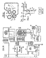
- the metal detector comprises first and second detector coils 10, 12, connected respectively to first and second channels or detection circuits 14, 16.
- coils 10, 12 are disposed in magnetic detection fields generated by suitable means (not shown) so that metal objects passing through the magnetic detection fields perturb the flux of the fields thereby inducing an emf (electromotive force) in the coils.
- the arrangement of coils 10, 12 and the means for generating the magnetic fields may, for example, be as shown in US-A-4,433,528.
- Each detection circuit includes an RFI filter section 18, a balanced resistor network 20 feeding first and second inputs 21, 23 of a differential amplifier 22, and a low pass audio filter 24.
- the ends of coil 12 are connected to inputs of the RFI filter section 18, which serves to filter out any radio frequency interference picked up by coil 12.
- the output leads 26, 28 of filter section 18 are connected to the balanced resistor network 20 which comprises four resistors R 1 , R 2 , R 3 and R 4 .
- Resistors R 1 and R 2 have equal resistances (about 1 K).
- a bias voltage V2 (+2.5 V) is connected to a junction 30 between first ends of R 1 and R 2 .
- the second ends of R 1 and R 2 are connected to leads 26, 28 at junctions 32 and 34, respectively.
- Resistors R 3 and R 4 have equal resistances (about 250 K).
- One end of resistor R 3 is connected to the first input 21 of differential amplifier 22 and the other end is connected to junction 32.
- One end of resistor R 4 is connected to the second input 23 of differential amplifier 22 and the other end is connected to junction 34.
- the detection coil 12 is located in a static magnetic detection field so that in the absence of movement of a metal object through the detection field, there is no potential difference between the ends of coil 12 and V2 determines the voltages at the inputs of differential amplifier 22 and thus the steady state output of the amplifier.
- Moving parts of the agricultural machine distort the detection field and the field is further distorted each time a tramp metal object passes through the field. As the detection field is distorted, an emf is induced in coil 12.
- the induced emf first adds to V2 at one of junctions 32, 34 and opposes V2 at the other junction as a metal object enters the detection field and then reverses polarity as the metal object leaves the detection field. This results in unequal voltages being applied to the inputs of the differential amplifier and it produces an output signal that varies about the steady state reference according to the difference in potential at inputs 21, 23.
- the output signal from differential amplifier 22 is applied to the filter 24.
- Filter 24 filters out the high frequency "noise” caused by cyclic movement of parts of the agricultural machine in the detection field.
- the filtered signal CH1 at the output of filter 24 is applied via a lead 36 to one input of a multi-channel analog to digital converter (ADC) 40 (Fig. 1B).
- ADC analog to digital converter
- ADC 40 The purpose of ADC 40 is to convert the magnitudes of the analog signals CH0 and CH1 to digital values representing the magnitudes of the signals.
- the ADC is controlled by a conventional microcomputer 42 having a CPU and RAM, ROM and E 2 PROM memories.
- a serial link 41 interconnects the microcomputer 42 and ADC 40.
- the microcomputer executes a program during which it sends signals to the ADC to enable the ADC, select one of the input channels, and transfer to the microcomputer a digital signal DATA, representing the magnitude of the output signal of the selected channel at the time the ADC is enabled.
- the ADC is controlled to sample and digitize each of the signals CH0 and CH1 every 2.5 ms.
- a positive and a negative threshold or reference value is stored in the E 2 PROM memory of the microcomputer for each of the metal detector channels.
- each digital value transferred from the ADC is compared with the positive and negative threshold values for that channel.
- the threshold values define the upper and lower limits within which the magnitude of the output signal from a respective channel will fall as long as the coil connected to the channel does not detect the passage of a tramp metal object. If a comparison shows that a value produced by ADC 40 is greater than the positive threshold value or less than (i.e.
- the microcomputer produces an output signal that is applied via serial data link 43, which may be a Controller Area Network (CAN), and a further microcomputer to the stop mechanism 98 to stop the crop feed rolls.
- serial data link 43 which may be a Controller Area Network (CAN)
- CAN Controller Area Network
- apparatus for testing the resistance of detector coils 10, 12 comprises a digital to analog converter (DAC) 44, an attenuator 46, a latch register 48 and FET switches 50 in addition to the ADC 40 and microcomputer 42.
- DAC digital to analog converter
- DAC 44 is connected to microcomputer 42 via the serial data link 41.
- the microcomputer enables DAC 44 every 2.5 ms and transfers a digital value to a holding register in the DAC.
- the DAC converts the digital value to an equivalent analog voltage which is applied over a lead 52 to attenuator 46 and a buffer 54.
- the buffer 54 is used for inductance testing of coils 10 and 12 as described in US patent application 08/414,330. Inductance testing requires a larger test signal than resistance testing and since DAC 44 is used to generate the test signal for both tests, attenuator 46 serves to reduce the magnitude of the test signal during resistance testing.
- the output of attenuator 46 is connected to inputs 1B and 4B of two FET switches 50 and the output of buffer 54 is connected to inputs 2B and 3B of two further FET switches 50. Only one of the switches is turned on at a time, the active switch being determined by which of the addressing or selection signals SW1-SW4 is active.
- the signals SW3 and SW4 enable third and fourth switches, respectively so that the output of buffer 54 is passed through the third switch to output 3A or the output of attenuator 46 is passed through the fourth switch to the output 4A.
- Outputs 3A and 4A are connected together and are further connected through a resistor 58 to a point in detector channel 0 corresponding to the junction 32 in channel 1.
- the selection signals are applied to switches 50 from the register 48.
- Register 48 is an 8-bit serial input, parallel output register with latches. The register receives data from microcomputer 42 via the serial data link 41.
- microprocessor 42 sends a code word to latch register 48 to select which detection coil 10, 12 is to receive the test signal and which test is to be performed.
- the test performed and the coil to which the test signal is applied are determined by a 1-bit in one of four bit positions of the code word as indicated in the following table: Code Word Register Output Test Performed 1000 0000 SW1 Resistance of coil 12 0100 0000 SW2 Inductance, signal applied to coil 12 0010 0000 SW3 Inductance, signal applied to coil 10 0001 0000 SW4 Resistance of coil 10
- FIG. 3 shows the equivalent circuit for the detection coil 12 and resistance network 20 when the attenuator output voltage (assumed to be larger than bias voltage V2) is applied and the detection coil is not open.
- the total current I T flowing from the attenuator through switch 50 and resistor 56 divides at junction 32 with a first portion I 1 flowing through the detection coil 12, having a resistance R C , and resistor R 2 to junction 30.
- the second part I 2 of the total current I T flows through resistor R 1 to junction 30.
- junction 34 assumes the same potential as junction 30 hence the full potential difference between junctions 32 and 30 is applied across the inputs of amplifier 22 and it produces a maximum output signal.
- the resistance of one of the detection coils 10, 12 is tested under control of a program routine executed by microcomputer 42.
- the routine may be part of a diagnostic routine called when power is turned on or when an operator initiates the routine by actuation of a control on a control panel (not shown).
- the microcomputer 42 first loads into register 48 a code word designating the detection coil whose resistance is to be tested. This causes register 48 to produce the signal SW1 if the resistance of coil 12 is to be tested or the signal SW4 if the resistance of coil 10 is to be tested. This enables one switch 50, so that the output of attenuator 46 is connected to one of the coils 10, 12.
- the microcomputer 42 stores a table of sine wave values in ROM memory and every 2.5 ms the microcomputer enables DAC 44 and transfers one of these values to a holding register in the DAC.
- the DAC converts the sine wave values to an output voltage which is applied through the attenuator 46 and switch 50 to the designated detection coil 10, 12. Assuming the output of the attenuator is applied to detection coil 12 channel 1 produces an output signal CH1 on lead 36 having a magnitude dependent on the resistance of coil 12.
- the microcomputer 42 then turns ADC 40 on and every 2.5 ms transfers from the ADC to the microcomputer the digital signals produced by the ADC and representing the magnitude of the signal on lead 36.
- a peak detector 66 and a comparator 68 are implemented by programming in the microcomputer 42.
- the peak detector detects the peak positive value of the values received from ADC 40.
- the ROM in the microcomputer holds first and second threshold or reference signal values representing a maximum magnitude and a minimum magnitude, respectively, that an output signal on lead 36 or 38 may have when the resistance of coil 10 or coil 12 is within an acceptable range.
- the magnitude of the test signal injected into the detection circuits is known and from the design and configuration of the detection circuits and detection coils the magnitudes of the output signals from the detection circuits may be calculated.
- the reference signal values are offset above and below the calculated magnitude depending on how much variation in coil resistance may be tolerated.
- the microcomputer 42 compares the positive peak value produced by the peak detector 66 with each of the reference signal values. If the comparison indicates that the peak value derived from the ADC signals has a magnitude greater than the reference maximum magnitude or less than the reference minimum magnitude, then the resistance of the coil being tested is outside the acceptable range. In this case the microcomputer sends to a display 60, via the serial data link 43 and microcomputer 45, a code indicating that a coil is defective.
- the resistance of coil 10 is tested in a similar manner except that register 48 is loaded with the code 0001 0000 and the microcomputer controls ADC 40 to sample the resulting detector output signal CH0 on lead 38.
- the signal injected into the coil being tested is a sine wave.
- the frequency of this sine wave is quite low so that the signal produced at the output of the differential amplifier will pass through the low pass filter 24.
- test signal need not be a sine wave signal although a sine wave is preferred.
- the invention is not limited to use with the specific metal detector described herein but may be used with many types of metal detectors.
Landscapes
- Engineering & Computer Science (AREA)
- Physics & Mathematics (AREA)
- Life Sciences & Earth Sciences (AREA)
- General Physics & Mathematics (AREA)
- Remote Sensing (AREA)
- General Life Sciences & Earth Sciences (AREA)
- Geophysics (AREA)
- Electromagnetism (AREA)
- Power Engineering (AREA)
- Environmental & Geological Engineering (AREA)
- Geology (AREA)
- Manufacturing & Machinery (AREA)
- Geophysics And Detection Of Objects (AREA)
- Measurement Of Resistance Or Impedance (AREA)
Claims (14)
- Verfahren zum Prüfen einer elektrischen Charakteristik (Rc) einer Detektionswicklung (12) in einem magnetischen Metalldetektor in einer landwirtschaftlichen Maschine, bei dem die Detektionswicklung (12) erste und zweite Enden aufweist, die mit ersten und zweiten Eingängen einer Detektorschaltung (16) verbunden sind, die ein Ausgangssignal (CH1) erzeugt, das eine Amplitude aufweist, die von einer Differenz des Potentials an den ersten und zweiten Eingängen abhängt, wobei das Verfahren folgendes umfasst:wobei das Verfahren dadurch gekennzeichnet ist, dass:Erzeugen einer Potential-Differenz, die von der Charakteristik (Rc) der Wicklung abhängt längs der Wicklung (12) und längs der ersten und zweiten Eingänge;während der Erzeugung der Potential-Differenz, Vergleichen der Amplitude des Ausgangssignals (CH1), das von der Detektorschaltung (16) erzeugt wird, mit einem ersten Bezugssignalwert, der eine Amplitude darstellt, die das Ausgangssignal (CH1) haben kann, wenn die Charakteristik (Rc) der Detektionswicklung (12) innerhalb eines normalen Bereiches liegt; undErzeugen einer Anzeige, dass die Charakteristik (Rc) der Detektionswicklung (12) außerhalb des normalen Bereiches liegt, wenn die Amplitude des Ausgangssignals (CH1) den ersten Bezugssignalwert übersteigt,die geprüfte elektrische Charakteristik der Widerstand (Rc) der Wicklung (12) ist; unddie Potential-Differenz durch Anlegen eines Testsignals an einer der Enden der Wicklung (12) erzeugt wird.
- Verfahren nach Anspruch 1, dadurch gekennzeichnet, dass:der erste Bezugssignalwert eine maximale Amplitude darstellt, den das Ausgangssignal (CH1) haben kann, wenn sich der Widerstand (Rc) innerhalb eines normalen Bereiches befindet; unddas Verfahren die weiteren folgenden Schritte umfasst:während das Testsignal angelegt wird, Vergleichen der Amplitude des Ausgangssignals (CH1) mit einem zweiten Bezugssignalwert, der eine minimale Amplitude darstellt, die das Ausgangssignal (CH1) haben darf, wenn der Widerstand (Rc) innerhalb eines normalen Bereiches liegt; undErzeugen einer Anzeige, dass der Widerstand (Rc) außerhalb des normalen Bereiches liegt, wenn die Amplitude des Ausgangssignals (CH1) kleiner als der zweite Bezugssignalwert ist.
- Verfahren nach Anspruch 1 oder Anspruch 2, dadurch gekennzeichnet, dass das Testsignal ein sich änderndes Sinusschwingungssignal ist.
- Verfahren nach Anspruch 3 unter Rückbeziehung auf Anspruch 2, dadurch gekennzeichnet, dass der Vergleich der Amplitude des Ausgangssignals (CH1) mit den ersten und zweiten Bezugssignalwerten folgendes umfasst:Umwandeln des Ausgangssignals (CH1) in Digitalwerte (DATA), die die Amplitude des Ausgangssignals (CH1) darstellen, wenn sich das Sinusschwingungssignal ändert; undVergleichen der digitalen Werte (DATA) mit digitalen Werten, die die ersten und zweiten Bezugssignalwerte darstellen.
- Verfahren nach einem der vorhergehenden Ansprüche, dadurch gekennzeichnet, dass der magnetische Metalldetektor folgendes umfasst:wobei ein zweites Ende des ersten Widerstandes (R1) mit einem ersten Ende der Detektionswicklung (12) und einem ersten Eingang (21) der Differenzverstärkereinrichtung (22) verbunden ist, undein symmetrisches Widerstandsnetzwerk (20), das erste und zweite Widerstände (R1, R2) und eine Vorspannungsquelle (V2) einschließt, die mit einem ersten Ende der ersten und zweiten Widerstände (R1, R2) verbunden ist; undDifferenzverstärkereinrichtungen (22),
ein zweites Ende des zweiten Widerstandes (R2) mit einem zweiten Ende der Detektionswicklung (12) und einem zweiten Eingang (23) der Differenzverstärkereinrichtung (22) verbunden ist;
wobei das Verfahren weiterhin dadurch gekennzeichnet ist, dass:das Testsignal an einem Punkt (32) zwischen einem zweiten Ende eines der ersten und zweiten Widerstände (R1, R2) und einem Ende der Detektionswicklung(12) zugeführt wird. - Vorrichtung zum Prüfen einer elektrischen Eigenschaft (Rc) einer Detektionswicklung (12) in einem magnetischen Metalldetektor in einer landwirtschaftlichen Maschine, wobei die Detektionswicklung (12) erste und zweite Enden aufweist, die mit ersten und zweiten Eingängen einer Detektorschaltung (16) verbunden sind, die ein Ausgangssignal (CH1) erzeugt, das eine Größe aufweist, die von einer Differenz des Potentials an den ersten und zweiten Enden abhängt,
wobei die Vorrichtung folgendes umfasst:wobei die Vorrichtung dadurch gekennzeichnet ist, dass:Einrichtungen (42, 44, 46, 50) zur Erzeugung einer Potential-Differenz, die von der Charakteristik (Rc) der Wicklung abhängt, längs der Wicklung (12) und den ersten und zweiten Eingängen;Einrichtungen (40, 42), die während der Erzeugung der Potential-Differenz betrieben werden, um die Amplitude des von der Detektorschaltung (16) erzeugten Ausgangssignals (CH1) mit einem ersten Bezugssignalwert zu vergleichen, der eine Amplitude darstellt, die das Ausgangssignal haben kann, wenn die Charakteristik (Rc) der Detektionswicklung innerhalb eines normalen Bereiches liegt; undEinrichtungen (42) zur Erzeugung einer Anzeige dafür, dass die Charakteristik der Detektionswicklung (12) außerhalb des normalen Bereiches liegt, wenn die Amplitude des Ausgangssignals (CH1) den ersten Bezugssignalwert übersteigt;die geprüfte elektrische Charakteristik der Widerstand (Rc) der Wicklung (12) ist; unddie Einrichtungen (42, 44, 46, 50) zur Erzeugung der Potential-Differenz ein Testsignal an eines der Enden der Wicklung (12) anlegen. - Vorrichtung nach Anspruch 6, dadurch gekennzeichnet, dass das Testsignal ein sich änderndes Sinusschwingungssignal ist.
- Vorrichtung nach Anspruch 6 oder 7, dadurch gekennzeichnet, dass:wobei während der Zuführung des Testsignals die Einrichtungen (40, 42) zum Vergleichen der Amplitude des Ausgangssignals (CH1) die Amplitude mit einem zweiten Bezugssignalwert vergleichen, der eine minimale Amplitude darstellt, die das Ausgangssignal (CH1) haben kann, wenn der Widerstand (Rc) innerhalb eines normalen Bereiches liegt; undder erste Bezugssignalwert eine maximale Amplitude darstellt, die das Ausgangssignal (CH1) haben kann, wenn der Widerstand (Rc) innerhalb eines normalen Bereiches liegt;
wobei die Einrichtungen (42) zur Erzeugung einer Anzeige eine Anzeige erzeugen, dass der Widerstand (Rc) außerhalb des normalen Bereiches liegt, wenn die Amplitude des Ausgangssignals (CH1) kleiner als der zweite Bezugssignalwert ist. - Vorrichtung nach einem der Ansprüche 6 bis 8, dadurch gekennzeichnet, dass die Einrichtungen (42, 44, 46, 50) zur Erzeugung der Potential-Differenz einen Mikrocomputer (42) zur Lieferung von digitalen Werten (DATA) an einen Digital/Analog-Wandler (44) zur Erzeugung des Testsignals und Einrichtungen (50) zur Verbindung des Digital-/Analog-Wandlers (44) mit der Detektionswicklung (12) einschließen.
- Vorrichtung nach Anspruch 8, dadurch gekennzeichnet, dass die Einrichtung zum Vergleichen (40, 42) folgendes einschließt:einen Analog-/Digital-Wandler (40), der auf das Ausgangssignal (CH1) von der Detektionsschaltung (16) anspricht, um digitale Werte (DATA) zu erzeugen, die die Amplitude des Ausgangssignals (CH1) darstellen; undeinen Mikrocomputer (42), der Speichereinrichtungen (E2PROM) zum Speichern der ersten und zweiten Bezugssignalwerte und Einrichtungen (VERGLEICH) zum Vergleich der digitalen Werte mit den ersten und zweiten Bezugssignalwerten einschließt.
- Vorrichtung nach Anspruch 7, dadurch gekennzeichnet, dass die Einrichtungen (42, 44, 46, 50) zur Erzeugung einer Potential-Differenz folgendes einschließen:einen Digital-/Analog-Wandler (44) mit einem Ausgang, der mit der Detektionswicklung (12) verbunden ist;Einrichtungen (ROM) zum Speichern einer Tabelle von Werten, die eine Sinusschwingung darstellen; undEinrichtungen (42) zur Zuführung eines Wertes zu einer Zeit von der Tabelle von Werten an den Digital-/Analog-Wandler (44), um ein Sinusschwingungssignal an die Detektionswicklung (12) anzulegen.
- Vorrichtung nach einem der Ansprüche 6 bis 11, dadurch gekennzeichnet, dass die Einrichtung zum Vergleichen (40, 42) einen Spitzenwertdetektor (SPITZENWERT) zur Erfassung eines Spitzenwertes aus den digitalen Werten (DATA) und einen Vergleicher (VERGLEICH) zum Vergleichen des Spitzenwertes mit dem ersten Bezugssignalwert umfasst.
- Vorrichtung nach einem der Ansprüche 6 bis 12, dadurch gekennzeichnet, dass der magnetische Metalldetektor folgendes umfasst:wobei eine zweites Ende des ersten Widerstandes (R1) mit einem ersten Ende der Detektionswicklung (12) und einem ersten Eingang (21) der Differenzverstärkereinrichtung (22) gekoppelt ist, undein symmetrisches Widerstandsnetzwerk (20), das erste und zweite Widerstände (R1, R2) und eine Vorspannungsquelle V2 einschließt, die mit einem ersten Ende der ersten und zweiten Widerstände (R1, R2) verbunden ist; undDifferenzverstärkereinrichtungen (22),
wobei ein zweites Ende des zweiten Widerstandes (R2) mit einem zweiten Ende der Detektionswicklung (12) und einem zweiten Eingang (23) der Differenzverstärkereinrichtung (22) gekoppelt ist;
wobei die Einrichtungen (42, 44, 46, 50) zur Erzeugung der Potential-Differenz das Testsignal an einem Punkt (32) zwischen einem zweiten Ende eines der ersten und zweiten Widerstände (R1, R2) und einem Ende der Detektionswicklung (12) anlegen. - Vorrichtung nach einem der Ansprüche 6 bis 13, dadurch gekennzeichnet, dass der magnetische Metalldetektor eine zweite Detektionswicklung (10) mit Enden aufweist, die mit Eingängen einer zweiten Detektionsschaltung (14) gekoppelt sind, die ein zweites Ausgangssignal (CH0) erzeugt, wobei die Vorrichtung weiterhin folgendes umfasst:Schaltereinrichtungen (50) zum selektiven Verbinden der Einrichtungen (42,44, 46) zur Erzeugung einer Potential-Differenz mit der zweiten Wicklung (10) zum Anlegen eines Testsignals an eines der Enden der zweiten Wicklung (10); undEinrichtungen (40, 42), die während des Anlegens des Testsignals an die zweite Wicklung (10) betreibbar sind, um zu bestimmen, ob die Amplitude eines Ausgangssignals (CH1), das von der zweiten Detektionsschaltung (14) erzeugt wird, in einen vorgegebenen Bereich von Amplituden fällt.
Applications Claiming Priority (2)
| Application Number | Priority Date | Filing Date | Title |
|---|---|---|---|
| US08/414,788 US5627475A (en) | 1995-03-31 | 1995-03-31 | Metal detector coil resistance testing |
| US414788 | 1995-03-31 |
Publications (3)
| Publication Number | Publication Date |
|---|---|
| EP0735376A2 EP0735376A2 (de) | 1996-10-02 |
| EP0735376A3 EP0735376A3 (de) | 1997-07-23 |
| EP0735376B1 true EP0735376B1 (de) | 2003-11-05 |
Family
ID=23642969
Family Applications (1)
| Application Number | Title | Priority Date | Filing Date |
|---|---|---|---|
| EP96200808A Expired - Lifetime EP0735376B1 (de) | 1995-03-31 | 1996-03-26 | Prüfung des Widerstandes einer Metalldetektorspule |
Country Status (3)
| Country | Link |
|---|---|
| US (1) | US5627475A (de) |
| EP (1) | EP0735376B1 (de) |
| DE (1) | DE69630553T2 (de) |
Families Citing this family (15)
| Publication number | Priority date | Publication date | Assignee | Title |
|---|---|---|---|---|
| GB2309308B (en) * | 1996-01-17 | 2000-12-06 | Abb Kent Taylor Ltd | Calibration of flow meters |
| DE19620526A1 (de) * | 1996-05-22 | 1997-11-27 | Burkhard Weis | Metalldetektor zum Erkennen von Metall im Erntegutfluß |
| GB2315657A (en) * | 1996-07-30 | 1998-02-11 | Ford New Holland Nv | Harvesting machines,protective arrangements |
| DE29805631U1 (de) * | 1998-03-27 | 1998-06-25 | Ebinger, Klaus, 51149 Köln | Magnetometer |
| US6794883B2 (en) * | 2002-03-19 | 2004-09-21 | Emerson Electric Co. | Method and system for monitoring winding insulation resistance |
| DE10325252A1 (de) * | 2003-06-03 | 2004-12-23 | Claas Saulgau Gmbh | Landmaschine |
| US7227441B2 (en) * | 2005-02-04 | 2007-06-05 | Schweitzer Engineering Laboratories, Inc. | Precision Rogowski coil and method for manufacturing same |
| US7227442B2 (en) * | 2005-04-01 | 2007-06-05 | Schweitzer Engineering Laboratories, Inc. | Precision printed circuit board based rogowski coil and method for manufacturing same |
| US7545138B2 (en) * | 2006-07-06 | 2009-06-09 | Schweitzer Engineering Laboratories, Inc. | Precision, temperature-compensated, shielded current measurement device |
| US7812665B2 (en) * | 2009-02-23 | 2010-10-12 | Number 14 B.V. | Amplifiers with input offset trim and methods |
| US8928337B2 (en) | 2012-01-27 | 2015-01-06 | Schweitzer Engineering Laboratories, Inc. | Device for measuring electrical current and method of manufacturing the same |
| GB2523326B (en) | 2014-02-19 | 2017-11-29 | Vivax-Metrotech Ltd | Detection apparatus with self-test function |
| CN110927822B (zh) * | 2019-12-03 | 2021-05-18 | 吉林大学 | 一种评估希尔伯特变换算法获得磁梯度张量准确性的方法 |
| US11617269B2 (en) | 2021-07-20 | 2023-03-28 | Schweitzer Engineering Laboratories, Inc. | Current measuring device for an electric power protection system |
| US12504446B2 (en) | 2023-12-19 | 2025-12-23 | Schweitzer Engineering Laboratories, Inc. | Fault current sensor with adjacent phase fault immunity |
Family Cites Families (4)
| Publication number | Priority date | Publication date | Assignee | Title |
|---|---|---|---|---|
| US4084135A (en) * | 1975-08-25 | 1978-04-11 | The Goodyear Tire & Rubber Company | System and method for checking the sensitivity and performance of an electromagnetic field variation detector |
| US4746869A (en) * | 1987-06-10 | 1988-05-24 | Hesston Corporation | Circuit for testing inductive coils |
| FI882966A7 (fi) * | 1987-07-31 | 1989-02-01 | Siemens Ag | Foerfarande foer lindningsresistansmaetning av en med en stroemriktare matad vaexel- eller vridstroemsmaskin under bruk. |
| US5111149A (en) * | 1989-02-28 | 1992-05-05 | Baker Electrical Instrument Company | Method and apparatus for automatically calculating the integrity of an electrical coil |
-
1995
- 1995-03-31 US US08/414,788 patent/US5627475A/en not_active Expired - Lifetime
-
1996
- 1996-03-26 EP EP96200808A patent/EP0735376B1/de not_active Expired - Lifetime
- 1996-03-26 DE DE69630553T patent/DE69630553T2/de not_active Expired - Lifetime
Also Published As
| Publication number | Publication date |
|---|---|
| EP0735376A2 (de) | 1996-10-02 |
| EP0735376A3 (de) | 1997-07-23 |
| DE69630553T2 (de) | 2004-05-13 |
| US5627475A (en) | 1997-05-06 |
| DE69630553D1 (de) | 2003-12-11 |
Similar Documents
| Publication | Publication Date | Title |
|---|---|---|
| EP0735376B1 (de) | Prüfung des Widerstandes einer Metalldetektorspule | |
| US5677634A (en) | Apparatus for stress testing capacitive components | |
| DE10131229B4 (de) | Eine physikalische Größe erfassender Sensor | |
| EP0358483B1 (de) | Automatischer Felderdungsdetektor und Lokalisator | |
| US5921939A (en) | Device for monitoring measurement electrodes to detect the presence of faults in electrode, leads and in the connection of the electrodes to a patient | |
| CA1277002C (en) | Coin detection means and method | |
| US6025711A (en) | Sensor circuit with diagnostic capability | |
| US5963038A (en) | Method of testing a connection which includes a conductor in an integrated circuit | |
| US5789934A (en) | Test circuit including a power supply with a current transformer to monitor capacitor output current | |
| US4746869A (en) | Circuit for testing inductive coils | |
| US6429641B1 (en) | Power booster and current measuring unit | |
| US4837502A (en) | Computer-aided, logic pulsing probe for locating faulty circuits on a printed circuit card | |
| DE69203007T2 (de) | Vorrichtung zur Fehleridentifizierung in Fahrzeuginsassen-Schutzsystemen. | |
| EP0735377B1 (de) | Prüfung der Induktion von Metalldetektorspulen | |
| US5644236A (en) | Method and apparatus for simultaneously testing the inductance of detection coils in a multiple channel metal detector | |
| US4590472A (en) | Analog signal conditioner for thermal coupled signals | |
| US5903160A (en) | Method and apparatus for testing an electrical conductor assembly | |
| US6657452B2 (en) | Configuration for measurement of internal voltages of an integrated semiconductor apparatus | |
| US6011476A (en) | Metering circuit to detect dielectrokinetic response | |
| US6598182B1 (en) | Electromigration and extrusion monitor and control system | |
| WO1997046891A1 (en) | Method of testing a connection which includes a conductor in an integrated circuit | |
| US4382227A (en) | Multipurpose test equipment input circuitry | |
| US11333685B1 (en) | Functional safety of measurements | |
| JP3183051B2 (ja) | センサ用短絡検出器 | |
| EP0366453A2 (de) | Variabler Strom-Spannungs-Verstärker mit einem verstärkungsunabhängigen Prüfungsmodus |
Legal Events
| Date | Code | Title | Description |
|---|---|---|---|
| PUAI | Public reference made under article 153(3) epc to a published international application that has entered the european phase |
Free format text: ORIGINAL CODE: 0009012 |
|
| AK | Designated contracting states |
Kind code of ref document: A2 Designated state(s): DE FR GB |
|
| PUAL | Search report despatched |
Free format text: ORIGINAL CODE: 0009013 |
|
| AK | Designated contracting states |
Kind code of ref document: A3 Designated state(s): DE FR GB |
|
| 17P | Request for examination filed |
Effective date: 19980116 |
|
| RAP1 | Party data changed (applicant data changed or rights of an application transferred) |
Owner name: CNH BELGIUM N.V. |
|
| GRAH | Despatch of communication of intention to grant a patent |
Free format text: ORIGINAL CODE: EPIDOS IGRA |
|
| GRAA | (expected) grant |
Free format text: ORIGINAL CODE: 0009210 |
|
| GRAS | Grant fee paid |
Free format text: ORIGINAL CODE: EPIDOSNIGR3 |
|
| AK | Designated contracting states |
Kind code of ref document: B1 Designated state(s): DE FR GB |
|
| REG | Reference to a national code |
Ref country code: GB Ref legal event code: FG4D |
|
| REF | Corresponds to: |
Ref document number: 69630553 Country of ref document: DE Date of ref document: 20031211 Kind code of ref document: P |
|
| ET | Fr: translation filed | ||
| PLBE | No opposition filed within time limit |
Free format text: ORIGINAL CODE: 0009261 |
|
| STAA | Information on the status of an ep patent application or granted ep patent |
Free format text: STATUS: NO OPPOSITION FILED WITHIN TIME LIMIT |
|
| 26N | No opposition filed |
Effective date: 20040806 |
|
| PGFP | Annual fee paid to national office [announced via postgrant information from national office to epo] |
Ref country code: DE Payment date: 20140118 Year of fee payment: 19 |
|
| REG | Reference to a national code |
Ref country code: DE Ref legal event code: R082 Ref document number: 69630553 Country of ref document: DE Representative=s name: G. KOCH UND KOLLEGEN, DE |
|
| PGFP | Annual fee paid to national office [announced via postgrant information from national office to epo] |
Ref country code: FR Payment date: 20140115 Year of fee payment: 19 |
|
| REG | Reference to a national code |
Ref country code: DE Ref legal event code: R082 Ref document number: 69630553 Country of ref document: DE Representative=s name: G. KOCH UND KOLLEGEN, DE Effective date: 20140519 Ref country code: DE Ref legal event code: R081 Ref document number: 69630553 Country of ref document: DE Owner name: CNH INDUSTRIAL BELGIUM NV, BE Free format text: FORMER OWNER: CNH BELGIUM NV, ZEDELGEM, BE Effective date: 20140519 |
|
| PGFP | Annual fee paid to national office [announced via postgrant information from national office to epo] |
Ref country code: GB Payment date: 20140120 Year of fee payment: 19 |
|
| REG | Reference to a national code |
Ref country code: FR Ref legal event code: CD Owner name: CNH INDUSTRIAL BELGIUM NV Effective date: 20140725 |
|
| REG | Reference to a national code |
Ref country code: DE Ref legal event code: R119 Ref document number: 69630553 Country of ref document: DE |
|
| GBPC | Gb: european patent ceased through non-payment of renewal fee |
Effective date: 20150326 |
|
| REG | Reference to a national code |
Ref country code: FR Ref legal event code: ST Effective date: 20151130 |
|
| PG25 | Lapsed in a contracting state [announced via postgrant information from national office to epo] |
Ref country code: GB Free format text: LAPSE BECAUSE OF NON-PAYMENT OF DUE FEES Effective date: 20150326 Ref country code: DE Free format text: LAPSE BECAUSE OF NON-PAYMENT OF DUE FEES Effective date: 20151001 |
|
| PG25 | Lapsed in a contracting state [announced via postgrant information from national office to epo] |
Ref country code: FR Free format text: LAPSE BECAUSE OF NON-PAYMENT OF DUE FEES Effective date: 20150331 |