EP0735392A1 - Connection system between a printed board and a cable and bush for use in said connection system - Google Patents
Connection system between a printed board and a cable and bush for use in said connection system Download PDFInfo
- Publication number
- EP0735392A1 EP0735392A1 EP96104296A EP96104296A EP0735392A1 EP 0735392 A1 EP0735392 A1 EP 0735392A1 EP 96104296 A EP96104296 A EP 96104296A EP 96104296 A EP96104296 A EP 96104296A EP 0735392 A1 EP0735392 A1 EP 0735392A1
- Authority
- EP
- European Patent Office
- Prior art keywords
- bush
- panel
- connection system
- connection means
- connection
- Prior art date
- Legal status (The legal status is an assumption and is not a legal conclusion. Google has not performed a legal analysis and makes no representation as to the accuracy of the status listed.)
- Withdrawn
Links
- 239000002184 metal Substances 0.000 claims description 2
- 239000000835 fiber Substances 0.000 abstract description 14
- 238000003780 insertion Methods 0.000 description 2
- 230000037431 insertion Effects 0.000 description 2
- 238000004519 manufacturing process Methods 0.000 description 2
- 238000011084 recovery Methods 0.000 description 2
- 230000009471 action Effects 0.000 description 1
- 230000008901 benefit Effects 0.000 description 1
- 230000008878 coupling Effects 0.000 description 1
- 238000010168 coupling process Methods 0.000 description 1
- 238000005859 coupling reaction Methods 0.000 description 1
- 230000007812 deficiency Effects 0.000 description 1
- 230000001419 dependent effect Effects 0.000 description 1
- 239000006185 dispersion Substances 0.000 description 1
- 239000000463 material Substances 0.000 description 1
- 230000004048 modification Effects 0.000 description 1
- 238000012986 modification Methods 0.000 description 1
- 230000003287 optical effect Effects 0.000 description 1
- 239000013307 optical fiber Substances 0.000 description 1
- 230000007704 transition Effects 0.000 description 1
Images


Classifications
-
- G—PHYSICS
- G02—OPTICS
- G02B—OPTICAL ELEMENTS, SYSTEMS OR APPARATUS
- G02B6/00—Light guides; Structural details of arrangements comprising light guides and other optical elements, e.g. couplings
- G02B6/24—Coupling light guides
- G02B6/36—Mechanical coupling means
- G02B6/38—Mechanical coupling means having fibre to fibre mating means
- G02B6/3807—Dismountable connectors, i.e. comprising plugs
- G02B6/3897—Connectors fixed to housings, casing, frames or circuit boards
-
- G—PHYSICS
- G02—OPTICS
- G02B—OPTICAL ELEMENTS, SYSTEMS OR APPARATUS
- G02B6/00—Light guides; Structural details of arrangements comprising light guides and other optical elements, e.g. couplings
- G02B6/24—Coupling light guides
- G02B6/36—Mechanical coupling means
- G02B6/38—Mechanical coupling means having fibre to fibre mating means
- G02B6/3807—Dismountable connectors, i.e. comprising plugs
- G02B6/381—Dismountable connectors, i.e. comprising plugs of the ferrule type, e.g. fibre ends embedded in ferrules, connecting a pair of fibres
- G02B6/3817—Dismountable connectors, i.e. comprising plugs of the ferrule type, e.g. fibre ends embedded in ferrules, connecting a pair of fibres containing optical and electrical conductors
-
- H—ELECTRICITY
- H01—ELECTRIC ELEMENTS
- H01R—ELECTRICALLY-CONDUCTIVE CONNECTIONS; STRUCTURAL ASSOCIATIONS OF A PLURALITY OF MUTUALLY-INSULATED ELECTRICAL CONNECTING ELEMENTS; COUPLING DEVICES; CURRENT COLLECTORS
- H01R13/00—Details of coupling devices of the kinds covered by groups H01R12/70 or H01R24/00 - H01R33/00
- H01R13/73—Means for mounting coupling parts to apparatus or structures, e.g. to a wall
- H01R13/74—Means for mounting coupling parts in openings of a panel
-
- G—PHYSICS
- G02—OPTICS
- G02B—OPTICAL ELEMENTS, SYSTEMS OR APPARATUS
- G02B6/00—Light guides; Structural details of arrangements comprising light guides and other optical elements, e.g. couplings
- G02B6/24—Coupling light guides
- G02B6/36—Mechanical coupling means
- G02B6/38—Mechanical coupling means having fibre to fibre mating means
- G02B6/3807—Dismountable connectors, i.e. comprising plugs
- G02B6/381—Dismountable connectors, i.e. comprising plugs of the ferrule type, e.g. fibre ends embedded in ferrules, connecting a pair of fibres
- G02B6/3825—Dismountable connectors, i.e. comprising plugs of the ferrule type, e.g. fibre ends embedded in ferrules, connecting a pair of fibres with an intermediate part, e.g. adapter, receptacle, linking two plugs
Definitions
- the invention relates to a connection system between a printed board and a cable, in particular a fiber optic cable, having a connector connectable by rotation and to a bush for use in said connection system.
- the printed boards have a connection system on their back side. When they are plugged in an apparatus they are connected to respective back panels through suitable connectors so as to allow the electrical connection between all the printed boards of the apparatus. Often, for various reasons, additional systems are necessary for connecting to cables, which are usually located near the front side of the boards, such as, e.g., connections to fiber optic cables.
- connection system is also known for fiber optic cables on the back portion of the printed board. Such connection is carried out through snap action connectors of the type SC-PC in such a way that, when the board is drawn out, such connectors break loose releasing it.
- connectors connectable by rotation of the screw-in type or the like such as, e.g., the FC-PC connectors, which allow a better axial alignment between the two fiber optic cables and therefore a lower dispersion and attenuation of the transmitted light signal are used.
- Another object of the present invention is so to provide a system of the type mentioned at the outset as to be easy to manufacture and at low cost.
- connection system having the features as set forth in claim 1 and a bush to be used in this system having the features set forth in claim 6.
- connection system according to the invention is characterized in that the draw-out stress transmitted by the printed board to the connectors is shifted on the back-panel thus preventing the connector from sliding axially and therefore pulling and destroying the fiber optic cables if the connectors are not disconnected in advance.
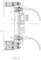
- Fig. 1 shows a detail of the electrical connection between a printed board 7 and a back-panel 2 through a conventional electrical connector 8. Further, connections are provided with fiber optic cables 5 (two in the embodiment illustrated in Fig. 1) realized by connection systems in accordance with the present invention.
- Fiber optic cables 5 are provided with respective connectors 1 connectable by rotation such as, e.g., the so-called FC-PC connectors. They are connectable to corresponding connectors 3 type socket SM, fixedly mounted on the back portion of the printed board 7 and acting as a transition for further connections.
- connectors 1 connectable by rotation such as, e.g., the so-called FC-PC connectors. They are connectable to corresponding connectors 3 type socket SM, fixedly mounted on the back portion of the printed board 7 and acting as a transition for further connections.
- connection is carried out through corresponding holes drilled on the back-panel 2.
- connection bush 4 fixedly connected with the back-panel 2 designed to transmit to the back-panel 2 the draw-out stress exerted by the printed board 7 on connector 1 of the fiber optic cable 5 through the connector 3, when connectors 1 and 3 are screwed each other.
- bush 4 is snapped into the corresponding hole provided on back-panel 2 to allow connection of connectors 1 and 3.
- a resilient body made of plastic or metal having substantially the shape of a hollow cylinder with its front face 13 in the form of an annulus abutting on the flange of connector 3 (see Fig. 2) and its rear face 14 in the form of an annulus too.
- an external chamfer 12 making an angle of 45° with the axis of the cylinder whose function is to easy the insertion of the bush into the corresponding hole of the back panel 2.
- An internal chamfer 15 making an angle of 60° with the axis of the cylinder is provided at the internal circumference of the front face 13.
- the inner hole of the hollow cylindrical body has a diameter increased at the rear face 14 so as to form an inner annular step 6 near the inner chamfer, against which the front portion of connector 1 abuts when matched with connector 3.
- a circumferential groove is provided on the outer lateral surface of the body so as to form a front external step 9 and a rear external step 10, both designed to abut against the corresponding surface of the back-panel 2 making the bush 4 rigidly fixed thereto.
- the distance between the two external steps 9 and 10 is greater than the thickness of the back-panel 2 (see Fig. 2) in order to recovery the dimensional tolerances of connectors 1 and 3, printed board 7 and back-panel 2.
- a series (six in the embodiment shown in Fig. 3 60° spaced each from the other) of longitudinal cuts are provided which extend axially from the rear face 14 towards the front face 13 and end close to the inner step 6. This in order to increase the flexibility of the back portion of the bush 4 so as to easy its snapping into the hole of the back-panel 2.
- connection system in accordance with the invention is very easy. Once bush 4 is snapped into the corresponding hole in the back-panel 2 the printed board 7 with respective electrical connector 8 is plugged in and then connectors 1 are screwed to respective connectors 3 mounted on the printed board 7, obviously through the respective bush 4, and in so doing the front portion of connector 1 comes into abutment on the inner step 6 of the bush 4, and connector 3, matched with connector 1, comes into abutment on the front face 13 of bush 4.
- Connectors 1 and 3 are then rigidly fixed to bush 4 and the latter, through the outer steps 9 and 10, to the back-panel 2.
- a connector system is provided between a printed board and a cable, in particular a fiber optic cable, having a connector connectable to rotation which is reliable and effective to prevent the break of the optical fibers due to attempts to draw out the printed board 7 prior to the disconnection of the relative connector(s).
- the system in accordance with the invention has a structure easy to realize and at low cost (the bush can be easily obtained by pressing in a very cheap way).
- the circular cross section of the bush allows its insertion into holes already existing in the back-panel. Further, its flexibility deriving from axial cuts allows also its prising-up by compressing the rear portion thereof.
- the system in accordance with the invention is applicable also to electrical cables mounting connectors type N, BNC or the like.
- the shape of the bush can be changed still using the concept of shifting the draw out stress on the back-panel.
Landscapes
- Physics & Mathematics (AREA)
- General Physics & Mathematics (AREA)
- Optics & Photonics (AREA)
- Insertion, Bundling And Securing Of Wires For Electric Apparatuses (AREA)
- Mechanical Coupling Of Light Guides (AREA)
- Details Of Connecting Devices For Male And Female Coupling (AREA)
Applications Claiming Priority (2)
| Application Number | Priority Date | Filing Date | Title |
|---|---|---|---|
| ITMI950605A IT1274365B (it) | 1995-03-27 | 1995-03-27 | Sistema di connessione tra una piastra a circuito stampato e un cavo e bussola per l'uso in detto sistema di connessione |
| ITMI950605 | 1995-03-27 |
Publications (1)
| Publication Number | Publication Date |
|---|---|
| EP0735392A1 true EP0735392A1 (en) | 1996-10-02 |
Family
ID=11371071
Family Applications (1)
| Application Number | Title | Priority Date | Filing Date |
|---|---|---|---|
| EP96104296A Withdrawn EP0735392A1 (en) | 1995-03-27 | 1996-03-19 | Connection system between a printed board and a cable and bush for use in said connection system |
Country Status (4)
| Country | Link |
|---|---|
| US (1) | US5661833A (it) |
| EP (1) | EP0735392A1 (it) |
| IT (1) | IT1274365B (it) |
| NO (1) | NO961024L (it) |
Families Citing this family (4)
| Publication number | Priority date | Publication date | Assignee | Title |
|---|---|---|---|---|
| US6151336A (en) | 1998-02-11 | 2000-11-21 | Sorrento Networks, Inc. | Time division multiplexing expansion subsystem |
| US6400478B1 (en) | 1998-04-02 | 2002-06-04 | Sorrento Networks, Inc. | Wavelength-division-multiplexed optical transmission system with expanded bidirectional transmission capacity over a single fiber |
| US6298103B1 (en) | 1998-06-16 | 2001-10-02 | Sorrento Networks Corporation | Flexible clock and data recovery module for a DWDM optical communication system with multiple clock rates |
| TW525789U (en) * | 2001-10-31 | 2003-03-21 | Hon Hai Prec Ind Co Ltd | Fixing apparatus for optical fiber |
Citations (8)
| Publication number | Priority date | Publication date | Assignee | Title |
|---|---|---|---|---|
| GB1109970A (en) * | 1965-10-14 | 1968-04-18 | Amp Inc | Insulating housing for receiving mating electrical contact elements of a patch panel |
| US4140365A (en) * | 1976-04-24 | 1979-02-20 | Itt Industries, Inc. | Fiber optic cable connector housing |
| EP0008979A1 (fr) * | 1978-09-01 | 1980-03-19 | Thomson-Csf | Connecteur optique pour carte de circuit imprimé |
| AT367215B (de) * | 1978-07-31 | 1982-06-11 | Futuritwerk Ag | Stecker zur befestigung eines lichtleitkabels in einer platte |
| GB2119120A (en) * | 1982-04-28 | 1983-11-09 | Western Electric Co | Fiberoptic connector |
| GB2224891A (en) * | 1988-11-15 | 1990-05-16 | Itt Ind Ltd | Means for mounting an electrical or optical connector |
| DE9001866U1 (de) * | 1990-02-16 | 1990-06-13 | Siemens AG, 1000 Berlin und 8000 München | Lichtwellenleiter-Steckverbindung |
| US5274729A (en) * | 1992-07-30 | 1993-12-28 | At&T Bell Laboratories | Universal optical fiber buildout system |
Family Cites Families (7)
| Publication number | Priority date | Publication date | Assignee | Title |
|---|---|---|---|---|
| US4081208A (en) * | 1977-01-17 | 1978-03-28 | General Motors Corporation | Optical and electrical conduit termination means for circuit board |
| GB2127990B (en) * | 1982-09-29 | 1986-05-14 | Gen Electric Co Plc | Coupling optical fibre and opto-electronic device |
| JPS5986395A (ja) * | 1982-11-09 | 1984-05-18 | Toshiba Corp | 光制御装置 |
| US4720630A (en) * | 1985-04-05 | 1988-01-19 | Hitachi, Ltd. | Active optical connector including an electronic circuit board and an optical fiber |
| US5061033A (en) * | 1990-12-03 | 1991-10-29 | Motorola, Inc. | Removable optical interconnect for electronic modules |
| US5315684A (en) * | 1991-06-12 | 1994-05-24 | John Mezzalingua Assoc. Inc. | Fiber optic cable end connector |
| US5419717A (en) * | 1994-08-15 | 1995-05-30 | The Whitaker Corporation | Hybrid connector between optics and edge card |
-
1995
- 1995-03-27 IT ITMI950605A patent/IT1274365B/it active IP Right Grant
-
1996
- 1996-03-13 US US08/615,693 patent/US5661833A/en not_active Expired - Fee Related
- 1996-03-13 NO NO961024A patent/NO961024L/no not_active Application Discontinuation
- 1996-03-19 EP EP96104296A patent/EP0735392A1/en not_active Withdrawn
Patent Citations (8)
| Publication number | Priority date | Publication date | Assignee | Title |
|---|---|---|---|---|
| GB1109970A (en) * | 1965-10-14 | 1968-04-18 | Amp Inc | Insulating housing for receiving mating electrical contact elements of a patch panel |
| US4140365A (en) * | 1976-04-24 | 1979-02-20 | Itt Industries, Inc. | Fiber optic cable connector housing |
| AT367215B (de) * | 1978-07-31 | 1982-06-11 | Futuritwerk Ag | Stecker zur befestigung eines lichtleitkabels in einer platte |
| EP0008979A1 (fr) * | 1978-09-01 | 1980-03-19 | Thomson-Csf | Connecteur optique pour carte de circuit imprimé |
| GB2119120A (en) * | 1982-04-28 | 1983-11-09 | Western Electric Co | Fiberoptic connector |
| GB2224891A (en) * | 1988-11-15 | 1990-05-16 | Itt Ind Ltd | Means for mounting an electrical or optical connector |
| DE9001866U1 (de) * | 1990-02-16 | 1990-06-13 | Siemens AG, 1000 Berlin und 8000 München | Lichtwellenleiter-Steckverbindung |
| US5274729A (en) * | 1992-07-30 | 1993-12-28 | At&T Bell Laboratories | Universal optical fiber buildout system |
Also Published As
| Publication number | Publication date |
|---|---|
| ITMI950605A0 (it) | 1995-03-27 |
| NO961024D0 (no) | 1996-03-13 |
| US5661833A (en) | 1997-08-26 |
| NO961024L (no) | 1996-09-30 |
| ITMI950605A1 (it) | 1996-09-27 |
| IT1274365B (it) | 1997-07-17 |
Similar Documents
| Publication | Publication Date | Title |
|---|---|---|
| US5214732A (en) | Optical fiber retention mechanism for securing optical fiber cable | |
| JP4927085B2 (ja) | 光電気コネクタ | |
| US5261019A (en) | Fiber optic connector | |
| US5993071A (en) | Apparatus for connecting optical fibre connectors | |
| US5933557A (en) | Multi-link boot assembly for cable connector | |
| CA2001450C (en) | Metal clad cable connector | |
| US5924889A (en) | Coaxial cable connector with indicator lights | |
| US6010348A (en) | Field-assembled two-piece snap-fit self-sealed electrical connector | |
| EP1468477B1 (en) | Flexible interconnect cable strain relief facility | |
| US5054879A (en) | Push/pull fiber optic connector | |
| DE10340413B4 (de) | Optischer Steckverbinder | |
| KR20010042293A (ko) | 광섬유 커넥터 | |
| CN201852962U (zh) | 一种光电混合连接器 | |
| EP0270261A2 (en) | An adaptor for effecting a tight bend in a coaxial cable | |
| US5097523A (en) | Device for sealing the entry of a cable into an alveolar multicontact connector | |
| US20040121646A1 (en) | Modified, field installable, field adjustable flexible angled boot for multi-conductor cables and process for installing the same | |
| JPS646441B2 (it) | ||
| JP2538813B2 (ja) | オプティカルファイバ−のストレ−ン・レリ−フコネクタ及びその終端方法 | |
| US4448470A (en) | Coupling member and an electrical connector | |
| CA1186537A (en) | Connector for fibre optic cable | |
| US5661833A (en) | Connection system between a printed board and a cable and bush for use in said connection system | |
| EP1701187A3 (en) | Hermaphroditic insert member for connectors | |
| US6402395B1 (en) | Optical waveguide plug connector for a mechanically releasable connection between an OWG connector and a printed circuit board | |
| EP1128198B1 (de) | Steckerteil für eine kombinierte optische und elektrische Steckverbindung | |
| CA2083120A1 (en) | Single optical fiber hermaphroditic connector |
Legal Events
| Date | Code | Title | Description |
|---|---|---|---|
| PUAI | Public reference made under article 153(3) epc to a published international application that has entered the european phase |
Free format text: ORIGINAL CODE: 0009012 |
|
| AK | Designated contracting states |
Kind code of ref document: A1 Designated state(s): ES FR GB |
|
| 17P | Request for examination filed |
Effective date: 19970319 |
|
| 17Q | First examination report despatched |
Effective date: 20020617 |
|
| STAA | Information on the status of an ep patent application or granted ep patent |
Free format text: STATUS: THE APPLICATION IS DEEMED TO BE WITHDRAWN |
|
| 18D | Application deemed to be withdrawn |
Effective date: 20021029 |