EP0735574A1 - Porte de valve à fente améliorée - Google Patents
Porte de valve à fente améliorée Download PDFInfo
- Publication number
- EP0735574A1 EP0735574A1 EP96105015A EP96105015A EP0735574A1 EP 0735574 A1 EP0735574 A1 EP 0735574A1 EP 96105015 A EP96105015 A EP 96105015A EP 96105015 A EP96105015 A EP 96105015A EP 0735574 A1 EP0735574 A1 EP 0735574A1
- Authority
- EP
- European Patent Office
- Prior art keywords
- door
- wall
- recited
- recess
- ring
- Prior art date
- Legal status (The legal status is an assumption and is not a legal conclusion. Google has not performed a legal analysis and makes no representation as to the accuracy of the status listed.)
- Granted
Links
Images



Classifications
-
- H—ELECTRICITY
- H10—SEMICONDUCTOR DEVICES; ELECTRIC SOLID-STATE DEVICES NOT OTHERWISE PROVIDED FOR
- H10D—INORGANIC ELECTRIC SEMICONDUCTOR DEVICES
- H10D48/00—Individual devices not covered by groups H10D1/00 - H10D44/00
- H10D48/01—Manufacture or treatment
- H10D48/04—Manufacture or treatment of devices having bodies comprising selenium or tellurium in uncombined form
- H10D48/042—Preparation of foundation plates
-
- H—ELECTRICITY
- H10—SEMICONDUCTOR DEVICES; ELECTRIC SOLID-STATE DEVICES NOT OTHERWISE PROVIDED FOR
- H10P—GENERIC PROCESSES OR APPARATUS FOR THE MANUFACTURE OR TREATMENT OF DEVICES COVERED BY CLASS H10
- H10P72/00—Handling or holding of wafers, substrates or devices during manufacture or treatment thereof
- H10P72/04—Apparatus for manufacture or treatment
- H10P72/0441—Apparatus for sealing, encapsulating, glassing, decapsulating or the like
-
- F—MECHANICAL ENGINEERING; LIGHTING; HEATING; WEAPONS; BLASTING
- F16—ENGINEERING ELEMENTS AND UNITS; GENERAL MEASURES FOR PRODUCING AND MAINTAINING EFFECTIVE FUNCTIONING OF MACHINES OR INSTALLATIONS; THERMAL INSULATION IN GENERAL
- F16K—VALVES; TAPS; COCKS; ACTUATING-FLOATS; DEVICES FOR VENTING OR AERATING
- F16K51/00—Other details not peculiar to particular types of valves or cut-off apparatus
- F16K51/02—Other details not peculiar to particular types of valves or cut-off apparatus specially adapted for high-vacuum installations
-
- H—ELECTRICITY
- H10—SEMICONDUCTOR DEVICES; ELECTRIC SOLID-STATE DEVICES NOT OTHERWISE PROVIDED FOR
- H10P—GENERIC PROCESSES OR APPARATUS FOR THE MANUFACTURE OR TREATMENT OF DEVICES COVERED BY CLASS H10
- H10P72/00—Handling or holding of wafers, substrates or devices during manufacture or treatment thereof
- H10P72/30—Handling or holding of wafers, substrates or devices during manufacture or treatment thereof for conveying, e.g. between different workstations
- H10P72/33—Handling or holding of wafers, substrates or devices during manufacture or treatment thereof for conveying, e.g. between different workstations into and out of processing chamber
- H10P72/3302—Mechanical parts of transfer devices
-
- H—ELECTRICITY
- H10—SEMICONDUCTOR DEVICES; ELECTRIC SOLID-STATE DEVICES NOT OTHERWISE PROVIDED FOR
- H10P—GENERIC PROCESSES OR APPARATUS FOR THE MANUFACTURE OR TREATMENT OF DEVICES COVERED BY CLASS H10
- H10P72/00—Handling or holding of wafers, substrates or devices during manufacture or treatment thereof
- H10P72/30—Handling or holding of wafers, substrates or devices during manufacture or treatment thereof for conveying, e.g. between different workstations
- H10P72/33—Handling or holding of wafers, substrates or devices during manufacture or treatment thereof for conveying, e.g. between different workstations into and out of processing chamber
- H10P72/3306—Horizontal transfer of a single workpiece
Definitions
- This invention relates to improvements to a vacuum processing chamber used in semiconductor manufacturing. More particularly, it relates to an improved slit valve door for sealing apertures formed in the walls of such a chamber.
- a number of silicon wafers 10 are stacked in a wafer elevator 12. Individual wafers 14 are sequentially removed from the elevator by means of a robot arm 16 and inserted into a particular chamber 18 through an open aperture or slit 19, typically rectangular shaped, barely accommodate the blade of the robot carrying the wafer 14.
- each chamber has its own slit, 19, 19.1, 19.2, and 19.3, respectively, and the robot arm 16 services all four chambers.
- the aperture 19 is closed by a mechanism generally referred to as a slit valve closure mechanism 20.
- a mechanism generally referred to as a slit valve closure mechanism 20 For the sake of clarity, only one closure mechanism is illustrated. In practice, however, each slit 19, 19.1, 19.2, and 19.3 has its own closure mechanism.
- the fabrication process commences, which typically involves pumping the chamber to a reduced pressure, or injecting a reactive processing gas into the chamber, or a combination thereof. Thus, the chamber must be environmentally isolated and the slits must be vacuum sealable.
- the closure mechanism 20 is operated to open the slit 19. The wafer 14 is then removed from the chamber 18 by the robot arm 16 and inserted into another processing chamber 18.1 or returned to the rack 12.
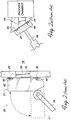
- FIG. 2 illustrates one possible mechanism for opening and closing the slit valve door 21.
- Other mechanisms do, however, exist. Two examples are described in U.S. Patent No. 5,275,303, the disclosures of which are incorporated herein by reference.
- the closure mechanisms 20 shown in FIGs. 2 and 2A includes a slit valve door 21, which comprises an aperture cover plate 22 and a seal 30.
- the closure means, as illustrated, in FIG. 2 appears to have only one linkage 28. This is as a result of the particular view depicted and it is usual for the closure means to include at least two identical and parallel linkages respectively positioned at the opposite ends of the slit valve door 21.
- the linkage 28 in Fig. 2A may be a pneumatically actuated rod.
- the slit valve door 21 is shown to close and seal an aperture 19 in the sidewall 24 of the semiconductor reaction chamber 18.
- the linkage 28 in cooperation with unillustrated pivots, moves the door 21 from an open position (shown in broken lines) 21' away from the chamber sidewall 24 to the sealing position 21 shown in solid line.
- a circumferential O-ring 30 is fitted into a groove 40 in the face 26 of the door 21.
- this O-ring is made of a resilient, compressible, and heat-resistant material. Most commercial O-rings are composed of an elastomeric material.
- the O-ring 30 is typically retained in a dovetail groove 40 formed in the wall-facing face 26 of the door 21.
- the O-ring 30 is press-fitted into the groove 40.
- the side surfaces 42 of the groove 40 slope inwardly up toward the face 26 to form a restriction 46 at the face 26. This restriction is narrower than the diameter of the O-ring 30.
- the O-ring seal is intended to prevent the leakage of process gases through the slit 19 out of the process chamber and to prevent atmosphere from entering to thus reduce contamination therefrom.
- the prior art device described above does not seal the slit 19 as well as might be desired. Because the restriction 46 is narrower than the O-ring 30, the O-ring 30 must be forced past the restriction 46. This can damage the sealing surfaces of the O-ring 30, resulting in leakage of gases into or out of the reaction chamber. The O-ring 30 may also twist during insertion or be unevenly tensioned after insertion. In either case, the O-ring 30 does not have a uniform dimension and does not seat properly in the dovetail groove 40. This results in poor performance and short life, as well as a less effective seal.
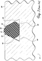
- FIGs. 4 and 4A is a plan view onto the relevant portion of the face 26 of a prior art slit valve door with a dovetail groove 40.
- This groove 40 is typically machined into the door by a router with a dovetail bit.
- the dovetail groove 40 is narrower at its opening 41 than at its bottom surface 44, as indicated in FIG. 3. This makes the groove 40 difficult to machine in such a way that it is uniform along its entire length and such that it does not begin or terminate at an edge of the face 26.
- a uniformly dovetailed groove could be achieved by starting the groove 40 at an edge of the face 26, this is generally considered less ideal than starting the groove 40 by simply plunging the router bit into the face 26.
- the router bit then travels in a closed loop, cutting the dovetail groove 40, and terminates at its starting point.
- This procedure results in a hole 48 at the starting point that is wider than the opening 41 of the groove and whose width is that of the bottom surface 44 of the groove (shown in FIG. 3).
- the restriction 46 of FIG. 3 does not exist and thus there is no retention of the O-ring 30 at that point. This adversely affects the sealing ability of the O-ring 30.
- a small groove 50 is cut in the face 26 such that it is orthogonal to the groove 40 and such that it has a lower surface even with the groove's bottom surface 44. This allows the O-ring 30 to be pried out by means of a small tool inserted in the small groove 50 below the O-ring 30. This creates two problems. First, the O-ring 30 is no longer supported by the sides 42 of the dovetail groove 40. Second, use of the small tool to remove the O-ring 30 may result in damage to the bottom 40 of the dovetail groove near the intersection with the small groove 50. Both of these difficulties reduce the effectiveness of the O-ring seal 30.
- an improved slit valve door for sealing an aperture in the wall of a semiconductor process chamber.
- the door includes an aperture cover plate, a removable insert which fits into a recess in the aperture cover plate, and an O-ring seal which is retained between the aperture cover plate and the insert.
- the aperture cover plate has a recess for receiving the insert, along with an O-ring receiving seat defined by a shoulder and an inwardly angled wall.
- the insert has an angled face which, when the insert is received in the recess, combines with the shoulder and angled wall to define a dovetail groove that retains the O-ring seal between the cover plate and the insert.
- the insert is secured to the cover plate by means of screws which pass from the rear face of the cover plate into the recess and screw into the insert.
- An O-ring is placed over and held by the lower portion of the insert and the lower portion is then inserted into the recess.
- the O-ring moves with the insert into the recess until it contacts the shoulder of the O-ring receiving seat, which prevents the O-ring from moving further into the recess.
- Further tightening of the screws causes the angled face of the insert to come into contact with the O-ring, and the angled face forces the O-ring into contact with the inwardly angled wall of the O-ring receiving seat.
- the O-ring is thus held in place by the shoulder, inwardly angled wall, and angled face. Part of it protrudes beyond the generally uniform face defined by the cover plate and insert, and when the slit valve door is closed, the protruding part of the O-ring comes in contact with the wall of the chamber.
- the O-ring receiving seat has a radiused corner between the shoulder and inwardly angled wall.
- This radiused corner has the advantage of being easier to machine than a sharp corner having an acute angle. It reduces the volume of the pocket between the O-ring, shoulder, and inwardly angled wall, thus reducing the amount of air trapped in the pocket when the O-ring is received in the O-ring seat and reducing the vacuum which tends to hold the O-ring in place and makes removal more difficult.
- One advantage of this invention is that the contamination of the chamber's interior is reduced by providing a more effective seal. This is achieved by reducing the twisting, uneven tensioning, and uneven placement of the O-ring as it is placed in the slit valve door.
- the present invention facilitates removal of the O-ring seal and does not require use of a prying tool which could damage the surfaces of the slit valve door's retaining groove and thus reduce the effectiveness of the seal.
- a further advantage of the present invention is that less stress is placed on the O-ring seal as it is inserted into the slit valve door, reducing the possibility of damage to the O-ring and thus increasing its life. This means the O-ring will not have to be replaced as frequently, which reduces the downtime for replacement of the O-ring.
- Yet another advantage of the present invention is that it can be retrofitted to an existing processing apparatus to replace the prior art slit valve doors as illustrated in FIG. 2.
- a slit valve door retaining the O-ring 30 in accordance with the present invention is shown, and generally indicated as 51. As illustrated, it comprises a first part in the form of an aperture cover plate 52, often referred to as a door, in combination with a second part in the form of an insert 54.
- the cover plate 52 has a recess 56 formed in its face 58 for receiving the insert 54.
- the insert 54 has a seating surface 60 that adjoins the bottom surface 90 of the recess 56 when the cover plate 52 and insert 54 are combined.
- the cover plate 52 further includes an O-ring seat 62, including an inwardly angled wall 66 and a stepped formation which forms a shoulder 64 for supporting the O-ring 30.
- the included angle between the wall 66 and the shoulder 64 is typically 60-63 degrees.
- the wall 66 and the shoulder 64 define two of the three primary sides of a dovetail O-ring retainer.
- the insert 54 has an upper, protruding lip 68, including an angled surface 70, which is formed so that it overhangs the shoulder 64 when the insert 54 is received in the recess 56 and is inwardly angled with respect to the resultant dovetail groove. In this way, the third primary side of the dovetail O-ring retainer is defined.
- the O-ring 30 To insert the O-ring 30, it is first placed over a lower portion 63 of the insert 54 before the insert 54 is lowered into the cover plate 52.
- the lower portion is sized such that the elastic O-ring 30 is held thereon under tension.
- the lower portion 63 of the insert 54 is then inserted into the recess 56 formed in the cover plate 52.
- the O-ring 30 first passes the tip of the cover plate wall 66 and then bears against the shoulder 64 and is prevented from moving further into the recess 56.
- the insert 54 continues to be forced into the recess 56, causing the O-ring 30 to move up against, and thereafter, stretch over, the angled face 70.
- the cover plate 52 has two symetrically placed holes 76 extending from its rear face 80 into the recess 56.
- the insert 54 is joined to the cover plate 52 by means of screws 74, which pass through the holes 76 in the cover plate 52 and screw into holes 78 tapped into the seating surface 60 of the insert 54.
- screws 74 By tightening the screws 74 appropriately, the top wall of insert 54 is pulled into close proximity with the face 58 of the cover plate 52.
- the O-ring 30 which has been placed over the insert 54, is forced into contact with the shoulder 64.
- the shoulder 64 prevents further movement of the O-ring 30 into the recess 56 and forces the O-ring 30 up against the angled face 70. This pushes the O-ring 30 into contact with the wall 66.
- Further tightening of the screws 74 increases the compressive force on the O-ring 30 exerted by the angled surface 70, the wall 66, and the shoulder 64, and thus improves the sealing between the cover plate 52 and the insert 54.
- An improvement to the invention comprises secondary seals 86 between the cover plate 52 and the insert 54.
- Grooves 88 are formed in the recess 56 such that they completely encircle the holes 76.
- Each secondary O-ring seal 86 is placed in a groove 88 and is dimensioned so that when it is placed in the groove 88, it protrudes above the bottom surface 90 of the recess 56.
- the seating surface 60 comes into contact with the secondary O-ring seals 86, thus sealing the holes 74. This has the advantage of further preventing leakage of air between the cover plate 52 and insert 54.
- a further improvement to the invention comprises a radiused corner 82 between the wall 66 and the shoulder 64, as shown in FIG. 6.
- the radiused corner 82 has the advantage of being easier to machine than a sharp corner having an acute angle.
- This feature also has the advantage of reducing the volume of trapped air in the pocket 84 defined between the O-ring 30, the shoulder 64, and the wall 66. This improves the sealing, because when the screws 74 are tightened to place the O-ring 30 under compression, the angled surface 70 forces the O-ring 30 further into the pocket 84 and reduces the volume of the pocket 84.
- the O-ring 30 is already in contact with the wall 66 and the shoulder 64, effectively sealing the pocket 84.
- the trapped air can escape, through strategically placed vents in the wall and shoulder as is a common practice in vacuum applications.
Landscapes
- Engineering & Computer Science (AREA)
- General Engineering & Computer Science (AREA)
- Mechanical Engineering (AREA)
- Container, Conveyance, Adherence, Positioning, Of Wafer (AREA)
- Gasket Seals (AREA)
- Details Of Valves (AREA)
- Sliding Valves (AREA)
- ing And Chemical Polishing (AREA)
- Drying Of Semiconductors (AREA)
- Chemical Vapour Deposition (AREA)
Priority Applications (1)
| Application Number | Priority Date | Filing Date | Title |
|---|---|---|---|
| EP01120661A EP1179835A2 (fr) | 1995-03-31 | 1996-03-29 | Amélioration d'une porte de soupape à fente et méthode d'assemblage |
Applications Claiming Priority (2)
| Application Number | Priority Date | Filing Date | Title |
|---|---|---|---|
| US414420 | 1989-09-29 | ||
| US08/414,420 US5579718A (en) | 1995-03-31 | 1995-03-31 | Slit valve door |
Related Child Applications (1)
| Application Number | Title | Priority Date | Filing Date |
|---|---|---|---|
| EP01120661A Division EP1179835A2 (fr) | 1995-03-31 | 1996-03-29 | Amélioration d'une porte de soupape à fente et méthode d'assemblage |
Publications (2)
| Publication Number | Publication Date |
|---|---|
| EP0735574A1 true EP0735574A1 (fr) | 1996-10-02 |
| EP0735574B1 EP0735574B1 (fr) | 2002-03-13 |
Family
ID=23641384
Family Applications (2)
| Application Number | Title | Priority Date | Filing Date |
|---|---|---|---|
| EP96105015A Expired - Lifetime EP0735574B1 (fr) | 1995-03-31 | 1996-03-29 | Porte de valve à fente améliorée |
| EP01120661A Withdrawn EP1179835A2 (fr) | 1995-03-31 | 1996-03-29 | Amélioration d'une porte de soupape à fente et méthode d'assemblage |
Family Applications After (1)
| Application Number | Title | Priority Date | Filing Date |
|---|---|---|---|
| EP01120661A Withdrawn EP1179835A2 (fr) | 1995-03-31 | 1996-03-29 | Amélioration d'une porte de soupape à fente et méthode d'assemblage |
Country Status (5)
| Country | Link |
|---|---|
| US (1) | US5579718A (fr) |
| EP (2) | EP0735574B1 (fr) |
| JP (1) | JPH1050791A (fr) |
| KR (1) | KR100371996B1 (fr) |
| DE (1) | DE69619717T2 (fr) |
Cited By (8)
| Publication number | Priority date | Publication date | Assignee | Title |
|---|---|---|---|---|
| WO1998045874A1 (fr) * | 1997-04-08 | 1998-10-15 | Tokyo Electron Arizona, Inc. | Appareil de traitement sous vide a joint hermetique generant un faible nombre de particules |
| WO1999003132A1 (fr) * | 1997-07-11 | 1999-01-21 | Applied Materials, Inc. | Porte de soupape a fente en deux pieces comportant un joint coule sur place, utile pour un systeme de traitement a vide |
| WO2000002228A1 (fr) * | 1998-07-03 | 2000-01-13 | Applied Materials, Inc. | Portes a double valve a fente pour traitement au plasma |
| CN103375588A (zh) * | 2012-04-27 | 2013-10-30 | 泰拉半导体株式会社 | 密封件及使用该密封件的基板处理装置 |
| WO2017132205A1 (fr) * | 2016-01-27 | 2017-08-03 | Applied Materials, Inc. | Revêtement d'obturateur de vanne fendue et procédés de nettoyage d'obturateurs de vanne fendue |
| US10023954B2 (en) | 2011-09-15 | 2018-07-17 | Applied Materials, Inc. | Slit valve apparatus, systems, and methods |
| CN109296768A (zh) * | 2017-07-25 | 2019-02-01 | Smc株式会社 | 闸阀门的安装构造 |
| US12692947B2 (en) | 2023-08-17 | 2026-07-28 | Applied Materials, Inc. | Multi-piece slit valve gate |
Families Citing this family (60)
| Publication number | Priority date | Publication date | Assignee | Title |
|---|---|---|---|---|
| US5656082A (en) * | 1994-04-04 | 1997-08-12 | Tatsumo Kabushiki Kaisha | Liquid applying apparatus utilizing centrifugal force |
| KR960002534A (ko) * | 1994-06-07 | 1996-01-26 | 이노우에 아키라 | 감압·상압 처리장치 |
| US5746434A (en) * | 1996-07-09 | 1998-05-05 | Lam Research Corporation | Chamber interfacing O-rings and method for implementing same |
| US6056267A (en) * | 1998-05-19 | 2000-05-02 | Applied Materials, Inc. | Isolation valve with extended seal life |
| US6126527A (en) * | 1998-07-10 | 2000-10-03 | Aplex Inc. | Seal for polishing belt center support having a single movable sealed cavity |
| US6328858B1 (en) | 1998-10-01 | 2001-12-11 | Nexx Systems Packaging, Llc | Multi-layer sputter deposition apparatus |
| US6217272B1 (en) | 1998-10-01 | 2001-04-17 | Applied Science And Technology, Inc. | In-line sputter deposition system |
| US6328316B1 (en) | 1999-01-12 | 2001-12-11 | Dupont Dow Elastomers, L.L.C. | Rubber seal for semi-dynamic applications |
| US6291814B1 (en) * | 1999-06-04 | 2001-09-18 | Utek Semiconductor Corporation | Slit valve with safety detect device |
| US6463203B1 (en) * | 1999-07-29 | 2002-10-08 | Avaya Technology Corp. | High pressure sealed telecommunications equipment enclosure |
| US6682288B2 (en) | 2000-07-27 | 2004-01-27 | Nexx Systems Packaging, Llc | Substrate processing pallet and related substrate processing method and machine |
| US6530733B2 (en) | 2000-07-27 | 2003-03-11 | Nexx Systems Packaging, Llc | Substrate processing pallet and related substrate processing method and machine |
| US6821912B2 (en) | 2000-07-27 | 2004-11-23 | Nexx Systems Packaging, Llc | Substrate processing pallet and related substrate processing method and machine |
| JP4149931B2 (ja) * | 2002-01-31 | 2008-09-17 | デュポン パフォーマンス エラストマーズ エルエルシー | ゲートバルブシールアセンブリ |
| US6824343B2 (en) * | 2002-02-22 | 2004-11-30 | Applied Materials, Inc. | Substrate support |
| US6883776B2 (en) | 2002-08-20 | 2005-04-26 | Asm America, Inc. | Slit valve for a semiconductor processing system |
| TW200407513A (en) * | 2002-11-07 | 2004-05-16 | Wei-Yueh Wu | Gate valve assembly |
| US7100954B2 (en) | 2003-07-11 | 2006-09-05 | Nexx Systems, Inc. | Ultra-thin wafer handling system |
| US7282097B2 (en) * | 2004-06-14 | 2007-10-16 | Applied Materials, Inc. | Slit valve door seal |
| US7422653B2 (en) * | 2004-07-13 | 2008-09-09 | Applied Materials, Inc. | Single-sided inflatable vertical slit valve |
| CN1323250C (zh) * | 2005-06-15 | 2007-06-27 | 黄作兴 | 双向四氟密封蝶阀 |
| TWI295816B (en) | 2005-07-19 | 2008-04-11 | Applied Materials Inc | Hybrid pvd-cvd system |
| US7396001B2 (en) * | 2005-12-20 | 2008-07-08 | Vat Holding Ag | Valve for essentially gastight closing a flow path |
| JP4821314B2 (ja) * | 2005-12-26 | 2011-11-24 | ダイキン工業株式会社 | 半導体製造装置用バルブの弁体およびその製造方法 |
| WO2008046048A2 (fr) * | 2006-10-12 | 2008-04-17 | Parker-Hannifin Corporation | Ensemble de trappe de soupape à fente |
| US20080191474A1 (en) * | 2007-02-12 | 2008-08-14 | Kotz George J | Tri-Lobed O-Ring Seal |
| US7806383B2 (en) * | 2007-06-01 | 2010-10-05 | Applied Materials, Inc. | Slit valve |
| US9383036B2 (en) * | 2007-08-14 | 2016-07-05 | Parker-Hannifin Corporation | Bonded slit valve door seal with thin non-metallic film gap control bumper |
| WO2009055507A1 (fr) * | 2007-10-26 | 2009-04-30 | Applied Materials, Inc. | Procedes et appareil de fermeture hermetique d'un obturateur de clapet à fente |
| US20090184279A1 (en) * | 2008-01-23 | 2009-07-23 | Buckhorn Rubber Products, Inc. | Wedge and covered insert assembly |
| US8011381B2 (en) * | 2008-10-02 | 2011-09-06 | Applied Material, Inc. | Balanced purge slit valve |
| US20100127201A1 (en) * | 2008-11-21 | 2010-05-27 | Applied Materials, Inc. | Interlocking valve chamber and lid |
| DE102009004493B3 (de) * | 2009-01-09 | 2010-06-10 | Sovello Ag | Vakuumbeschichtungsanlage und Verfahren zum Betrieb einer Vakuumbeschichtungsanlage |
| US9010718B2 (en) * | 2009-08-10 | 2015-04-21 | Dean Foote | Seal assembly for a pressure plate in a blowout preventer |
| DE102010053411B4 (de) * | 2009-12-15 | 2023-07-06 | Vat Holding Ag | Vakuumventil |
| CA2782366A1 (fr) | 2009-12-16 | 2011-07-14 | Opko Curna, Llc | Traitement des maladies associees a la peptidase du facteur de transcription liee a la membrane, site 1 (mbtps1) par inhibition du transcrit antisens naturel de la mbtps1 |
| JP4814384B2 (ja) * | 2010-04-05 | 2011-11-16 | 株式会社日立ハイテクノロジーズ | 弁体 |
| JP2013161887A (ja) * | 2012-02-02 | 2013-08-19 | Toyota Motor Corp | 筐体 |
| US20130269599A1 (en) * | 2012-04-13 | 2013-10-17 | Taiwan Semiconductor Manufacturing Company, Ltd. | Methods and Apparatus for Continuous Pressure Control Processing |
| ITMI20120694A1 (it) * | 2012-04-26 | 2013-10-27 | Mib Italiana Spa | Valvola di controllo a petali con guarnizione di tenuta per unita' di collegamento separabili per tubi flessibili. |
| EP2853351B1 (fr) * | 2013-09-27 | 2019-12-25 | Aktiebolaget SKF | Agencement rotatif, procédé de démontage d'un joint et outil de démontage |
| JP6160926B2 (ja) * | 2014-06-05 | 2017-07-12 | Smc株式会社 | ゲートバルブ |
| KR101725250B1 (ko) * | 2015-05-04 | 2017-04-11 | 프리시스 주식회사 | 진공밸브용 블레이드 |
| US10072776B2 (en) | 2015-08-20 | 2018-09-11 | Deere & Company | Fluid connector with annular groove and seal |
| CN112424513B (zh) | 2018-07-19 | 2023-05-23 | 应用材料公司 | 多节点多用途o形环及制作密封的方法 |
| CN111207214A (zh) * | 2018-11-21 | 2020-05-29 | 长鑫存储技术有限公司 | 一种半导体制造设备及用于该设备腔室的阀门 |
| JP7281968B2 (ja) * | 2019-05-30 | 2023-05-26 | 東京エレクトロン株式会社 | アリ溝加工方法及び基板処理装置 |
| US11860059B2 (en) * | 2019-05-31 | 2024-01-02 | Greene, Tweed Technologies, Inc. | Smart seals for monitoring and analysis of seal properties useful in semiconductor valves |
| KR102277809B1 (ko) * | 2019-07-15 | 2021-07-14 | 세메스 주식회사 | 기판 지지 유닛 및 이를 구비하는 기판 처리 시스템 |
| KR102814256B1 (ko) * | 2020-05-29 | 2025-05-30 | 주성엔지니어링(주) | 기판 처리 장치 |
| JP7804393B2 (ja) * | 2020-12-17 | 2026-01-22 | カヤバ株式会社 | 緩衝器 |
| KR102617386B1 (ko) * | 2021-10-07 | 2023-12-27 | (주)다산이엔지 | 진공 게이트 밸브 |
| CN113932011A (zh) * | 2021-11-23 | 2022-01-14 | 深圳市尊绅投资有限公司 | 一种应用于tft、pecvd工艺的腔体真空传输阀门密封组件 |
| KR102909619B1 (ko) * | 2022-06-21 | 2026-01-09 | 주식회사 원익아이피에스 | 도어조립체 및 이를 구비하는 기판처리장치 |
| US12535149B2 (en) * | 2022-06-30 | 2026-01-27 | Srt Co., Ltd | Sealing blade for a slit valve |
| US11867307B1 (en) * | 2022-07-28 | 2024-01-09 | Applied Materials, Inc. | Multi-piece slit valve gate |
| JP2024109212A (ja) * | 2023-02-01 | 2024-08-14 | 株式会社フジキン | 制御弁 |
| KR102802067B1 (ko) * | 2023-02-14 | 2025-05-02 | (주)다산이엔지 | 진공 게이트 밸브 |
| CN117072550B (zh) * | 2023-09-04 | 2026-01-27 | 柳州柳工挖掘机有限公司 | 回转支承和回转作业设备 |
| KR102832185B1 (ko) * | 2024-05-10 | 2025-07-09 | 주식회사 형제정밀 | 기판 제조 설비용 슬릿 밸브 |
Citations (2)
| Publication number | Priority date | Publication date | Assignee | Title |
|---|---|---|---|---|
| EP0453867A1 (fr) * | 1990-04-20 | 1991-10-30 | Applied Materials, Inc. | Appareil et procédé de vanne à fente |
| US5302120A (en) * | 1992-06-15 | 1994-04-12 | Semitool, Inc. | Door assembly for semiconductor processor |
Family Cites Families (21)
| Publication number | Priority date | Publication date | Assignee | Title |
|---|---|---|---|---|
| US2870987A (en) * | 1955-07-08 | 1959-01-27 | Dolphice H Greenwood | Gate valve and sealing means therefor |
| US3000610A (en) * | 1958-10-13 | 1961-09-19 | Grove Valve & Regulator Co | Valve construction |
| JPS5462445A (en) * | 1977-10-28 | 1979-05-19 | Hitachi Ltd | Fitting seal equipment |
| US4376526A (en) * | 1980-08-04 | 1983-03-15 | Seaboard Wellhead Control, Inc. | Seal assembly and valve |
| JPS6158252A (ja) * | 1984-08-29 | 1986-03-25 | Hitachi Ltd | 真空排気リ−ク装置 |
| US4753417A (en) * | 1985-01-28 | 1988-06-28 | The Boc Group, Inc. | Gate valve for vacuum processing apparatus |
| DE3602051A1 (de) * | 1986-01-24 | 1987-07-30 | Schaeffler Waelzlager Kg | Waelzlager-drehverbindung |
| US4721282A (en) * | 1986-12-16 | 1988-01-26 | Lam Research Corporation | Vacuum chamber gate valve |
| US4785962A (en) * | 1987-04-20 | 1988-11-22 | Applied Materials, Inc. | Vacuum chamber slit valve |
| US5188402A (en) * | 1989-01-31 | 1993-02-23 | University Of Florida | Gasket apparatus and hermetically sealed joints employing said gasket apparatus |
| US5002255A (en) * | 1989-03-03 | 1991-03-26 | Irie Koken Kabushiki Kaisha | Non-sliding gate valve for high vacuum use |
| US5120019A (en) * | 1989-08-03 | 1992-06-09 | Brooks Automation, Inc. | Valve |
| US5013009A (en) * | 1989-08-04 | 1991-05-07 | Goddard Valve Corporation | Top entry valve |
| US5226632A (en) * | 1990-04-20 | 1993-07-13 | Applied Materials, Inc. | Slit valve apparatus and method |
| JPH0478377A (ja) * | 1990-07-20 | 1992-03-12 | Tokyo Electron Ltd | トグル式ゲート |
| US5275303A (en) * | 1992-02-03 | 1994-01-04 | Applied Materials, Inc. | Valve closure mechanism for semiconductor deposition apparatus |
| US5236345A (en) * | 1992-02-11 | 1993-08-17 | Nevrekar Venkatesh R | Expanding gate valve assembly |
| US5271602A (en) * | 1992-04-13 | 1993-12-21 | The Japan Steel Works Ltd. | Vacuum gate valve |
| US5341835A (en) * | 1992-12-14 | 1994-08-30 | Foster Valve Corporation | Lubrication system for valve seat of a gate valve |
| US5363872A (en) * | 1993-03-16 | 1994-11-15 | Applied Materials, Inc. | Low particulate slit valve system and method for controlling same |
| US5379984A (en) * | 1994-01-11 | 1995-01-10 | Intevac, Inc. | Gate valve for vacuum processing system |
-
1995
- 1995-03-31 US US08/414,420 patent/US5579718A/en not_active Expired - Fee Related
-
1996
- 1996-03-29 EP EP96105015A patent/EP0735574B1/fr not_active Expired - Lifetime
- 1996-03-29 DE DE69619717T patent/DE69619717T2/de not_active Expired - Fee Related
- 1996-03-29 EP EP01120661A patent/EP1179835A2/fr not_active Withdrawn
- 1996-03-30 KR KR1019960009968A patent/KR100371996B1/ko not_active Expired - Fee Related
- 1996-04-01 JP JP8079084A patent/JPH1050791A/ja active Pending
Patent Citations (2)
| Publication number | Priority date | Publication date | Assignee | Title |
|---|---|---|---|---|
| EP0453867A1 (fr) * | 1990-04-20 | 1991-10-30 | Applied Materials, Inc. | Appareil et procédé de vanne à fente |
| US5302120A (en) * | 1992-06-15 | 1994-04-12 | Semitool, Inc. | Door assembly for semiconductor processor |
Cited By (10)
| Publication number | Priority date | Publication date | Assignee | Title |
|---|---|---|---|---|
| WO1998045874A1 (fr) * | 1997-04-08 | 1998-10-15 | Tokyo Electron Arizona, Inc. | Appareil de traitement sous vide a joint hermetique generant un faible nombre de particules |
| US6032419A (en) * | 1997-04-08 | 2000-03-07 | Tokyo Electron Limited | Vacuum processing apparatus with low particle generating vacuum seal |
| WO1999003132A1 (fr) * | 1997-07-11 | 1999-01-21 | Applied Materials, Inc. | Porte de soupape a fente en deux pieces comportant un joint coule sur place, utile pour un systeme de traitement a vide |
| US6089543A (en) * | 1997-07-11 | 2000-07-18 | Applied Materials, Inc. | Two-piece slit valve door with molded-in-place seal for a vacuum processing system |
| WO2000002228A1 (fr) * | 1998-07-03 | 2000-01-13 | Applied Materials, Inc. | Portes a double valve a fente pour traitement au plasma |
| US10023954B2 (en) | 2011-09-15 | 2018-07-17 | Applied Materials, Inc. | Slit valve apparatus, systems, and methods |
| CN103375588A (zh) * | 2012-04-27 | 2013-10-30 | 泰拉半导体株式会社 | 密封件及使用该密封件的基板处理装置 |
| WO2017132205A1 (fr) * | 2016-01-27 | 2017-08-03 | Applied Materials, Inc. | Revêtement d'obturateur de vanne fendue et procédés de nettoyage d'obturateurs de vanne fendue |
| CN109296768A (zh) * | 2017-07-25 | 2019-02-01 | Smc株式会社 | 闸阀门的安装构造 |
| US12692947B2 (en) | 2023-08-17 | 2026-07-28 | Applied Materials, Inc. | Multi-piece slit valve gate |
Also Published As
| Publication number | Publication date |
|---|---|
| EP0735574B1 (fr) | 2002-03-13 |
| EP1179835A2 (fr) | 2002-02-13 |
| KR100371996B1 (ko) | 2003-04-10 |
| DE69619717T2 (de) | 2002-11-07 |
| JPH1050791A (ja) | 1998-02-20 |
| KR960035774A (ko) | 1996-10-28 |
| DE69619717D1 (de) | 2002-04-18 |
| US5579718A (en) | 1996-12-03 |
Similar Documents
| Publication | Publication Date | Title |
|---|---|---|
| US5579718A (en) | Slit valve door | |
| JP2001509647A (ja) | 真空処理システムにおける2ピース式スリットバルブインサート | |
| US5724748A (en) | Apparatus for packaging contaminant-sensitive articles and resulting package | |
| US6089543A (en) | Two-piece slit valve door with molded-in-place seal for a vacuum processing system | |
| US7754014B2 (en) | Gas-purged vacuum valve | |
| US5421401A (en) | Compound clamp ring for semiconductor wafers | |
| US6397446B1 (en) | Face seal O-ring insertion tool | |
| US2782574A (en) | Work holder | |
| US5150734A (en) | Processing apparatus at reduced pressure and valve used therefor | |
| US20020005369A1 (en) | Door guide for a wafer container | |
| JP2001187972A (ja) | ゲートバルブ | |
| EP1028278A2 (fr) | Joint d'étanchéité d'une soupape | |
| EP1062468B1 (fr) | Dispositif de conditionnement d'articles sensibles aux contaminants | |
| JP2024524063A (ja) | 扉ガスケットを有する基板容器 | |
| KR20000003211A (ko) | 로드 락 챔버의 가스 공급 시스템 | |
| JP2000349064A (ja) | 半導体ウェハーの片面エッチング装置 | |
| JPH11101356A (ja) | Oリングを有する密閉構造 | |
| JPH08288361A (ja) | 真空処理装置 | |
| KR20000018774A (ko) | 화학 기상 증착장치용 반응로의 오링이 구비된 플랜지 및 그 오링 제거기구 | |
| JPH06314678A (ja) | 密閉式洗浄装置 | |
| JPH09257135A (ja) | 真空処理装置の弁体シール装置 | |
| KR100577564B1 (ko) | 반도체 제조용 챔버 도어의 오링 조립 장치 | |
| US6491178B1 (en) | Upper cover plate for an air-tight chamber and a tool for removing the same | |
| HK40116528A (en) | Sluice valve installation method and sluice valve installation structure used in said sluice valve installation method | |
| KR20030061638A (ko) | 반도체장치 제조설비용 카세트 |
Legal Events
| Date | Code | Title | Description |
|---|---|---|---|
| PUAI | Public reference made under article 153(3) epc to a published international application that has entered the european phase |
Free format text: ORIGINAL CODE: 0009012 |
|
| AK | Designated contracting states |
Kind code of ref document: A1 Designated state(s): DE GB |
|
| 17P | Request for examination filed |
Effective date: 19970327 |
|
| 17Q | First examination report despatched |
Effective date: 19990219 |
|
| GRAG | Despatch of communication of intention to grant |
Free format text: ORIGINAL CODE: EPIDOS AGRA |
|
| GRAG | Despatch of communication of intention to grant |
Free format text: ORIGINAL CODE: EPIDOS AGRA |
|
| GRAG | Despatch of communication of intention to grant |
Free format text: ORIGINAL CODE: EPIDOS AGRA |
|
| GRAH | Despatch of communication of intention to grant a patent |
Free format text: ORIGINAL CODE: EPIDOS IGRA |
|
| GRAH | Despatch of communication of intention to grant a patent |
Free format text: ORIGINAL CODE: EPIDOS IGRA |
|
| REG | Reference to a national code |
Ref country code: GB Ref legal event code: IF02 |
|
| GRAA | (expected) grant |
Free format text: ORIGINAL CODE: 0009210 |
|
| AK | Designated contracting states |
Kind code of ref document: B1 Designated state(s): DE GB |
|
| REF | Corresponds to: |
Ref document number: 69619717 Country of ref document: DE Date of ref document: 20020418 |
|
| PLBE | No opposition filed within time limit |
Free format text: ORIGINAL CODE: 0009261 |
|
| STAA | Information on the status of an ep patent application or granted ep patent |
Free format text: STATUS: NO OPPOSITION FILED WITHIN TIME LIMIT |
|
| 26N | No opposition filed |
Effective date: 20021216 |
|
| PGFP | Annual fee paid to national office [announced via postgrant information from national office to epo] |
Ref country code: GB Payment date: 20030324 Year of fee payment: 8 |
|
| PGFP | Annual fee paid to national office [announced via postgrant information from national office to epo] |
Ref country code: DE Payment date: 20030328 Year of fee payment: 8 |
|
| PG25 | Lapsed in a contracting state [announced via postgrant information from national office to epo] |
Ref country code: GB Free format text: LAPSE BECAUSE OF NON-PAYMENT OF DUE FEES Effective date: 20040329 |
|
| PG25 | Lapsed in a contracting state [announced via postgrant information from national office to epo] |
Ref country code: DE Free format text: LAPSE BECAUSE OF NON-PAYMENT OF DUE FEES Effective date: 20041001 |
|
| GBPC | Gb: european patent ceased through non-payment of renewal fee |
Effective date: 20040329 |