EP0735620A2 - Commande d'assistance à la mise en place ou à la séparation d'un connecteur électrique dans/ou de sa position de connexion - Google Patents
Commande d'assistance à la mise en place ou à la séparation d'un connecteur électrique dans/ou de sa position de connexion Download PDFInfo
- Publication number
- EP0735620A2 EP0735620A2 EP96103553A EP96103553A EP0735620A2 EP 0735620 A2 EP0735620 A2 EP 0735620A2 EP 96103553 A EP96103553 A EP 96103553A EP 96103553 A EP96103553 A EP 96103553A EP 0735620 A2 EP0735620 A2 EP 0735620A2
- Authority
- EP
- European Patent Office
- Prior art keywords
- electrical connector
- circuit board
- aid according
- actuating aid
- actuating
- Prior art date
- Legal status (The legal status is an assumption and is not a legal conclusion. Google has not performed a legal analysis and makes no representation as to the accuracy of the status listed.)
- Ceased
Links
Images


Classifications
-
- H—ELECTRICITY
- H01—ELECTRIC ELEMENTS
- H01R—ELECTRICALLY-CONDUCTIVE CONNECTIONS; STRUCTURAL ASSOCIATIONS OF A PLURALITY OF MUTUALLY-INSULATED ELECTRICAL CONNECTING ELEMENTS; COUPLING DEVICES; CURRENT COLLECTORS
- H01R13/00—Details of coupling devices of the kinds covered by groups H01R12/70 or H01R24/00 - H01R33/00
- H01R13/62—Means for facilitating engagement or disengagement of coupling parts or for holding them in engagement
- H01R13/629—Additional means for facilitating engagement or disengagement of coupling parts, e.g. aligning or guiding means, levers, gas pressure electrical locking indicators, manufacturing tolerances
- H01R13/62933—Comprising exclusively pivoting lever
-
- H—ELECTRICITY
- H05—ELECTRIC TECHNIQUES NOT OTHERWISE PROVIDED FOR
- H05K—PRINTED CIRCUITS; CASINGS OR CONSTRUCTIONAL DETAILS OF ELECTRIC APPARATUS; MANUFACTURE OF ASSEMBLAGES OF ELECTRICAL COMPONENTS
- H05K7/00—Constructional details common to different types of electric apparatus
- H05K7/14—Mounting supporting structure in casing or on frame or rack
- H05K7/1401—Mounting supporting structure in casing or on frame or rack comprising clamping or extracting means
- H05K7/1402—Mounting supporting structure in casing or on frame or rack comprising clamping or extracting means for securing or extracting printed circuit boards
-
- H—ELECTRICITY
- H01—ELECTRIC ELEMENTS
- H01R—ELECTRICALLY-CONDUCTIVE CONNECTIONS; STRUCTURAL ASSOCIATIONS OF A PLURALITY OF MUTUALLY-INSULATED ELECTRICAL CONNECTING ELEMENTS; COUPLING DEVICES; CURRENT COLLECTORS
- H01R12/00—Structural associations of a plurality of mutually-insulated electrical connecting elements, specially adapted for printed circuits, e.g. printed circuit boards [PCB], flat or ribbon cables, or like generally planar structures, e.g. terminal strips, terminal blocks; Coupling devices specially adapted for printed circuits, flat or ribbon cables, or like generally planar structures; Terminals specially adapted for contact with, or insertion into, printed circuits, flat or ribbon cables, or like generally planar structures
- H01R12/70—Coupling devices
- H01R12/7005—Guiding, mounting, polarizing or locking means; Extractors
Definitions
- the present invention relates to an actuating aid for bringing and / or releasing an electrical connector into or out of its connecting position, in which it electrically connects a first printed circuit board to a second printed circuit board.
- actuation aids for producing and releasing an electrical plug connection cannot generally be used, in particular in the case of printed circuit board connectors, because these are normally very difficult to access.
- the known actuation aids can help to reduce the effort required by the user, but the forces acting on the printed circuit boards and the associated dangers and disadvantages remain unchanged.
- the present invention is therefore based on the object of developing an actuating aid according to the preamble of claim 1 in such a way that it can also be used in printed circuit board connectors and in a way by which the load on the printed circuit boards when making and releasing the connection is simple and reliable to a minimum is reducible.
- an end section of the actuating aid facing the electrical connector is designed in such a way that a holding mechanism can be actuated with it, which is capable of holding the electrical connector in the connecting position and that an end section of the actuating aid facing away from the electrical connector extends into a region outside the first and / or second printed circuit board and is designed such that actuation of this end section actuates of the holding mechanism is triggered by the end section of the actuating aid facing the electrical connector.
- the actuation aid is designed in such a way that the process of inserting or withdrawing a circuit board onto or from another circuit board is not simply supported, but rather that only the holding mechanism holding the electrical connector in the connection position can be actuated by the actuation aid, and that without locally separating the connected or to be connected circuit boards from each other. That is, it is possible - in contrast to the known actuation aids - to establish and release the mechanical and electrical connection between the electrical connector and a circuit board to be contacted or contacted on the one hand and the insertion and removal of the circuit board in or out to completely separate the electrical connector from one another.
- the circuit board can be inserted and removed from the electrical connector by using the holding mechanism which can be remotely controlled by means of the actuating aid according to the invention, without effort and thus without risk to the circuit board.
- the actuating aid according to the invention can therefore also be used in printed circuit board connectors and in such a way that a load on the printed circuit boards when making and releasing the connection can be reduced to a minimum in a simple and reliable manner.
- FIG. 1 shows a schematic view of two printed circuit boards, which according to the invention can be connected via an electrical connector using a suitable actuation aid.
- the electrical connector is designated by reference number 1.
- the circuit boards to be connected by the electrical connector are a rear wall circuit board 2 and an assembly circuit board 3.
- connection is intended to electrically connect the surface of the rear wall circuit board 2 and one or both surface (s) of the module circuit board 3, more precisely to the contact points provided on the respective surfaces, the module circuit board 3 in the connected state with the interposition of the electrical Connector 1 is plugged onto the surface of the rear wall circuit board 2.
- the electrical connector 1 is held on the rear wall circuit board 2 by guide and holding walls 21 mounted on the rear wall circuit board 2.
- the guide and retaining walls 21 have a multiplicity of connector locking devices in the form of inwardly projecting resilient retaining tabs 22 which snap into recesses (not shown) provided in the housing of the electrical connector 1 and in the connected state for a secure mechanical and electrical connection between the provide electrical connector 1 and the backplane circuit board 2.
- the electrical connector 1 has, at its end facing the assembly circuit board 3 according to FIG. 1, a recess 11 for receiving the assembly circuit board 3.
- the electrical connector has a first half 12 and a second half 13, which can be expanded and collapsed to a certain extent at the end facing the assembly circuit board 3.
- the electrical connector 1 is shown in an assembly position in which the first half 12 and the second half 13 of which are unfolded.
- the recess 11 is relatively large and enables the assembly circuit board 3 to be inserted into the recess 11 essentially without force.
- the first half 12 and the second half 13 of the electrical connector 1 are folded so far that one between the surfaces of the assembly circuit board 3 and the first and the second half of the electrical connector safe and reliable electrical and mechanical connection is guaranteed.
- the assembly circuit board 3 can be pulled out of the electrical connector 1 at most while damaging the assembly circuit board and / or the electrical connector.
- a holding mechanism provided on the electrical connector must be actuated in the form of one or more toggle levers 14.
- two toggle levers 14 are provided.
- the application of a pressing force on the toggle levers 14 forces the electrical connector in its connecting position.
- the toggle levers are stretched and finally pushed through their dead center. After passing the dead center, the toggle levers snap into an end position, which they maintain without any further application of force.
- the electrical connector has assumed its connecting position in which it electrically connects the rear wall circuit board 2 to the assembly circuit board 3.
- the electrical connector By exerting a tensile force on the toggle lever 14, the electrical connector can be brought back into its assembly position.
- the holding mechanism is advantageously designed such that the electrical connector is forced into the mounting position during this process.
- the actuation aid according to the invention is provided in the form of one or more push rods 31.
- the actuation aid according to the invention is provided in the form of one or more push rods 31.
- two push rods 31 running side by side are provided.
- the push rods 31 are guided parallel to the surface of the assembly circuit board through corresponding openings in a guide web 32 mounted on the assembly circuit board 3 and a cover plate 33 likewise assembled on the assembly circuit board 3.
- the push rods can be placed anywhere along the toggle system. This fact and also the fact that the push rod are guided at any distance from the surface of the assembly circuit board can offer maximum freedom when assembling the component circuit board.
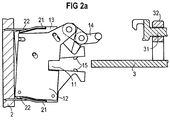
- FIGS. 2A to 2C For a detailed explanation of the function and the interaction of the push rods 31 and the toggle levers 14, reference is now made to FIGS. 2A to 2C.
- FIGS. 2A to 2C illustrate the establishment of the connection between the electrical connector 1 and the assembly circuit board 3.
- Figure 2A shows the electrical connector in its assembled position.
- the first half 12 and the second half 13 are unfolded in order to open the circuit board recess 11 in the electrical connector to such an extent that the assembly circuit board 3 can be inserted into it without the use of force.
- first half 12 and the second half 13 of the electrical connector can also be folded and unfolded due to their special design when the electrical connector 1 is inserted between the guide and retaining walls 21 and held there by the retaining tabs 22 becomes.
- the halves When the first half 12 and the second half 13 of the electrical connector are folded together and unfolded, the halves are pivoted about respective end sections of the retaining tabs 22 in opposite directions. Since the retaining tabs 22, which each act as pivot points, never leave the corresponding cutouts in the connector housing, the halves of the electrical connector cannot fall out of the guide and retaining walls 21 neither in the connected state nor in the assembled state of the electrical connector.
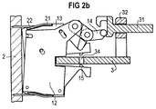
- FIG. 2B The state in which the assembly circuit board is inserted into the cutout of the electrical connector is shown in FIG. 2B.
- the electrical connector is still in the assembly position.
- the insertion of the assembly circuit board 3 into the corresponding recess 11 in the electrical connector does not change this.
- the push rods 31 are pressed by the operator toward the electrical connector. By actuating the push rods 31, they come into contact with the respective toggle levers 14 assigned to them and exert pressure on them.
- a holding mechanism which can be actuated as described above makes it possible to dispense with the provision of free spaces on the respective printed circuit boards which are usually required for attaching the conventional actuating aids and are not equipped with components.
- connection position of the electrical connector is shown in Figure 2C.
- the first and second halves of the electrical connector have a strong desire to return to the mounting position for reasons described in more detail later, the connection position is maintained in this position due to the locking action of the toggle lever.
- the push rods are force-free in this state.
- both the backplane circuit board 2 and the assembly circuit board 2 are both mechanically and electrically connected to the electrical connector.
- the mechanical connection between the assembly circuit board and the electrical connector comes about in that the assembly circuit board 3 is clamped in the connecting position between the first half and the second half of the electrical connector 1.
- the assembly circuit board is additionally held in this state also by projections 15 provided on the first and second halves, which engage in corresponding recesses 34 on the assembly circuit board 3 in the connected state of the electrical connector.
- the electrical connection between the assembly circuit board and the electrical connector comes about in that, in the clamped area of the upper and / or lower surface of the assembly circuit board, contacting devices, not shown, are provided, which in the connected state of on correspondingly arranged contacting devices on the first and second half of the electrical connector can be contacted.
- These contacting devices can be of any type. These can be conventional knife and female connectors or else completely different devices.
- the two-sided contacting devices prefferably be designed as essentially flat contact surfaces which, in the connected state, are pressed onto one another essentially frontally.
- the pressing together can be done solely by clamping the assembly circuit board 3 between the first and the second half of the electrical connector 1, but it can also be done exclusively or additionally by means of elastic elements such as springs or the like which are provided in the contacting devices and press the mutually associated contact surfaces against one another.
- Providing the contacting devices with springs for example, on the one hand contributes to a more secure and reliable contacting, and on the other hand facilitates and even supports the opening of the first and the second half of the electrical connector during the transition from the connection position into the mounting position.
- the push rod 31 is accordingly latched into a holding position together with the toggle lever 14.
- the push rod position assumed in the connecting position of the electrical connector and the engagement in this position when the toggle lever is pressed through its dead center give the operator options to determine the position currently occupied by the electrical connector.
- the push rod must simply be pulled back from the electrical connector. This pulling out of the push rod from the end panel of the assembly circuit board, as a result of the connection existing in this state between the push rod and the toggle lever, simultaneously actuates the toggle lever. As soon as the toggle lever is pivoted back over its dead center, the first and the second half of the electrical connector and the push rod are through the toggle lever is no longer held, ie it can move freely. This state corresponds approximately to the state shown in FIG. 2B.
- the assembly board can be removed in the assembly position of the electrical connector, since in this state there are neither mechanical nor electrical connections between the electrical connector and the assembly board, also without the use of force.
- An actuating aid for bringing and / or releasing an electrical connector into or out of its connecting position has thus been created, which can also be used in printed circuit board connectors and in a way by which the loading of the printed circuit boards when making and releasing the connection is simple and reliable Minimum is reducible.
- the structure according to the invention can also be used extremely advantageously in systems in which it is important to make the electrical connection of the connections to be connected in a specific sequence, that is, if it is necessary, for example, the electrical connection of the ground connections before the connection of the other connections to make.
- connection system described in the present application could be used for the connections to be contacted later.
- connections which can be contacted via the conventional connectors with the male and female connectors or the like would be electrically and mechanically connected to one another immediately when the assembly circuit board was plugged onto the rear wall circuit board.
- the connections which can be contacted via the connection system according to the invention are neither electrically nor mechanically connected to the electrical connector by the plugging on; rather, the connection takes place only when the holding mechanism is actuated by means of the actuating aid and, if appropriate, can again be made selectively in a specific further sequence.
- connection systems for staggered connection of the connections to be connected, it is also possible to provide a plurality of connection systems of the type described in the present application which can be operated separately.
- connection system described thus combines a large number of positive properties which cannot be achieved with conventional systems at all or only with the acceptance of not inconsiderable disadvantages.
Landscapes
- Engineering & Computer Science (AREA)
- Microelectronics & Electronic Packaging (AREA)
- Coupling Device And Connection With Printed Circuit (AREA)
- Details Of Connecting Devices For Male And Female Coupling (AREA)
- Mounting Of Printed Circuit Boards And The Like (AREA)
Applications Claiming Priority (2)
| Application Number | Priority Date | Filing Date | Title |
|---|---|---|---|
| DE19511509A DE19511509C2 (de) | 1995-03-29 | 1995-03-29 | Elektrischer Leiterplattenverbinder |
| DE19511509 | 1995-03-29 |
Publications (2)
| Publication Number | Publication Date |
|---|---|
| EP0735620A2 true EP0735620A2 (fr) | 1996-10-02 |
| EP0735620A3 EP0735620A3 (fr) | 1998-04-22 |
Family
ID=7758048
Family Applications (1)
| Application Number | Title | Priority Date | Filing Date |
|---|---|---|---|
| EP96103553A Ceased EP0735620A3 (fr) | 1995-03-29 | 1996-03-06 | Commande d'assistance à la mise en place ou à la séparation d'un connecteur électrique dans/ou de sa position de connexion |
Country Status (4)
| Country | Link |
|---|---|
| US (1) | US5906501A (fr) |
| EP (1) | EP0735620A3 (fr) |
| JP (1) | JP3127118B2 (fr) |
| DE (1) | DE19511509C2 (fr) |
Cited By (1)
| Publication number | Priority date | Publication date | Assignee | Title |
|---|---|---|---|---|
| US7847772B2 (en) | 2005-12-07 | 2010-12-07 | Lg Display, Co., Ltd. | Fabricating method and fabricating apparatus thereof, and picture quality controlling method and apparatus thereof |
Families Citing this family (19)
| Publication number | Priority date | Publication date | Assignee | Title |
|---|---|---|---|---|
| EP1016335B1 (fr) * | 1997-09-15 | 2001-12-19 | Siemens Aktiengesellschaft | Appareil electrique a element d'ajustage |
| DE29805024U1 (de) * | 1998-03-19 | 1999-08-05 | Siemens AG, 80333 München | Verriegelungsmechanismus eines steckbaren Kontaktiereinschubes |
| DE19828314C1 (de) * | 1998-06-25 | 2000-02-24 | Bosch Gmbh Robert | Verfahren und Vorrichtung zum Verbinden einer Sonde mit Leiterplatte mit einem aus zwei Halbschalen bestehenden Verbindungsstecker |
| US6056574A (en) * | 1998-09-29 | 2000-05-02 | The Whitaker Corporation | Retention assembly with cap for processor modules |
| DE19912858A1 (de) | 1999-03-22 | 2000-10-19 | Tyco Electronics Logistics Ag | System mit zusammensteckbaren Leiterplatten |
| US6551120B2 (en) * | 1999-09-02 | 2003-04-22 | Intel Corporation | Card retention mechanism |
| AU2001230439A1 (en) | 2000-02-11 | 2001-08-20 | Tyco Electronics Belgium Ec N.V. | Printed circuit board |
| EP1254494B1 (fr) | 2000-02-11 | 2003-10-01 | Tyco Electronics Belgium EC N.V. | Carte de circuit imprime et ensemble de connecteurs |
| US6431890B1 (en) | 2000-08-08 | 2002-08-13 | Kin Ip Li | Printed circuit board socket with guides for aligning and for releasing a printed circuit board |
| US6549422B1 (en) * | 2000-12-28 | 2003-04-15 | Cisco Technology, Inc. | Electronic system fire containment and suppression |
| USD464875S1 (en) | 2001-05-18 | 2002-10-29 | Scott Koppang | Cord organizer |
| US7581959B2 (en) * | 2007-04-30 | 2009-09-01 | Newlsys, Inc. | Printed circuit board engagement systems and methods |
| JP5491328B2 (ja) * | 2010-09-01 | 2014-05-14 | 株式会社東海理化電機製作所 | プラグロック構造 |
| DE102011006936B4 (de) | 2011-04-07 | 2018-03-15 | Robert Bosch Gmbh | Steckersystem mit Schließhebel und Übersetzung |
| JP5781846B2 (ja) * | 2011-07-01 | 2015-09-24 | 矢崎総業株式会社 | コネクタ装置 |
| TWI441578B (zh) * | 2012-01-11 | 2014-06-11 | Delta Electronics Inc | 電路板組合 |
| USD704667S1 (en) | 2012-10-30 | 2014-05-13 | Gary L. Sharpe | Cord organizer |
| USD722980S1 (en) * | 2014-04-25 | 2015-02-24 | Xerox Corporation | Latch apparatus for retaining a flexible circuit cable within a receptacle mounted on a circuit board |
| US9184522B1 (en) | 2014-04-25 | 2015-11-10 | Xerox Corporation | Latch apparatus for retaining a flexible circuit cable within a receptacle mounted on a circuit board |
Family Cites Families (14)
| Publication number | Priority date | Publication date | Assignee | Title |
|---|---|---|---|---|
| US3130351A (en) * | 1961-09-14 | 1964-04-21 | George J Giel | Modular circuitry apparatus |
| US3475717A (en) * | 1967-03-31 | 1969-10-28 | Itt | Zero force connector |
| JPS511637B2 (fr) * | 1973-05-22 | 1976-01-19 | ||
| US3853379A (en) * | 1973-07-20 | 1974-12-10 | Itt | Printed circuit board connector assembly |
| US4159154A (en) * | 1978-04-10 | 1979-06-26 | International Telephone And Telegraph Corporation | Zero insertion force connector |
| US4509812A (en) * | 1982-04-21 | 1985-04-09 | Karl Lotter | Plug connector for dil components |
| US4846730A (en) * | 1987-09-03 | 1989-07-11 | Gte Products Corporation | Daughter board stabilizer for rotary cam ZIF edge card connector |
| JPH01162291U (fr) * | 1988-04-14 | 1989-11-10 | ||
| JPH0359977A (ja) * | 1989-07-28 | 1991-03-14 | Fuji Seiko Honsha:Kk | コネクタ装置 |
| JP2830634B2 (ja) * | 1992-08-05 | 1998-12-02 | 日本電気株式会社 | パッケージ基板 |
| DE4241256C2 (de) * | 1992-12-08 | 2001-08-16 | Framatome Connectors Int | Elektrischer Steckverbinder |
| US5398164A (en) * | 1993-02-24 | 1995-03-14 | International Business Machines Corporation | Printed circuit card latching and stiffening assembly |
| US5506758A (en) * | 1994-09-30 | 1996-04-09 | Hewlett-Packard Company | Circuit board inserter and extractor |
| US5601349A (en) * | 1995-07-25 | 1997-02-11 | Dell U.S.A., Lp | Captive latch mechanism for use with an expansion card cage in a personal computer |
-
1995
- 1995-03-29 DE DE19511509A patent/DE19511509C2/de not_active Expired - Fee Related
-
1996
- 1996-03-06 EP EP96103553A patent/EP0735620A3/fr not_active Ceased
- 1996-03-27 JP JP08095889A patent/JP3127118B2/ja not_active Expired - Fee Related
- 1996-03-29 US US08/625,632 patent/US5906501A/en not_active Expired - Fee Related
Cited By (1)
| Publication number | Priority date | Publication date | Assignee | Title |
|---|---|---|---|---|
| US7847772B2 (en) | 2005-12-07 | 2010-12-07 | Lg Display, Co., Ltd. | Fabricating method and fabricating apparatus thereof, and picture quality controlling method and apparatus thereof |
Also Published As
| Publication number | Publication date |
|---|---|
| DE19511509C2 (de) | 1999-05-12 |
| EP0735620A3 (fr) | 1998-04-22 |
| US5906501A (en) | 1999-05-25 |
| JPH08273756A (ja) | 1996-10-18 |
| DE19511509A1 (de) | 1996-10-02 |
| JP3127118B2 (ja) | 2001-01-22 |
Similar Documents
| Publication | Publication Date | Title |
|---|---|---|
| EP0735620A2 (fr) | Commande d'assistance à la mise en place ou à la séparation d'un connecteur électrique dans/ou de sa position de connexion | |
| DE69609643T2 (de) | Verriegelungsmechanismus für Verbindergehäuse | |
| DE68916373T2 (de) | Bestückungs- und ausziehvorrichtung für gedruckte schaltungen für elektronische anordnungen. | |
| DE69728809T2 (de) | Verbindungsanordnung in einem Stecker | |
| DE69822393T2 (de) | Elektrischer Steckverbinder für flexible Flachband-Schaltkreise | |
| DE2166754C3 (de) | Verschiebewerkzeug zum Herstellen und Trennen einer elektrischen Steckkontaktverbindung | |
| DE102018217838B4 (de) | Elektrischer anschluss mit hilfshebel | |
| DE69027345T2 (de) | Verstärkte Verbinderverriegelung | |
| WO2017046129A1 (fr) | Borne de raccord pour raccorder un conducteur électrique | |
| DE60221944T2 (de) | Verbinder mit Kupplungseinrichtung | |
| DE102008035193A1 (de) | Kontrollierbare Steckverbindung und Verfahren zur Kontrolle des Steckzustandes einer Steckverbindung | |
| DE102016102071B3 (de) | Elektrische Steckverbinderanordnung und Löseelement hierzu | |
| DE68902993T2 (de) | System zum schnellen ein- und abbauen eines gestells an einen haltetraeger. | |
| EP0735623A2 (fr) | Connecteur électrique | |
| DE2912740A1 (de) | Vorrichtung zum entriegeln und herausziehen fuer eine elektrische verbindung sowie mit einer derartigen vorrichtung ausgeruestete elektrische verbindung | |
| WO2005096449A1 (fr) | Partie de connexion electrique par enfichage a force d'insertion nulle | |
| DE102006054647A1 (de) | Elektrische Steckverbinderkupplung | |
| EP4324051B1 (fr) | Dispositif de contact de type ressort de serrage doté d'un mécanisme de prévention de dépassement, et insert de connecteur enfichable comportant au moins un tel dispositif de contact de type ressort de serrage | |
| DE69010397T2 (de) | Elektrische Verbindungsvorrichtung. | |
| WO1997008783A1 (fr) | Dispositif constitue de deux demi-fiches pour fixation dans une paroi | |
| DE102007039064A1 (de) | Elektronisches Gerät und Leiterplatte mit Steckerleiste | |
| DE112022002668T5 (de) | Verriegelungsvorrichtung, Entriegelungsvorrichtung und Verriegelungs- und Entriegelungsanordnung | |
| DE102007034249B4 (de) | Schaltbetätigungsanordnung | |
| DE112016004637T5 (de) | Elektrische Verbindungsvorrichtung | |
| DE3604548C2 (fr) |
Legal Events
| Date | Code | Title | Description |
|---|---|---|---|
| PUAI | Public reference made under article 153(3) epc to a published international application that has entered the european phase |
Free format text: ORIGINAL CODE: 0009012 |
|
| AK | Designated contracting states |
Kind code of ref document: A2 Designated state(s): AT BE CH DE FR GB IT LI NL SE |
|
| PUAL | Search report despatched |
Free format text: ORIGINAL CODE: 0009013 |
|
| AK | Designated contracting states |
Kind code of ref document: A3 Designated state(s): AT BE CH DE FR GB IT LI NL SE |
|
| 17P | Request for examination filed |
Effective date: 19980618 |
|
| 17Q | First examination report despatched |
Effective date: 19991115 |
|
| RAP1 | Party data changed (applicant data changed or rights of an application transferred) |
Owner name: TYCO ELECTRONICS LOGISTICS AG |
|
| GRAG | Despatch of communication of intention to grant |
Free format text: ORIGINAL CODE: EPIDOS AGRA |
|
| STAA | Information on the status of an ep patent application or granted ep patent |
Free format text: STATUS: THE APPLICATION HAS BEEN REFUSED |
|
| 18R | Application refused |
Effective date: 20021209 |