EP0735641A1 - Système de commande de charge pour utilisation dans un moteur à combustion interne - Google Patents
Système de commande de charge pour utilisation dans un moteur à combustion interne Download PDFInfo
- Publication number
- EP0735641A1 EP0735641A1 EP95119637A EP95119637A EP0735641A1 EP 0735641 A1 EP0735641 A1 EP 0735641A1 EP 95119637 A EP95119637 A EP 95119637A EP 95119637 A EP95119637 A EP 95119637A EP 0735641 A1 EP0735641 A1 EP 0735641A1
- Authority
- EP
- European Patent Office
- Prior art keywords
- generator
- battery
- charge
- control system
- drive signal
- Prior art date
- Legal status (The legal status is an assumption and is not a legal conclusion. Google has not performed a legal analysis and makes no representation as to the accuracy of the status listed.)
- Granted
Links
Images

Classifications
-
- H—ELECTRICITY
- H02—GENERATION; CONVERSION OR DISTRIBUTION OF ELECTRIC POWER
- H02J—ELECTRIC POWER NETWORKS; CIRCUIT ARRANGEMENTS OR SYSTEMS FOR SUPPLYING OR DISTRIBUTING ELECTRIC POWER; SYSTEMS FOR STORING ELECTRIC ENERGY
- H02J7/00—Circuit arrangements for charging or discharging batteries or for supplying loads from batteries
- H02J7/14—Circuit arrangements for charging or discharging batteries or for supplying loads from batteries for charging batteries from dynamo-electric generators driven at varying speed, e.g. on vehicle
-
- H—ELECTRICITY
- H02—GENERATION; CONVERSION OR DISTRIBUTION OF ELECTRIC POWER
- H02J—ELECTRIC POWER NETWORKS; CIRCUIT ARRANGEMENTS OR SYSTEMS FOR SUPPLYING OR DISTRIBUTING ELECTRIC POWER; SYSTEMS FOR STORING ELECTRIC ENERGY
- H02J7/00—Circuit arrangements for charging or discharging batteries or for supplying loads from batteries
- H02J7/70—Circuit arrangements for charging or discharging batteries or for supplying loads from batteries characterised by the mechanical construction
-
- H—ELECTRICITY
- H02—GENERATION; CONVERSION OR DISTRIBUTION OF ELECTRIC POWER
- H02J—ELECTRIC POWER NETWORKS; CIRCUIT ARRANGEMENTS OR SYSTEMS FOR SUPPLYING OR DISTRIBUTING ELECTRIC POWER; SYSTEMS FOR STORING ELECTRIC ENERGY
- H02J7/00—Circuit arrangements for charging or discharging batteries or for supplying loads from batteries
- H02J7/14—Circuit arrangements for charging or discharging batteries or for supplying loads from batteries for charging batteries from dynamo-electric generators driven at varying speed, e.g. on vehicle
- H02J7/16—Regulation of the charging current or voltage by variation of field
- H02J7/163—Regulation of the charging current or voltage by variation of field with special means for initiating or limiting the excitation current
-
- H—ELECTRICITY
- H02—GENERATION; CONVERSION OR DISTRIBUTION OF ELECTRIC POWER
- H02J—ELECTRIC POWER NETWORKS; CIRCUIT ARRANGEMENTS OR SYSTEMS FOR SUPPLYING OR DISTRIBUTING ELECTRIC POWER; SYSTEMS FOR STORING ELECTRIC ENERGY
- H02J7/00—Circuit arrangements for charging or discharging batteries or for supplying loads from batteries
- H02J7/14—Circuit arrangements for charging or discharging batteries or for supplying loads from batteries for charging batteries from dynamo-electric generators driven at varying speed, e.g. on vehicle
- H02J7/16—Regulation of the charging current or voltage by variation of field
- H02J7/24—Regulation of the charging current or voltage by variation of field using discharge tubes or semiconductor devices
- H02J7/2434—Regulation of the charging current or voltage by variation of field using discharge tubes or semiconductor devices with pulse modulation
-
- H—ELECTRICITY
- H02—GENERATION; CONVERSION OR DISTRIBUTION OF ELECTRIC POWER
- H02J—ELECTRIC POWER NETWORKS; CIRCUIT ARRANGEMENTS OR SYSTEMS FOR SUPPLYING OR DISTRIBUTING ELECTRIC POWER; SYSTEMS FOR STORING ELECTRIC ENERGY
- H02J2105/00—Networks for supplying or distributing electric power characterised by their spatial reach or by the load
- H02J2105/30—Networks for supplying or distributing electric power characterised by their spatial reach or by the load the load networks being external to vehicles, i.e. exchanging power with vehicles
- H02J2105/33—Networks for supplying or distributing electric power characterised by their spatial reach or by the load the load networks being external to vehicles, i.e. exchanging power with vehicles exchanging power with road vehicles
-
- Y—GENERAL TAGGING OF NEW TECHNOLOGICAL DEVELOPMENTS; GENERAL TAGGING OF CROSS-SECTIONAL TECHNOLOGIES SPANNING OVER SEVERAL SECTIONS OF THE IPC; TECHNICAL SUBJECTS COVERED BY FORMER USPC CROSS-REFERENCE ART COLLECTIONS [XRACs] AND DIGESTS
- Y02—TECHNOLOGIES OR APPLICATIONS FOR MITIGATION OR ADAPTATION AGAINST CLIMATE CHANGE
- Y02T—CLIMATE CHANGE MITIGATION TECHNOLOGIES RELATED TO TRANSPORTATION
- Y02T10/00—Road transport of goods or passengers
- Y02T10/80—Technologies aiming to reduce greenhouse gasses emissions common to all road transportation technologies
- Y02T10/92—Energy efficient charging or discharging systems for batteries, ultracapacitors, supercapacitors or double-layer capacitors specially adapted for vehicles
Definitions
- the present invention relates to a charge control system for controlling a charge to a battery due to a generator (dynamo) to be driven by an internal combustion engine, and more particularly to a charge control system including a microcomputer for electronic-controlling the output of the generator for the charging of a battery.
- Japanese Patent Publication No. 6-67133 discloses a microcomputer-based, electronic-controlled alternating-current (AC) generator for motor vehicles, wherein a microcomputer controls its field current to increase and decrease the quantity of the power generation, i.e., the quantity of charge to a battery on the basis of the detection results of various sensors such as a battery temperature sensor, a vehicle speed sensor, and a throttle sensor for detecting an opening degree of a throttle valve.
- a microcomputer-controlled AC generator is equipped with a transistor serving as an electronic switching device at a microcomputer-incorporated computer unit side, which transistor controls a current (field current) flowing into a field coil of a generator.
- the output voltage of the generator is controlled to a given value, while charging the battery under this control.
- a generator is disposed in an engine room, whereas a computer unit is located in a passenger compartment of a motor vehicle.
- wires connecting between the generator and the computer unit become relatively long, e.g., 2 to 3 meters long, so that large electromagnetic noise is caused by a current of approximately 4A usually flowing into the field coil of the generator, thus greatly affecting a vehicle-mounted radio and other electric articles or accessories.
- the field-current controlling transistor is located at a downstream side (grounded side) of the field coil and the wires connecting between the generator and the computer unit are disposed at an upstream side of the transistor, with the result that, if the connecting wires or a terminal at the generator or computer unit side accidentally gets into a grounded state, the field current continues to flow without passing through the transistor. This trouble makes it difficult to control the quantity of the power generation, thus bringing the generator continuously into the power-generating state to cause an overcharge.
- the present invention has been developed with a view to eliminating above-mentioned problems, and it is therefore an object of the present invention to provide a charge control system for an internal combustion engine which is capable of suppressing electromagnetic noise caused by the ON/OFF action of a transistor and further of stopping the generating operation of a generator to avoid the overcharge to a battery if a grounding trouble takes place for some reason.
- a charge control system for an internal combustion engine comprises a generator driven by the internal combustion engine to generate electric power, an electronic switching device built in the generator and operable with a limited current for controlling a field current of the generator, a battery charged by an output of the generator, and a computer unit coupled to the generator and further to the battery for comparing a voltage of the battery with a target (reference) voltage to output a drive signal in accordance with the comparison result so that the electronic switching device is driven to control the field current of the generator to increase and decrease the quantity of power generation due to the generator to control the quantity of charge to the battery.
- the generator is controlled with a limited current from the computer unit so that the generation of electromagnetic noise can be reduced up to a level that hardly cause a problem, with the result that countermeasures such as the provision of a noise preventing filter for suppressing electromagnetic noise becomes unnecessary, which can avoid an increase in manufacturing cost and which makes it unnecessary to take much time and work for confirmation of its effects in a development stage, with an exceedingly decreased number of manufacturing steps.
- the charge control system further comprises a field current control circuit for inhibiting the flow of the field current in cases where, of terminals of the electronic switching device incorporated into the generator, an input terminal receiving a drive signal from the computer unit comes into a grounded condition.
- the field current control circuit is constructed such that when the drive signal input terminal of the electronic switching device incorporated in the generator is grounded for some reason, the field current does not flow, with the result that the generating operation of the generator stops to prevent the overcharge to the battery even if the grounding trouble occurs.
- the drive signal for driving the electronic switching device has a predetermined fixed frequency, and the duty ratio is controlled in accordance with a deviation between the target voltage and the voltage detected.
- the electric switching device is driven with the duty ratio corresponding to the deviation of the battery voltage from the target voltage so as to control the field current. Accordingly, in addition to this arrangement permitting finer charge quantity control, because the electronic switching device is built in the generator, the electronic switching device is operable with a small or limited current even if the drive signal has a high frequency, thus suppressing the occurrence of the electromagnetic noise.
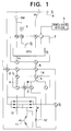
- Fig. 1 shows in a diagrammatic form an arrangement of a charge control system for an internal combustion engine according to a first embodiment of this invention
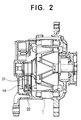
- Fig. 2 shows in cross section a construction of a generator used in the charge control system
- a charge control system for an internal combustion engine (which will hereinafter be referred to as a charge control system) is equipped with a generator 1 driven by an internal combustion engine of a motor vehicle such as a car, a computer unit 2 for controlling the output of the generator 1, a vehicle state detector 3 for detecting the operational states (for example, a battery temperature, vehicle speed, and throttle opening degree) of the motor vehicle necessary for calculations the computer unit 2 performs, and a battery 4 charged by the output of the generator 1.
- a charge control system for an internal combustion engine (which will hereinafter be referred to as a charge control system) is equipped with a generator 1 driven by an internal combustion engine of a motor vehicle such as a car, a computer unit 2 for controlling the output of the generator 1, a vehicle state detector 3 for detecting the
- the generator 1 is provided with a three-phase armature coil 11 and a field coil 12, the output thereof being made to increase and decrease in such a way that a field current If flowing through the field coil 12 is controlled with an electronic switching device operable with a small or limited current and driven in accordance with a drive signal from the computer unit 2.
- the output of the generator 1 is rectified with a built-in three-phase full-wave rectifier 13.
- the electronic switching device is composed of a transistor Tr which, as shown in Fig. 2, is mounted on an IC substrate 14 disposed in the vicinity of a brush 21 in a bracket 22.
- the IC substrate 14 has a commutation diode D and a resistor R for protecting the computer unit 2 against a short-circuit current.
- the computer unit 2 includes a microcomputer CPU which outputs a drive signal for operating the transistor Tr on the basis of the detection results of the vehicle state detecting 3, a voltage Vb of the battery, and the like. This microcomputer CPU also executes the fuel injection control and the ignition timing control for the motor vehicle, whereas the description of these operations will be omitted because of being not directly associated with this invention. Moreover, the computer unit 2 receives, as an input, the output (Vp) of the generator 1, corresponding to one phase, through a smoothing circuit, not shown. On the basis of this input, the computer unit 2 checks whether or not the battery is normally charged with the output of the generator 1, and further executes a charge display control operation, i.e., turns a charge (CHG) lamp 5 on to give an alarm. The generator 1 and the computer unit 2 are in a coupled relation to each other through a lead wire 6. Further, the computer unit 2 comes into connection with the battery 4 through a main switch SW.
- This operation begins with a step S1 to detect operational states of a motor vehicle using the vehicle state detector 3, then followed by a step S2 to determine a target voltage Vreg for the generator 1 on the basis of the detection results in the step S1.
- the operational flow advances to a step S3 to detect the battery voltage Vb and then proceeds to a step S4 to compare the detected battery voltage Vb with the determined target voltage Vreg in the step S2. If Vreg > Vb, the operational flow goes to a step S5 to issue a high-level signal to turn the transistor Tr on.
- step S6 the operational flow advances to a step S6 to produce a low-level signal which in turn, causes the transistor Tr to get into an off state.
- control is made for the field current If flowing through the field coil 12.
- step S7 a step S7 follows in order to check whether the output Vp, corresponding to one phase, of the armature coil 11 of the generator 1 is present within a predetermined range.
- the operational flow proceeds to a step S8 wherein, assumed that the output of the generator 1 is sufficient to charge the battery 4, the charge lamp 5 constituting the alarm turns off, and the operation terminates.
- the operational flow goes to a step S9 in which the output of the generator 1 is considered to be abnormal so as to stop the normal charge to the battery 4, and the charge lamp 5 exhibits an alarm, before the operation completes.
- the transistor Tr driven in accordance with the calculation results of the computer unit 2 is incorporated into the generator 1 so as to execute the control of the field current If, the output of the generator 1 is controllable with a limited current (approximately 10 mA) representative of a signal from the computer unit 2.
- a limited current approximately 10 mA
- This arrangement permits the electromagnetic noise to be reduced up to a level which hardly suffers from a problem, with the result that the countermeasures such as the provision of a noise preventing filter for suppressing the electromagnetic noise becomes unnecessary, which can avoid the increase in manufacturing cost and which makes it unnecessary to need much time and work for confirmation of its effects in a development stage, with an exceedingly decreased number of manufacturing steps.
- the transistor Tr built in the generator 1 can be positioned at an upstream side of a lead wire 66 for connection between a terminal C of the generator and a terminal C of the computer unit 2, and hence, even if these terminals C and the lead wire 6 are grounded for some reason, the transistor Tr turns off irrespective of the drive signal from the computer unit 2 to inhibit the flow of the field current If, with the result that the generator 1 stops its power generation to prevent the overcharge to the battery 4.
- a drive duty ratio Df is calculated by an equation, as will be described later, as a function of a deviation ⁇ V in voltage between the target voltage Vreg and the battery voltage Vb in accordance with a PID control method so that the transistor Tr is driven with a predetermined fixed frequency, for example, 200 Hz, of drive duty signal.
- a predetermined fixed frequency for example, 200 Hz
Landscapes
- Engineering & Computer Science (AREA)
- Power Engineering (AREA)
- Control Of Eletrric Generators (AREA)
- Control Of Charge By Means Of Generators (AREA)
Applications Claiming Priority (3)
| Application Number | Priority Date | Filing Date | Title |
|---|---|---|---|
| JP76346/95 | 1995-03-31 | ||
| JP7076346A JPH08275405A (ja) | 1995-03-31 | 1995-03-31 | 内燃機関用充電制御装置 |
| JP7634695 | 1995-03-31 |
Publications (2)
| Publication Number | Publication Date |
|---|---|
| EP0735641A1 true EP0735641A1 (fr) | 1996-10-02 |
| EP0735641B1 EP0735641B1 (fr) | 2001-07-11 |
Family
ID=13602806
Family Applications (1)
| Application Number | Title | Priority Date | Filing Date |
|---|---|---|---|
| EP95119637A Expired - Lifetime EP0735641B1 (fr) | 1995-03-31 | 1995-12-13 | Système de commande de charge pour utilisation dans un moteur à combustion interne |
Country Status (6)
| Country | Link |
|---|---|
| US (1) | US5760486A (fr) |
| EP (1) | EP0735641B1 (fr) |
| JP (1) | JPH08275405A (fr) |
| KR (1) | KR100286247B1 (fr) |
| CN (1) | CN1045035C (fr) |
| DE (1) | DE69521679T2 (fr) |
Cited By (4)
| Publication number | Priority date | Publication date | Assignee | Title |
|---|---|---|---|---|
| EP1118492A3 (fr) * | 2000-01-20 | 2002-05-08 | Nissan Motor Co., Ltd. | Dispositif de commande de véhicule |
| EP1109284A3 (fr) * | 1999-12-16 | 2003-02-26 | Denso Corporation | Dispositif de commande d'un générateur alternatif d'un véhicule et connecteur |
| EP2453546A1 (fr) * | 2010-11-12 | 2012-05-16 | Fiat Powertrain Technologies S.p.A. | Système électrique automobile fourni avec un système de contrôle électronique d'alternateur |
| CN103684159A (zh) * | 2013-12-05 | 2014-03-26 | 中国北车集团大连机车车辆有限公司 | 防止内燃机车辅助发电电路过压的控制方法 |
Families Citing this family (11)
| Publication number | Priority date | Publication date | Assignee | Title |
|---|---|---|---|---|
| JP3371691B2 (ja) * | 1996-06-25 | 2003-01-27 | 日産自動車株式会社 | ハイブリッド車の発電制御装置 |
| JP3556871B2 (ja) * | 1999-11-11 | 2004-08-25 | 三菱電機株式会社 | オルタネータの制御装置 |
| JP3598975B2 (ja) * | 2001-01-19 | 2004-12-08 | 日産自動車株式会社 | 燃料電池自動車の制御装置 |
| JP3839382B2 (ja) * | 2002-09-13 | 2006-11-01 | 本田技研工業株式会社 | 車載蓄電装置の制御装置 |
| CN1292937C (zh) * | 2004-06-15 | 2007-01-03 | 浙江大学 | 一种轻型交通工具的集成电力驱动系统 |
| CN1295099C (zh) * | 2004-06-15 | 2007-01-17 | 嘉兴市富鑫龙进出口有限公司 | 一种轻型交通工具的燃气-电动集成混合动力系统 |
| US7239113B2 (en) * | 2005-05-03 | 2007-07-03 | Caterpillar Inc | Method for reducing undesired currents in an electrical power generation system |
| JP4670656B2 (ja) * | 2006-01-24 | 2011-04-13 | 株式会社デンソー | 車両の電力供給装置 |
| KR101441126B1 (ko) | 2007-09-10 | 2014-09-18 | 삼성에스디아이 주식회사 | 이차전지의 급속 충전 장치 및 방법 |
| CN101397969B (zh) * | 2007-09-25 | 2010-12-08 | 三菱电机株式会社 | 内燃机控制装置 |
| CN102097995A (zh) * | 2010-12-28 | 2011-06-15 | 重庆长安汽车股份有限公司 | 一种具有监控功能的交流发电机控制系统 |
Citations (5)
| Publication number | Priority date | Publication date | Assignee | Title |
|---|---|---|---|---|
| DE2643612A1 (de) * | 1975-09-29 | 1977-04-28 | Hitachi Ltd | Wechselstromgenerator mit einbau- spannungsregler |
| US4651081A (en) * | 1985-02-25 | 1987-03-17 | Mitsubishi Denki Kabushiki Kaisha | Control apparatus for vehicular charging generator |
| EP0438884A1 (fr) * | 1990-01-17 | 1991-07-31 | Hitachi, Ltd. | Appareil de contrôle pour générateur électrique |
| DE4108751A1 (de) * | 1990-03-19 | 1991-09-26 | Hitachi Ltd | Steuerungssystem fuer fahrzeuglichtmaschine |
| DE4321970A1 (de) * | 1992-07-03 | 1994-01-05 | Hitachi Ltd | Steuervorrichtung für einen Batterielade-AC-Generator zur Verwendung in einem Kraftfahrzeug |
Family Cites Families (5)
| Publication number | Priority date | Publication date | Assignee | Title |
|---|---|---|---|---|
| FR2525039B1 (fr) * | 1982-04-13 | 1989-08-04 | Mitsubishi Electric Corp | Dispositif de commande d'un circuit de charge de batterie d'accumulateurs d'un vehicule |
| FR2528583B1 (fr) * | 1982-06-11 | 1987-03-06 | Mitsubishi Electric Corp | Dispositif de diagnostic de circuit de charge |
| JPS6067133A (ja) * | 1983-09-26 | 1985-04-17 | Kohjin Co Ltd | ポリフッ化ビニリデン系二軸延伸フィルム及びその製造法 |
| JPH082152B2 (ja) * | 1985-06-12 | 1996-01-10 | 日本電装株式会社 | 車両充電発電機の電圧調整装置 |
| US5216350A (en) * | 1991-06-10 | 1993-06-01 | Ford Motor Company | Method and system for controlling an alternator |
-
1995
- 1995-03-31 JP JP7076346A patent/JPH08275405A/ja active Pending
- 1995-12-08 US US08/569,983 patent/US5760486A/en not_active Expired - Lifetime
- 1995-12-13 EP EP95119637A patent/EP0735641B1/fr not_active Expired - Lifetime
- 1995-12-13 DE DE69521679T patent/DE69521679T2/de not_active Expired - Lifetime
-
1996
- 1996-03-26 KR KR1019960008398A patent/KR100286247B1/ko not_active Expired - Lifetime
- 1996-03-28 CN CN96100598A patent/CN1045035C/zh not_active Expired - Fee Related
Patent Citations (5)
| Publication number | Priority date | Publication date | Assignee | Title |
|---|---|---|---|---|
| DE2643612A1 (de) * | 1975-09-29 | 1977-04-28 | Hitachi Ltd | Wechselstromgenerator mit einbau- spannungsregler |
| US4651081A (en) * | 1985-02-25 | 1987-03-17 | Mitsubishi Denki Kabushiki Kaisha | Control apparatus for vehicular charging generator |
| EP0438884A1 (fr) * | 1990-01-17 | 1991-07-31 | Hitachi, Ltd. | Appareil de contrôle pour générateur électrique |
| DE4108751A1 (de) * | 1990-03-19 | 1991-09-26 | Hitachi Ltd | Steuerungssystem fuer fahrzeuglichtmaschine |
| DE4321970A1 (de) * | 1992-07-03 | 1994-01-05 | Hitachi Ltd | Steuervorrichtung für einen Batterielade-AC-Generator zur Verwendung in einem Kraftfahrzeug |
Cited By (8)
| Publication number | Priority date | Publication date | Assignee | Title |
|---|---|---|---|---|
| EP1109284A3 (fr) * | 1999-12-16 | 2003-02-26 | Denso Corporation | Dispositif de commande d'un générateur alternatif d'un véhicule et connecteur |
| US6700357B2 (en) | 1999-12-16 | 2004-03-02 | Denso Corporation | Electromagnetic wave noise entry inhibiting connector for vehicular AC generator control device |
| EP1118492A3 (fr) * | 2000-01-20 | 2002-05-08 | Nissan Motor Co., Ltd. | Dispositif de commande de véhicule |
| EP2453546A1 (fr) * | 2010-11-12 | 2012-05-16 | Fiat Powertrain Technologies S.p.A. | Système électrique automobile fourni avec un système de contrôle électronique d'alternateur |
| WO2012062926A3 (fr) * | 2010-11-12 | 2013-01-10 | Fiat Powertrain Technologies S.P.A. | Système électrique automobile doté d'un système de commande électronique d'alternateur |
| US9168881B2 (en) | 2010-11-12 | 2015-10-27 | Fiat Group Automobiles S.P.A. | Automotive electrical system provided with an alternator electronic control system |
| CN103684159A (zh) * | 2013-12-05 | 2014-03-26 | 中国北车集团大连机车车辆有限公司 | 防止内燃机车辅助发电电路过压的控制方法 |
| CN103684159B (zh) * | 2013-12-05 | 2016-06-29 | 中国北车集团大连机车车辆有限公司 | 防止内燃机车辅助发电电路过压的控制方法 |
Also Published As
| Publication number | Publication date |
|---|---|
| DE69521679D1 (de) | 2001-08-16 |
| EP0735641B1 (fr) | 2001-07-11 |
| CN1137699A (zh) | 1996-12-11 |
| KR960036245A (ko) | 1996-10-28 |
| JPH08275405A (ja) | 1996-10-18 |
| HK1001819A1 (en) | 1998-07-10 |
| US5760486A (en) | 1998-06-02 |
| DE69521679T2 (de) | 2002-04-25 |
| CN1045035C (zh) | 1999-09-08 |
| KR100286247B1 (ko) | 2001-04-16 |
Similar Documents
| Publication | Publication Date | Title |
|---|---|---|
| US5760486A (en) | Charge control system for use in internal combustion engine | |
| KR100220898B1 (ko) | 발전기의 제어장치 및 제어방법과 그것을 응용한 차량용 발전기의 제어장치 및 제어방법 | |
| EP0691726B1 (fr) | Chargeur pour un véhicule | |
| US7053500B2 (en) | Automotive electric power unit | |
| JP3262571B2 (ja) | オルタネータ制御装置 | |
| US6534959B1 (en) | Voltage sensing for automotive voltage regulator | |
| KR101035362B1 (ko) | 차량용 배터리 충전 장치 및 차량용 발전기의 발전 동작 제어 장치 | |
| EP0724321B1 (fr) | Appareil de commande d'un alternateur de véhicule à moteur | |
| US6469475B2 (en) | Method and apparatus for detecting a disconnection in the charge line between a generator and an electric battery in a motor vehicle | |
| JP2986905B2 (ja) | 充電発電機の制御装置 | |
| KR20020066407A (ko) | 연료효율의 최적화와 배터리 모니터링을 위한 자동차용알터네이터 및 그 방법 | |
| US5122723A (en) | Charging control apparatus for vehicles | |
| US4608639A (en) | Charge control microcomputer device for vehicle | |
| JPH03502873A (ja) | 自動車用三相発電機の制御方法 | |
| EP0448064B1 (fr) | Système pour recharger la batterie d'un véhicule à moteur | |
| US4803377A (en) | Starter motor control device for engines | |
| HK1001819B (en) | Charge control system for use in internal combustion engine | |
| KR19990022002A (ko) | 제어된 전압의 형성을 위한 장치 및 방법 | |
| JPH0667132B2 (ja) | ゼネレータ用電圧レギユレータ | |
| KR100270788B1 (ko) | 차량용 발전기의 제어장치 | |
| JP3846012B2 (ja) | 車両用発電機の電圧制御装置 | |
| JP2918755B2 (ja) | 充電制御装置 | |
| JP3021689B2 (ja) | 車両用交流発電機の電圧制御装置 | |
| JPH0638398A (ja) | 車輌用交流発電機の発電制御システム | |
| JPH0543252Y2 (fr) |
Legal Events
| Date | Code | Title | Description |
|---|---|---|---|
| PUAI | Public reference made under article 153(3) epc to a published international application that has entered the european phase |
Free format text: ORIGINAL CODE: 0009012 |
|
| AK | Designated contracting states |
Kind code of ref document: A1 Designated state(s): DE FR GB IT |
|
| 17P | Request for examination filed |
Effective date: 19961007 |
|
| 17Q | First examination report despatched |
Effective date: 19980430 |
|
| GRAG | Despatch of communication of intention to grant |
Free format text: ORIGINAL CODE: EPIDOS AGRA |
|
| GRAG | Despatch of communication of intention to grant |
Free format text: ORIGINAL CODE: EPIDOS AGRA |
|
| GRAH | Despatch of communication of intention to grant a patent |
Free format text: ORIGINAL CODE: EPIDOS IGRA |
|
| GRAH | Despatch of communication of intention to grant a patent |
Free format text: ORIGINAL CODE: EPIDOS IGRA |
|
| GRAA | (expected) grant |
Free format text: ORIGINAL CODE: 0009210 |
|
| AK | Designated contracting states |
Kind code of ref document: B1 Designated state(s): DE FR GB IT |
|
| ITF | It: translation for a ep patent filed | ||
| REF | Corresponds to: |
Ref document number: 69521679 Country of ref document: DE Date of ref document: 20010816 |
|
| REG | Reference to a national code |
Ref country code: GB Ref legal event code: 727 |
|
| REG | Reference to a national code |
Ref country code: GB Ref legal event code: 727A |
|
| ET | Fr: translation filed | ||
| REG | Reference to a national code |
Ref country code: GB Ref legal event code: IF02 |
|
| REG | Reference to a national code |
Ref country code: GB Ref legal event code: 727B |
|
| PLBE | No opposition filed within time limit |
Free format text: ORIGINAL CODE: 0009261 |
|
| STAA | Information on the status of an ep patent application or granted ep patent |
Free format text: STATUS: NO OPPOSITION FILED WITHIN TIME LIMIT |
|
| 26N | No opposition filed | ||
| PGFP | Annual fee paid to national office [announced via postgrant information from national office to epo] |
Ref country code: GB Payment date: 20071212 Year of fee payment: 13 Ref country code: FR Payment date: 20071210 Year of fee payment: 13 |
|
| PGFP | Annual fee paid to national office [announced via postgrant information from national office to epo] |
Ref country code: IT Payment date: 20081222 Year of fee payment: 14 |
|
| GBPC | Gb: european patent ceased through non-payment of renewal fee |
Effective date: 20081213 |
|
| REG | Reference to a national code |
Ref country code: FR Ref legal event code: ST Effective date: 20090831 |
|
| PG25 | Lapsed in a contracting state [announced via postgrant information from national office to epo] |
Ref country code: GB Free format text: LAPSE BECAUSE OF NON-PAYMENT OF DUE FEES Effective date: 20081213 |
|
| PG25 | Lapsed in a contracting state [announced via postgrant information from national office to epo] |
Ref country code: FR Free format text: LAPSE BECAUSE OF NON-PAYMENT OF DUE FEES Effective date: 20081231 |
|
| PG25 | Lapsed in a contracting state [announced via postgrant information from national office to epo] |
Ref country code: IT Free format text: LAPSE BECAUSE OF NON-PAYMENT OF DUE FEES Effective date: 20091213 |
|
| PGFP | Annual fee paid to national office [announced via postgrant information from national office to epo] |
Ref country code: DE Payment date: 20141209 Year of fee payment: 20 |
|
| REG | Reference to a national code |
Ref country code: DE Ref legal event code: R071 Ref document number: 69521679 Country of ref document: DE |