EP0735672A2 - Transducteur double à ondes acoustiques de surface pour filtre double, notamment pour récepteurs de télévision - Google Patents
Transducteur double à ondes acoustiques de surface pour filtre double, notamment pour récepteurs de télévision Download PDFInfo
- Publication number
- EP0735672A2 EP0735672A2 EP96104184A EP96104184A EP0735672A2 EP 0735672 A2 EP0735672 A2 EP 0735672A2 EP 96104184 A EP96104184 A EP 96104184A EP 96104184 A EP96104184 A EP 96104184A EP 0735672 A2 EP0735672 A2 EP 0735672A2
- Authority
- EP
- European Patent Office
- Prior art keywords
- transducer
- areas
- curve
- meander
- interdigital
- Prior art date
- Legal status (The legal status is an assumption and is not a legal conclusion. Google has not performed a legal analysis and makes no representation as to the accuracy of the status listed.)
- Granted
Links
Images

Classifications
-
- H—ELECTRICITY
- H04—ELECTRIC COMMUNICATION TECHNIQUE
- H04N—PICTORIAL COMMUNICATION, e.g. TELEVISION
- H04N5/00—Details of television systems
- H04N5/44—Receiver circuitry for the reception of television signals according to analogue transmission standards
-
- H—ELECTRICITY
- H03—ELECTRONIC CIRCUITRY
- H03H—IMPEDANCE NETWORKS, e.g. RESONANT CIRCUITS; RESONATORS
- H03H9/00—Networks comprising electromechanical or electro-acoustic elements; Electromechanical resonators
- H03H9/46—Filters
- H03H9/64—Filters using surface acoustic waves
-
- H—ELECTRICITY
- H03—ELECTRONIC CIRCUITRY
- H03H—IMPEDANCE NETWORKS, e.g. RESONANT CIRCUITS; RESONATORS
- H03H9/00—Networks comprising electromechanical or electro-acoustic elements; Electromechanical resonators
- H03H9/02—Details
- H03H9/125—Driving means, e.g. electrodes, coils
- H03H9/145—Driving means, e.g. electrodes, coils for networks using surface acoustic waves
- H03H9/14517—Means for weighting
- H03H9/1452—Means for weighting by finger overlap length, apodisation
-
- H—ELECTRICITY
- H03—ELECTRONIC CIRCUITRY
- H03H—IMPEDANCE NETWORKS, e.g. RESONANT CIRCUITS; RESONATORS
- H03H9/00—Networks comprising electromechanical or electro-acoustic elements; Electromechanical resonators
- H03H9/46—Filters
- H03H9/64—Filters using surface acoustic waves
- H03H9/6423—Means for obtaining a particular transfer characteristic
- H03H9/6426—Combinations of the characteristics of different transducers
-
- H—ELECTRICITY
- H03—ELECTRONIC CIRCUITRY
- H03H—IMPEDANCE NETWORKS, e.g. RESONANT CIRCUITS; RESONATORS
- H03H9/00—Networks comprising electromechanical or electro-acoustic elements; Electromechanical resonators
- H03H9/70—Multiple-port networks for connecting several sources or loads, working on different frequencies or frequency bands, to a common load or source
- H03H9/72—Networks using surface acoustic waves
-
- H—ELECTRICITY
- H03—ELECTRONIC CIRCUITRY
- H03H—IMPEDANCE NETWORKS, e.g. RESONANT CIRCUITS; RESONATORS
- H03H2250/00—Indexing scheme relating to dual- or multi-band filters
Definitions
- the present invention relates to a double converter, suitable for a double filter, as is to be used in particular in television receivers as the only channel filter instead of the two channel filters used up to now.
- the state of the art uses television channel filters in television receivers which, together with the high-frequency signal from a tunable oscillator, serve for the selection of a desired television channel to be made by the television viewer. It has been known for decades to use such television filters which are constructed using surface wave technology.
- the television signals to be received from the television channels assigned to the individual television channels have certain standardized characteristics. However, this standardization is not even uniform across Europe, e.g. due to the different channel bandwidths, for example in Germany and France. There is also a standardized, predetermined pass-through behavior of the channel filters of different standards.
- two different surface acoustic wave filters are used as the respective channel filters of one and the other standard.
- Such two channel filters are known to be arranged side by side on a substrate plate. Essentially, however, almost as much substrate material is required as is required for two separate filters taken together.
- the well-known combination of two channel filters for different standards on one about twice the size
- the substrate body essentially serves to simplify the assembly of the filter and the like.
- the filter according to the invention has made progress, in particular with regard to saving substrate material, without having to give up other advantages of the prior art.
- the invention provides a double converter, suitable for a double filter, as specified in claim 1 or claim 2, and further refinements and developments of the invention emerge from the subclaims.
- a double filter with a double converter according to the invention has the property that it can meet the requirements of two different television standards combined in a single filter as a result of its construction and filter design according to the invention as a channel filter.
- the filter of the prior art shown in FIG. 2 comprises two interdigital transducers 12 and 13 on piezoelectric material, in particular a substrate 11. As shown, these two transducers are placed next to one another on the substrate. They serve as input converters with inputs E1 and E2 for television input signals from two different ones Television standards. The entire input signal of the antenna can be switched to either one input E1 or the other input E2 via a device-internal electronic switch which is arranged in advance of the inputs E1 and E2.
- One converter 12 is designed for the input signal of one standard and the other converter 13 is designed for the input signal of the other standard.
- One transducer 12 generates an acoustic wave in accordance with its transducer structure. This is converted back into an electrical signal in the common output converter 14 for both input filters 12, 13, which has the form required by the receiving device that the television picture of the selected channel can be correctly displayed on the screen. This applies analogously to the input signal at the input E2 of the second converter 13.
- FIG. 1 shows a schematic diagram of a double filter with a converter according to the invention with the inputs E1 and E2, which can in turn be switched, in the "double function" as input converter 2 and output converter 4.
- These components of the filter according to the invention are on one Piezoelectric substrate 1 applied.
- this plate 1 can be considerably smaller than the substrate plate 11 of the known filter combination according to FIG. 2.
- the size / amount of the single crystalline substrate material used is a significant cost factor for such a filter as the invention is concerned.
- Another important cost factor is the hermetically sealed housing of the filter. A cheaper substrate is sufficient for a smaller substrate made possible by the invention smaller housing without which, and this is also significant, higher insertion loss would be accepted.
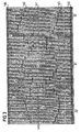
- FIG. 3 shows an example of an essential section of the finger structure or the design of an input converter 2 of a filter according to the invention, which e.g. for television receivers for the reception of television channels of various, e.g. German and French standards can be used advantageously.
- the design according to the invention of the structure of the input converter 2 of a filter can be described functionally divided into three parts. These extend adjacent in the main direction of propagation of the acoustic wave.
- the fingers of the structure are oriented at right angles to this axial direction of propagation.
- the middle portion 31 of the transducer 2 comprises the portion m, which is important for the integral damping behavior of the filter according to the invention, with relatively strong finger overlaps, in which the predominant degree of the conversion of the electrical signal into the surface acoustic wave takes place. To a large extent, this middle portion 31 corresponds to that which is also present in a known converter 12, 13.
- the two portions 32 and 32 'adjoining the portion 31 serve primarily to shape the passage curve, as is in itself well known.
- the filter design of such an input converter is also created with the aid of available optimization algorithms, which, however, are given different boundary conditions in the invention. This then leads to the new filter design, which differs significantly from the prior art.
- FIG. 4 shows the meandering structures of the finger overlaps of FIG. 3 as they result or are present in the middle portion 31 and the two edge portions 32 and 32 'of the design of a "double-function" input converter provided according to the invention.
- the area m is that of the strong overlaps of the digitally arranged transducer fingers.
- a and a ' denote regions of transducer fingers which are in portions 32 and 32' of FIG. 3.
- the transducer fingers of area a each have relatively small finger overlap lengths with the further transducer fingers of transducer 2 provided here in areas b and c. The same applies to the overlap of the transducer fingers of area a 'with the transducer fingers of areas b' and c '.
- a special feature of the invention are also the transducer fingers of the areas d and e in the portion 31 of the dual-function input transducer 2 according to the invention which is in the middle. However, only a single such area (d or e) can be provided in the invention. To create the design of the converter according to the invention, however, it can be advantageous to specify two such areas d and e as in the example.
- busbars or busbars are entered, which serve for the respective potential supply of the transducer fingers of the individual areas.
- busbar 41 By a corresponding potential connection to the busbar 41, all transducer fingers of area a can be acted upon by this potential.
- the respective busbars of areas b, b 'and c, c' are designated by 42 and 43.
- Areas d and e include busbars 44 and 45, respectively.
- meandering curves the peculiarities of the multiple meandering polygon courses present in a transducer according to the invention is particularly suitable previously mentioned meander structure.
- a peculiarity of the invention is that a transducer according to the invention has at least one further meander curve 64 and / or 65 in its (essentially) central region 31 already mentioned above in addition to the meander curve 61 of the central region m.
- the example of FIGS. 3 and 4 comprises three such meandering curves 61, 64 and 65 in the central region 31, which, as can be seen particularly from FIG. 4, relate with their main directions 361, 364 and 365 essentially in the direction of the main direction of propagation x of the wave positioned laterally next to one another in this direction of propagation.
- the meandering structure of the design of the transducer 2 according to the invention is the presence of at least one branching point 51, 51 'in the course (or at one or both ends) of the meandering curve 61 4, the meandering curve 61 continues in the region 32 from the branching point 51 in two further meandering curves 62 and 63.
- the meandering curve 61 continues at the branching point 51 ′ with the meandering curves 62 ′ and 63 ′.
- the input converter 2 of a filter according to the invention has a meandering structure with at least one such branch point 51 or 51 '.
- the meander curve 62 indicates the overlaps of the fingers of area a with those of area b and the meander curve 63 those of area a with those of area c.
- the meandering curves 62 ', 63' correspondingly mark the overlaps of the fingers of area a 'with those of area b' or c '.
- a meandering structure corresponding to FIG. 4 has a substantially different appearance.
- both the input signal of one standard and the input signal of the other standard serve as a boundary condition for the application of the optimization algorithm.
- the overlaps with the fingers of the area serve to further adapt the central area m to the one standard, ie as a filter function of the channel filter prescribed by the one standard d.
- the area e has corresponding meaning for the other transmission function, for example as a channel filter of the other standard.
- the areas d and e have an important function as adaptation elements for the filter according to the invention.
- a converter 2 according to the invention with the double function according to the invention is operated in practice, for example and advantageously as follows.
- the filter of the one transmission function for example as the television channel filter of the one standard
- the transducer fingers of the areas a, a ', d and e are set to a predetermined potential, e.g. to ground potential.
- the areas c, c ' are additionally connected to the aforementioned areas and the transducer fingers of the area b, b' remain as the opposite pole for the connection of the one input signal I.
- areas a, a ', d and e remain interconnected, e.g.
- the transducer fingers of area b, b ' are now connected.
- One half of the transducer fingers of the area m is connected to the area b, b ', the other half to the area c, c'.
- Areas b, b 'on the one hand and c, c' on the other hand in particular the respective portion of the area that lies between the strong overlaps of area m and area d on the one hand or area e on the other, available range of variation.
- the areas d and e are also to be understood as areas with such overlaps which adapt the common double-acting converter of the double filter to the one transfer function on the one hand and to the other transfer function on the other.
- the respective area d or e of these correction overlaps is made for the respective transfer function I, II together with the respective half of the transducer fingers of the area m with one or with the applied to another input signal.
- a double filter designed with the invention is produced using the usual methods of developing and producing surface acoustic wave filters.
- the electrical potential connections 141 to 145 for the regions a to e or their busbars 41 to 45 are preferably also provided on the substrate plate 1. These connections are contacted in a known manner with very thin bond wires or the like.
- the connection 142 of the busbar 42 or the area b, b ' is the input E1 for the one transfer function or for the one input signal I.
- the areas a, a', d and e, ie the busbars 41, 41 ', 44 and 45, are always at the same potential , preferably to ground. If the filter is supplied with the input signal E1, the other input E2 must be connected to the potential of the areas a, a ', d and e. Becomes conversely, input E2 is supplied with the (other) input signal, input E1 is to be connected to the potential of these further four areas.
- a switch function which is preferably carried out electronically, is additionally to be provided in the invention as external operating means of the double filter.
- An example of a further mode of operation of the converter is for a transmission function to apply the first input signal I to the interconnected areas c, c 'and a' and the areas a, b, b ', d and e connected to each other to the same potential, e.g. Mass, to lay.
- the second input signal II is applied to the areas b, b 'and a and the areas a', c, c ', d and e are at the same potential, e.g. Mass, lived.
- the overlaps of area d and that of area e with the respectively adjacent area are significantly involved for one and for the other of the transfer functions of the converter according to the invention with a double function.
- the filter according to the invention can also be operated symmetrically, i.e. one pole of the respective input signal is connected as indicated above and the other pole is connected to the "same potential" connection.
- the invention thus leads to a single-track inline filter and is preferably suitable as an advantageous substitution of two channel filters of known designs (FIG. 2).
- the converter according to the invention with a double function as an input converter of a filter using surface wave technology has been described above.
- the transducer Depending on which input signal the If the transducer is fed to its inputs E1 and E2, the transducer according to the invention generates a unique, ie in each case the same acoustic wave in the substrate, which is converted into the same electrical output signal in the output transducer.
- the inputs E1 and E2 are the respective combinations of the connections to the individual areas a to e, as described above.
- the transducer according to the invention can also be used to generate the same electrical (output) signal in each case, with this transducer according to the invention acting as an output transducer being alternatively supplied with two different acoustic waves over time.
- An example of this is a filter according to FIG. 1, in which a certain predetermined electrical signal is then fed to the converter 4 as an input signal, this converter generates an acoustic wave in the substrate 1 and two different electrical signals in the converter 2, which is then an output converter which are then output signals.
- These two different signals can in turn be taken alternatively in time from the converter 2, namely one signal when one connection combination is present and the other signal when the other connection combination is present, namely as these connection combinations of the modes of operation described above are specified.
- surface waves are not only to be understood as acoustic waves of the type of the Raleigh waves and Bleustein-Gulyaiv waves, but also surface scimming bulk waves (SSB waves), leaky surface waves, low waves and the like waves.
- SSB waves surface scimming bulk waves
Landscapes
- Physics & Mathematics (AREA)
- Acoustics & Sound (AREA)
- Engineering & Computer Science (AREA)
- Multimedia (AREA)
- Signal Processing (AREA)
- Surface Acoustic Wave Elements And Circuit Networks Thereof (AREA)
- Piezo-Electric Or Mechanical Vibrators, Or Delay Or Filter Circuits (AREA)
Applications Claiming Priority (2)
| Application Number | Priority Date | Filing Date | Title |
|---|---|---|---|
| DE19512251A DE19512251C2 (de) | 1995-03-31 | 1995-03-31 | Interdigitalwandler für ein Oberflächenfilter |
| DE19512251 | 1995-03-31 |
Publications (3)
| Publication Number | Publication Date |
|---|---|
| EP0735672A2 true EP0735672A2 (fr) | 1996-10-02 |
| EP0735672A3 EP0735672A3 (fr) | 1997-02-05 |
| EP0735672B1 EP0735672B1 (fr) | 2002-11-27 |
Family
ID=7758534
Family Applications (1)
| Application Number | Title | Priority Date | Filing Date |
|---|---|---|---|
| EP96104184A Expired - Lifetime EP0735672B1 (fr) | 1995-03-31 | 1996-03-15 | Transducteur double à ondes acoustiques de surface pour filtre double, notamment pour récepteurs de télévision |
Country Status (6)
| Country | Link |
|---|---|
| US (1) | US5867075A (fr) |
| EP (1) | EP0735672B1 (fr) |
| JP (1) | JP3806178B2 (fr) |
| KR (1) | KR100425398B1 (fr) |
| CA (1) | CA2173055A1 (fr) |
| DE (2) | DE19512251C2 (fr) |
Families Citing this family (4)
| Publication number | Priority date | Publication date | Assignee | Title |
|---|---|---|---|---|
| DE102004054081A1 (de) | 2004-11-09 | 2006-05-11 | Epcos Ag | Umschaltbares SAW Filter,Filter-Vorrichtung mit dem SAW Filter und Verfahren zum Betreiben des SAW Filters |
| CN101316099B (zh) * | 2008-07-04 | 2010-06-16 | 无锡市好达电子有限公司 | 双通道声表面波滤波器 |
| WO2012055439A1 (fr) | 2010-10-28 | 2012-05-03 | Epcos Ag | Filtre commutable |
| US11621695B2 (en) | 2020-10-02 | 2023-04-04 | RF360 Europe GmbH | Cascaded surface acoustic wave devices with apodized interdigital transducers |
Family Cites Families (12)
| Publication number | Priority date | Publication date | Assignee | Title |
|---|---|---|---|---|
| US4296391A (en) * | 1977-10-28 | 1981-10-20 | Hitachi, Ltd. | Surface-acoustic-wave filter for channel selection system of television receiver |
| JPS5566120A (en) * | 1978-11-13 | 1980-05-19 | Hitachi Ltd | Elastic surface wave device |
| DE3120050A1 (de) * | 1981-05-20 | 1982-12-09 | Licentia Patent-Verwaltungs-Gmbh, 6000 Frankfurt | Zf-verstaerker fuer einen mehrnormen-fernsehempfaenger |
| US4604595A (en) * | 1982-06-16 | 1986-08-05 | Murata Manufacturing Co., Ltd. | Surface acoustic wave device having interdigitated comb electrodes weighted for odd/even response |
| GB2132844A (en) * | 1982-12-22 | 1984-07-11 | Philips Electronic Associated | Surface acoustic wave device |
| US4673901A (en) * | 1984-10-26 | 1987-06-16 | Siemens Aktiengesellschaft | Electrical filter operating with acoustic waves |
| JPS61164317A (ja) * | 1985-01-14 | 1986-07-25 | シーメンス、アクチエンゲゼルシヤフト | 電気的表面弾性波フイルタ |
| KR900008524B1 (ko) * | 1987-08-19 | 1990-11-24 | 삼성전자 주식회사 | 위성수신기의 지대지간섭 제거를 위한 탄성표면파 필터 |
| US4918349A (en) * | 1987-11-13 | 1990-04-17 | Hitachi, Ltd. | Surface acoustic wave device having apodized transducer provided with irregular pitch electrode group |
| ATE85870T1 (de) * | 1988-11-11 | 1993-03-15 | Siemens Ag | Oberflaechenwellenfilter mit aenderbarem durchlassbereich. |
| JPH04196709A (ja) * | 1990-11-28 | 1992-07-16 | Hitachi Ltd | 通過帯域選択装置 |
| JP2738179B2 (ja) * | 1991-08-19 | 1998-04-08 | 日本電気株式会社 | 弾性表面波フィルタ用重みづけ電極 |
-
1995
- 1995-03-31 DE DE19512251A patent/DE19512251C2/de not_active Expired - Fee Related
-
1996
- 1996-03-15 DE DE59609896T patent/DE59609896D1/de not_active Expired - Lifetime
- 1996-03-15 EP EP96104184A patent/EP0735672B1/fr not_active Expired - Lifetime
- 1996-03-28 KR KR1019960008694A patent/KR100425398B1/ko not_active Expired - Fee Related
- 1996-03-29 CA CA002173055A patent/CA2173055A1/fr not_active Abandoned
- 1996-03-29 JP JP10338996A patent/JP3806178B2/ja not_active Expired - Fee Related
- 1996-04-01 US US08/627,773 patent/US5867075A/en not_active Expired - Lifetime
Also Published As
| Publication number | Publication date |
|---|---|
| JPH08288784A (ja) | 1996-11-01 |
| DE59609896D1 (de) | 2003-01-09 |
| US5867075A (en) | 1999-02-02 |
| JP3806178B2 (ja) | 2006-08-09 |
| EP0735672B1 (fr) | 2002-11-27 |
| DE19512251A1 (de) | 1996-10-10 |
| KR100425398B1 (ko) | 2004-06-16 |
| DE19512251C2 (de) | 1997-04-03 |
| EP0735672A3 (fr) | 1997-02-05 |
| CA2173055A1 (fr) | 1996-10-01 |
| KR960036297A (ko) | 1996-10-28 |
Similar Documents
| Publication | Publication Date | Title |
|---|---|---|
| DE69827187T2 (de) | Akustische Oberflächenwellenanordnung mit Nahfeldkopplung und differentiellen Ein- und Ausgängen | |
| DE2846510C2 (fr) | ||
| DE69100625T2 (de) | Akustische oberflächenwellenfilter. | |
| DE4403949A1 (de) | Baukomponente mit piezoelektrischer Resonanz | |
| DE10314153A1 (de) | Oberflächenwellen-Anordnung zur breitbandigen Signalübertragung | |
| DE3723545A1 (de) | Filter fuer elastische oberflaechenwellen | |
| DE2739688A1 (de) | Elektro-akustische vorrichtung mit einem schallfuehrungselement und elektro- akustischen wandlern | |
| DE2542854A1 (de) | Akustisches oberflaechenwellenfilter | |
| EP1266449A1 (fr) | Transducteur interdigital a excitation repartie | |
| EP0735672B1 (fr) | Transducteur double à ondes acoustiques de surface pour filtre double, notamment pour récepteurs de télévision | |
| DE3015241A1 (de) | Bauelement fuer akustische oberflaechenwellen | |
| DE2841892A1 (de) | Oberflaechenwellen-filter | |
| EP0100997B1 (fr) | Dispositif électronique fonctionnant avec des ondes acoustiques réfléchies | |
| DE2610183A1 (de) | Wellenfilter mit akustischer oberflaechenleitung | |
| DE3329057A1 (de) | Koaxialleitungs-, kammleitungs- oder interdigitalfilter mit wenigstens vier resonatoren | |
| DE2615593A1 (de) | Ultraschallkeramikmikrophon | |
| DE10026074B4 (de) | Rekursives OFW-Filter mit geringer Chiplänge | |
| DE1814954C3 (de) | Elektrische Filterweiche, bestehend aus zwei elektromechanischen Filtern mit unterschiedlicher Bandbreite | |
| DE2324004C3 (de) | Fernsteuerungssystem zur Steuerung des Betriebes eines elektrischen Gerätes | |
| EP1266450B1 (fr) | Filtre de resonateur couple en mode transversal a encombrement reduit | |
| DE2532227A1 (de) | Elektromechanische resonanzeinrichtung und ihre verwendung zur filterung von fernsehsignalen | |
| EP0135769B1 (fr) | Convolueur à ondes de surface | |
| DE2054135B2 (de) | Polylithisches kristallbandpassfilter | |
| DE19724255C2 (de) | Transversalmodenresonatorfilter | |
| DE2441500C2 (de) | Wandler für akustische Oberflächenwellen |
Legal Events
| Date | Code | Title | Description |
|---|---|---|---|
| PUAI | Public reference made under article 153(3) epc to a published international application that has entered the european phase |
Free format text: ORIGINAL CODE: 0009012 |
|
| AK | Designated contracting states |
Kind code of ref document: A2 Designated state(s): CH DE FR GB LI |
|
| PUAL | Search report despatched |
Free format text: ORIGINAL CODE: 0009013 |
|
| AK | Designated contracting states |
Kind code of ref document: A3 Designated state(s): CH DE FR GB LI |
|
| 17P | Request for examination filed |
Effective date: 19970703 |
|
| 17Q | First examination report despatched |
Effective date: 19991015 |
|
| RAP1 | Party data changed (applicant data changed or rights of an application transferred) |
Owner name: EPCOS AG |
|
| GRAG | Despatch of communication of intention to grant |
Free format text: ORIGINAL CODE: EPIDOS AGRA |
|
| GRAG | Despatch of communication of intention to grant |
Free format text: ORIGINAL CODE: EPIDOS AGRA |
|
| GRAH | Despatch of communication of intention to grant a patent |
Free format text: ORIGINAL CODE: EPIDOS IGRA |
|
| GRAH | Despatch of communication of intention to grant a patent |
Free format text: ORIGINAL CODE: EPIDOS IGRA |
|
| GRAA | (expected) grant |
Free format text: ORIGINAL CODE: 0009210 |
|
| AK | Designated contracting states |
Kind code of ref document: B1 Designated state(s): CH DE FR GB LI |
|
| REG | Reference to a national code |
Ref country code: GB Ref legal event code: FG4D Free format text: NOT ENGLISH |
|
| REG | Reference to a national code |
Ref country code: CH Ref legal event code: EP |
|
| GBT | Gb: translation of ep patent filed (gb section 77(6)(a)/1977) |
Effective date: 20021209 |
|
| REF | Corresponds to: |
Ref document number: 59609896 Country of ref document: DE Date of ref document: 20030109 |
|
| PG25 | Lapsed in a contracting state [announced via postgrant information from national office to epo] |
Ref country code: LI Free format text: LAPSE BECAUSE OF NON-PAYMENT OF DUE FEES Effective date: 20030331 Ref country code: CH Free format text: LAPSE BECAUSE OF NON-PAYMENT OF DUE FEES Effective date: 20030331 |
|
| ET | Fr: translation filed | ||
| RAP2 | Party data changed (patent owner data changed or rights of a patent transferred) |
Owner name: EPCOS AG |
|
| PLBE | No opposition filed within time limit |
Free format text: ORIGINAL CODE: 0009261 |
|
| STAA | Information on the status of an ep patent application or granted ep patent |
Free format text: STATUS: NO OPPOSITION FILED WITHIN TIME LIMIT |
|
| REG | Reference to a national code |
Ref country code: CH Ref legal event code: PL |
|
| 26N | No opposition filed |
Effective date: 20030828 |
|
| REG | Reference to a national code |
Ref country code: FR Ref legal event code: PLFP Year of fee payment: 20 |
|
| PGFP | Annual fee paid to national office [announced via postgrant information from national office to epo] |
Ref country code: DE Payment date: 20150320 Year of fee payment: 20 |
|
| PGFP | Annual fee paid to national office [announced via postgrant information from national office to epo] |
Ref country code: FR Payment date: 20150319 Year of fee payment: 20 Ref country code: GB Payment date: 20150324 Year of fee payment: 20 |
|
| REG | Reference to a national code |
Ref country code: DE Ref legal event code: R071 Ref document number: 59609896 Country of ref document: DE |
|
| REG | Reference to a national code |
Ref country code: GB Ref legal event code: PE20 Expiry date: 20160314 |
|
| PG25 | Lapsed in a contracting state [announced via postgrant information from national office to epo] |
Ref country code: GB Free format text: LAPSE BECAUSE OF EXPIRATION OF PROTECTION Effective date: 20160314 |