EP0735698A2 - Téléphone portable pliable avec extension de l'écouteur au déploiement du boîtier du téléphone - Google Patents
Téléphone portable pliable avec extension de l'écouteur au déploiement du boîtier du téléphone Download PDFInfo
- Publication number
- EP0735698A2 EP0735698A2 EP96105061A EP96105061A EP0735698A2 EP 0735698 A2 EP0735698 A2 EP 0735698A2 EP 96105061 A EP96105061 A EP 96105061A EP 96105061 A EP96105061 A EP 96105061A EP 0735698 A2 EP0735698 A2 EP 0735698A2
- Authority
- EP
- European Patent Office
- Prior art keywords
- housing
- earphone unit
- telephone set
- portable telephone
- housings
- Prior art date
- Legal status (The legal status is an assumption and is not a legal conclusion. Google has not performed a legal analysis and makes no representation as to the accuracy of the status listed.)
- Withdrawn
Links
Images





Classifications
-
- H—ELECTRICITY
- H04—ELECTRIC COMMUNICATION TECHNIQUE
- H04M—TELEPHONIC COMMUNICATION
- H04M1/00—Substation equipment, e.g. for use by subscribers
- H04M1/02—Constructional features of telephone sets
- H04M1/03—Constructional features of telephone transmitters or receivers, e.g. telephone hand-sets
-
- H—ELECTRICITY
- H04—ELECTRIC COMMUNICATION TECHNIQUE
- H04B—TRANSMISSION
- H04B7/00—Radio transmission systems, i.e. using radiation field
- H04B7/24—Radio transmission systems, i.e. using radiation field for communication between two or more posts
- H04B7/26—Radio transmission systems, i.e. using radiation field for communication between two or more posts at least one of which is mobile
-
- H—ELECTRICITY
- H04—ELECTRIC COMMUNICATION TECHNIQUE
- H04B—TRANSMISSION
- H04B1/00—Details of transmission systems, not covered by a single one of groups H04B3/00 - H04B13/00; Details of transmission systems not characterised by the medium used for transmission
- H04B1/38—Transceivers, i.e. devices in which transmitter and receiver form a structural unit and in which at least one part is used for functions of transmitting and receiving
- H04B1/3827—Portable transceivers
- H04B1/3833—Hand-held transceivers
-
- H—ELECTRICITY
- H04—ELECTRIC COMMUNICATION TECHNIQUE
- H04B—TRANSMISSION
- H04B1/00—Details of transmission systems, not covered by a single one of groups H04B3/00 - H04B13/00; Details of transmission systems not characterised by the medium used for transmission
- H04B1/38—Transceivers, i.e. devices in which transmitter and receiver form a structural unit and in which at least one part is used for functions of transmitting and receiving
- H04B1/3827—Portable transceivers
- H04B1/3833—Hand-held transceivers
- H04B1/3838—Arrangements for reducing RF exposure to the user, e.g. by changing the shape of the transceiver while in use
-
- H—ELECTRICITY
- H04—ELECTRIC COMMUNICATION TECHNIQUE
- H04M—TELEPHONIC COMMUNICATION
- H04M1/00—Substation equipment, e.g. for use by subscribers
- H04M1/02—Constructional features of telephone sets
- H04M1/0202—Portable telephone sets, e.g. cordless phones, mobile phones or bar type handsets
- H04M1/0206—Portable telephones comprising a plurality of mechanically joined movable body parts, e.g. hinged housings
- H04M1/0208—Portable telephones comprising a plurality of mechanically joined movable body parts, e.g. hinged housings characterized by the relative motions of the body parts
- H04M1/0214—Foldable telephones, i.e. with body parts pivoting to an open position around an axis parallel to the plane they define in closed position
Definitions
- This invention relates to a wireless telephone set and, in particular, to an improvement in such a wireless telephone set of a portable type to reduce unfavorable affection against an antenna gain by the head of a user of the telephone set.
- each telephone set belonging to a first group comprises a single housing.
- each telephone set belonging to a second group is of a foldable type and comprises a pair of housings connected through a hinge portion so as to be rotatable around the hinge portion.
- one housing is provided with a telephone microphone or telephone transmitter (hereinafter simply referred to as a microphone) while the other housing is provided with a telephone earphone or telephone receiver (hereinafter simply referred to as an earphone).
- a positional relationship between the two housings can be adjusted to locate the earphone and the microphone in the vicinity of the ear and the mouth of a user, respectively, when he uses the portable telephone set.
- Each of the housings has a confronting surface to be faced to a similar confronting surface of the other housing when the telephone set is folded.
- the microphone, the earphone, and key pads such as number entry keys are arranged on the confronting surfaces.
- the positional relationship between the microphone and the earphone can not be adjusted as desired by the user.
- the microphone, the earphone, and the key pads are always exposed to the external environment.
- an antenna is protruded from a top surface of the housing provided with the earphone.
- the antenna is extended upward in close proximity of the head of the user. Under the influence of the human body, an antenna gain is inevitably decreased.
- a first unit provided with an earphone is rotatably supported by a second unit provided with a microphone.
- An antenna is formed on the second unit provided with the microphone.
- the first unit provided with the earphone is inclined to form a particular angle with respect to an extending direction of the antenna.
- the portable telephone set in Reference 1 is used with the earphone and the microphone located in the vicinity of the ear and the mouth of the user, respectively, the antenna is extended in a diverging direction away from the head of the user.
- the portable telephone set disclosed in Reference 1 is capable of reducing an interference against a radio wave by increasing a distance between the antenna and the user's head.
- the antenna is extended in the diverging direction away from the head of the user, namely, deviated from a direction straight upward from the head.
- the antenna may possibly be put into contact with something present in the surroundings.
- the user In order to avoid the above-mentioned problem, the user must pay close attention to assure that the antenna, particularly in its top end, is not brought into unfavorable contact with something.
- the earphone is rotatable around a part of the housing provided with the microphone. This makes it possible to protrude the earphone apart from the housing provided with the microphone.
- the antenna is relatively separated from the head of the user. It is therefore possible to reduce such an interference against transmission/reception of a radio wave that is caused by the user's head present in close proximity of the antenna.
- a portable telephone set of a foldable type comprises a first housing with a microphone unit contained therein, a hinge portion supporting one side of the first housing, a second housing having one side supported by the hinge portion so that the second housing is rotatable around the hinge portion within a movable range defined by the hinge portion to be unfolded and folded with respect to the first housing, an earphone unit mounted in the second housing to be exposed outside through a confronting surface of the second housing to be faced to that of the first housing when the first and the second housings are folded, the earphone unit being retracted and received in the second housing when the first and the second housings are folded, the earphone unit partially projecting from the second housing when the first and the second housings are unfolded, and an antenna fixed on a side surface of the second housing that is located opposite to another side surface adjacent to the hinge portion.
- the earphone unit jumps up from the housing in a direction away from the antenna when the portable telephone set is used or unfolded.
- the antenna is extended in a direction substantially straight upward from the head of a user. Accordingly, the antenna is undesiredly brought into contact with something around the head of the user with a reduced possibility.
- the earphone unit automatically jumps up from the housing when the user unfolds the portable telephone set. Accordingly, the user need not perform an additional operation for protruding the earphone unit.
- a portable telephone set of a foldable type comprises a first or lower housing and a second or upper housing connected through a hinge portion.
- an earphone unit jumps up from the upper housing.
- the earphone unit having jumped up is pushed by the lower housing and received in the upper housing.
- the term “earphone unit” represents a combination of the earphone and an earphone case in which the earphone is contained.
- the “earphone” represents an electromechanical transducer for converting an electric signal into a mechanical action.
- the term “microphone unit” represents a combination of a microphone and a microphone case in which the microphone is received.
- the “microphone” represents an electromechanical transducer for converting a mechanical action into an electric signal.
- the term "confronting surface” is used to represent a surface of each housing to be faced to that of the other housing when the housings are folded.
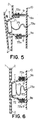
- a portable telephone set of a foldable type according to a first embodiment of this invention has a structure shown in Figs. 1 through 3.
- the portable telephone set comprises a first or lower housing 1 which has a rectangular shape, a second or upper housing 2 which has a rectangular shape, and a hinge portion 3 supporting one side of each of the lower and the upper housings 1 and 2.
- the lower housing 1 has a confronting surface to be faced to that of the upper housing 2 when the lower and the upper housings 1 and 2 are folded.
- the confronting surface of the lower housing 1 is provided with a microphone unit 4 for picking up a voice of a user or an environmental sound and a key portion 5 for the user to manipulate upon carrying out transmitting/receiving operations by the portable telephone set.
- the microphone unit 4 comprises a microphone (not shown) arranged inside the lower housing 1 and a plurality of apertures formed in the confronting surface to effectively transmit the voice of the user or the environmental sound to the microphone.
- the key portion 5 has a plurality of key pads 51 contained in the lower housing 1 and exposed outside through the confronting surface.
- the upper housing 2 also has a confronting surface to be faced to the lower housing 1 when the lower and the upper housings 1 and 2 are folded.
- the upper housing 2 has a display portion 6 disposed on the confronting surface for displaying information relating to transmission/reception through the portable telephone set, an earphone unit 7 for reproducing a reception sound, an antenna 8 extending from a top surface (at the top in Figs. 1 and 2) of the upper housing 2, and a stopper 11.
- the earphone unit 7 comprises an earphone 71 arranged inside, an earphone case 72 containing the earphone 71 and having an earphone unit top surface 72b (depicted by a vertical line drawn at a right end of the earphone unit 7 in Fig. 1) to be brought into contact with the lower housing 1 when the lower and the upper housings 1 and 2 are folded, and a plurality of apertures formed in the earphone unit top surface 72b to effectively reproduce the reception sound from the earphone.
- the earphone case 72 is provided with an elastic member receiving portion 72a of a U shape formed inside the upper housing 2. Because the elastic member is a spring 9 in this embodiment, the elastic member receiving portion 72a will hereinafter be referred to as the spring receiving portion.
- the spring receiving portion 72a also serves as a stopper for inhibiting the earphone unit 7 from outwardly protruding beyond a predetermined position when the earphone unit 7 (namely, the earphone case 72) is forced by elastic force of the spring 9 to jump up from the upper housing 2.
- the earphone 71 is connected through a wire 73 to a printed circuit board 10 having a telephone electric circuit (not shown).
- the spring 9 has one end received within the spring receiving portion 72a and the other end fixed to the printed circuit board 10. In this first embodiment, the spring 9 and the wire 73 are fixed to the printed circuit board 10 through soldered parts 9a and 73a, respectively.
- the earphone unit 7 When the lower and the upper housings 1 and 2 are unfolded, the earphone unit 7 jumps up from the upper housing 2. With this structure, when the user uses the portable telephone set, the antenna 8 is separated from the head of the user.
- the earphone unit 7 has a tapered shape. Specifically, the earphone unit top surface 72b at the top of the earphone unit 7 is smaller in area than a cross section of the earphone unit 7 at a level flush with the confronting surface of the upper housing 2 in the state illustrated in Fig. 4.
- the earphone unit 7 is supported in the upper housing 2 so as to be movable in a vertical direction in Fig. 2.
- the earphone unit 7 has a unit axis extending in a direction (horizontal direction in Fig. 2) perpendicular to the confronting surface of the upper housing 2 when the earphone unit 7 jumps up from the upper housing 2 to a maximum height.
- the earphone unit 7 is supported inside the upper housing 2 so that the unit axis is inclined with respect to the above-mentioned direction during a folding operation of the lower and the upper housings 1 and 2.
- the earphone unit 7 automatically jumps up from the upper housing 2 to a predetermined position when the lower and the upper housings 1 and 2 are unfolded.
- the earphone unit 7 When the lower and the upper housings 1 and 2 are folded, the earphone unit 7 is pushed into and received inside the upper housing 2.
- the operation of receiving the earphone unit 7 in the upper housing 2 is achieved by a pressure applied by the lower housing 1 to the earphone unit 7 when the lower and the upper housings 1 and 2 are folded.
- the earphone unit 7 has a dimension receivable within the upper housing 2.
- the antenna 8 is fixed on the top surface of the upper housing 2.
- the top surface is a surface located uppermost when the telephone net is used.
- the antenna 8 is extendable and retractable as depicted by a double-headed arrow in Figs. 1 and 2. Specifically, the antenna 8 is separated from the users head and extends upward along the user's head when the portable telephone set is used.
- the lower housing 1 is provided with a groove 11a while the upper housing 2 is provided with a hook lever 11b formed on the top surface thereof.
- the groove 11a and the hook lever 11b are engaged with each other so as to maintain the folded state.
- a combination of the groove 11a and the hook lever 11b forms the stopper 11 which is implemented by a simple mechanism known in the art.
- the upper housing 2 is provided with a generally semi-elliptical notch around the hook lever 11b so that a part of the hook lever 11b is located in the notch.
- the hook lever 11b is rotated around one side of the top surface of the upper housing 2.
- the hook lever 11b is elastically returned to its initial state by itself.
- the lower and the upper housings 1 and 2 are rotatable around the hinge portion 3 within a movable range defined by the hinge portion 3 to be unfolded and folded.
- the lower and the upper housings 1 and 2 are provided with the microphone unit 4 and the earphone unit 7, respectively.
- the microphone unit 4 and the earphone unit 7 are adjustably positioned in the vicinity of the mouth and the ear of the user, respectively.
- the microphone unit 4, the earphone unit 7, and the key portion 5 are formed on the confronting surfaces of the lower and the upper housings 1 and 2 (Fig. 2). With this structure, these components are protected from unfavorable contact with something in an environment by folding the two housings when the portable telephone set is not used.
- the earphone unit 7 jumps up from the upper housing 2 so that the antenna 8 is separated from the earphone unit top surface 72b.
- the earphone unit top surface 72b is located in the vicinity of the user's ear and the antenna 8 is in turn separated from the user's head.
- an unfavorable influence of the user's head against the antenna gain of the antenna 8 is reduced.
- the antenna 8 when the portable telephone set is used, the antenna 8 is extended substantially straight upward along the user's head. This reduces a possibility of unfavorable contact between the antenna 8 and something around the user's head.
- the earphone unit 7 when the lower and the upper housings 1 and 2 are unfolded, the earphone unit 7 is forced by elastic force of the spring 9 to automatically jump up from the upper housing 2. Therefore, any special operation is required to make the earphone unit 7 jump up.
- the earphone unit 7 when the lower and the upper housings 1 and 2 are folded, the earphone unit 7 is applied with a pressing force from the lower housing 1 to be automatically received inside the upper housing 2. Again, any special operation is required to receive the earphone unit 7 inside the upper housing 2. As described, the earphone unit 7 is made to jump up from the upper housing 2 by the use of the elastic force of the spring 9. Thus, no complicated mechanism is required at all.
- the spring receiving portion (elastic member receiving portion) 72a also serves as the stopper to avoid excessive protrusion of the earphone unit 7 which jumps up from the upper housing 2.
- an independent stopper may be separately formed.
- the lower housing 1 is put into initial contact with the earphone unit 7 at a first point 7a upon start of the folding operation of the lower and the upper housings 1 and 2.
- the earphone unit 7 is applied at the first point 7a with the pressing force from the lower housing 1 in a direction perpendicular to the confronting surface of the lower housing 1.
- the pressing force from the lower housing 1 is decomposed into a vertical component and a horizontal component with respect to the confronting surface of the upper housing 2.
- the vertical component In order to successfully push and move the earphone unit 7 into the upper housing 2, the vertical component must be greater than the horizontal component. This is achieved by a design where the contact of the confronting surface of the lower housing 1 with the earphone unit 7 is started after an angle between, the confronting surfaces of the upper and the lower housings 1 and 2 becomes 45° during the unfolding operation.
- the earphone unit top surface 72b is parallel to the confronting surface of the upper housing 2.
- the first point 7a is a point on the earphone unit top surface 72b nearest to the hinge portion 3 (downward in Fig. 4).
- the earphone unit 7 When the first point 7a is applied with the pressing force from the lower housing 1, the earphone unit 7 is rotated around a point 72a1 on the spring receiving portion 72a and gradually received in the upper housing 2 at first from its lower side.
- the first point 7a is moved on the confronting surface of the lower housing 1 towards the hinge portion 3 (in a direction depicted by an arrow in Fig. 4).
- an angle formed between the confronting surface of the lower housing 1 and the earphone unit top surface 72b becomes equal to 0° .
- the confronting surface of the lower housing 1 and the earphone unit top surface 72b are brought into contact with each other.
- the pressing force from the lower housing 1 is applied in a direction perpendicular to the earphone unit top surface 72b.
- the point 72a1 is released from contact with an internal surface of the upper housing 2 to move towards the inner portion of the upper housing 2.
- an entirety of the earphone unit 7 is started to be received in the upper housing 2.
- the earphone unit top surface 72b is moved on the confronting surface of the lower housing 1 in a direction (depicted by an arrow in Fig. 5) away from the hinge portion 3.
- the lower housing 1 is made to further approach the upper housing 2 with the progress of the folding operation until the confronting surfaces of the lower and the upper housings 1 and 2 are finally coupled to each other, namely, the lower and the upper housings 1 and 2 are completely folded. At this time, the earphone unit top surface 72b reaches a predetermined position on the confronting surface of the lower housing 1.
- Figs. 7 through 12 description will be made as regards the above-mentioned relationships in conjunction with various configurations and/or orientations of the earphone unit 7 by way of example.
- Figs. 7 through 12 are schematic sectional views taken in a vertical direction in Fig. 1 and at the center of the earphone unit 7 where it has a longest dimension in the vertical direction in Fig. 2.
- the earphone unit 7 has a maximum vertical dimension (in Fig. 7), that is, the earphone unit top surface 72b has a dimension (P1-P4) equal to the vertical size (P2-P3) of a window in the confronting surface of the upper housing 2.
- the confronting surface of the lower housing 1 is brought into face-to-face contact with the earphone unit top surface 72b, as shown in Fig. 7, directly or after the confronting surface of the lower housing 1 is firstly brought into contact with an upper end point P4 or a lower end point P1 of the earphone unit top surface 72b.
- points P2 and P4 must be on an arc of a circle having a radius of P2-R, and points P1 and P3 must be on another arc of a circle having a radius of P3-R, where R is a central axis of the hinge portion 3, in order that the earphone unit can be smoothly pushed into the upper housing 2.
- R is a central axis of the hinge portion 3, in order that the earphone unit can be smoothly pushed into the upper housing 2.
- the possible maximum dimension of the earphone unit is limited within an area A hatched in Fig. 10.
- the earphone unit top surface 72b is parallel to the confronting surface of the upper housing 2.
- the earphone unit 7 is brought into contact with the confronting surface of the lower housing 1 at first at the point P1 on the earphone unit top surface 72b nearest to the hinge portion 3 during the folding operation of the lower and the upper housings 1 and 2.
- an imaginary line L1 is a connection line extending from the point P1 to the upper contact point P2 between an upper side surface (in the figure) of the earphone unit 7 and the confronting surface of the upper housing 2, imaginary lines V1 and V2 being a line extending from the upper contact point P2 in a direction perpendicular to the confronting surface of the upper housing 2, and a line extending in a direction perpendicular to the confronting surface of the upper housing 2 from a lower contact point P3 between a lower side surface (in the figure) of the earphone unit 7 and the confronting surface of the upper housing 2, respectively.
- an angle B is made by the confronting surface of the lower housing 1, an angle E being formed by the lower side surface of the earphone unit 7 and the confronting surface of the upper housing 2 in the area nearer to the hinge portion 3, and the imaginary line L1, another angle ⁇ being made by the earphone unit top surface 72b and the confronting surface of the lower housing 1, while another angle ⁇ being made by the lower side surface of the earphone unit 7 and the imaginary line V2.
- the first relationship is that the angle B is equal to or greater than 90° . This relationship assures that the pressing force from the lower housing 1 is directed to a certain point between the points P2 and P3. Therefore, the earphone unit 7 is rotated about point P2 in not the clockwise direction but the counter clockwise direction in the figure.
- the second relationship is that the angle ⁇ is equal to or smaller than twice (2 ⁇ ) the angle ⁇ .
- the angles ⁇ and ⁇ must be formed in a clockwise direction in the figure from the confronting surface of the lower housing 1 and from the imaginary line V2, respectively.
- the lower side surface of the earphone unit 7 does never move into a lower area (in the figure) in the same side of the hinge portion 3 with respect to the imaginary line V2 even after the earphone unit 7 is being pushed into the upper housing 2 by the lower housing 1 during a further folding operation.
- the first relationship is that the angle E must be equal to or greater than 90° .
- the angle E equal to or greater than 90° means that the lower side surface of the earphone unit 7 does never move into the area nearer to the hinge portion 3 with respect to the imaginary line V2.
- the second relationship is that an angle D is equal to or larger than a half (C/2) of another angle C as shown in Fig. 11.
- the angle D is made by the upper side surface of the earphone unit 7 and the vertical line V1.
- the angle C is made by the confronting surface of the lower housing 1 and a line L2 extending from the point P1 in parallel to the confronting surface of the upper housing 2.
- the second relationship means that the upper side surface of the earphone unit 7 does never move into the upper area with respect to the imaginary line V1 even by further progress of the folding operation.
- the relationship is that the angle E is equal to or larger than an angle of (90° - F/2).
- the angle F is made by the confronting surface of the lower housing 1 and the earphone unit top surface 72b.
- the second relationship means that the upper side surface of the earphone unit 7 does never move into the upper area with respect to the imaginary line V1 even by further progress of the folding operation.
- the earphone unit 7 jumps up from the upper housing 2 when the lower and the upper housings 1 and 2 are unfolded.
- the earphone unit 7 has the spring receiving portion 72a within the upper housing 2. Accordingly, the earphone unit 7 jumping up from the upper housing 2 is thereby stopped at the predetermined position.
- the length of the wire 73 is appropriately selected so that the wire 73 is not broken to cause interruption between the earphone 71 and the printed circuit board 10 when the lower and the upper housings 1 and 2 are unfolded and folded.
- the groove 11a and the hook lever 11b are not essential in relation to the elastic force of the spring 9, rotatability of the hinge portion 3, the weight of the lower housing 1, and so on.
- the groove 11a and the hook lever 11b are fully effective in case where: (1) the elastic force of the spring 9 is sufficiently strong, (2) the hinge portion 3 is readily rotated, and (3) the lower housing 1 containing internal circuits has a relatively light weight. In absence of the groove 11a and the hook lever 11b under these conditions, the lower and the upper housings 1 and 2 are spontaneously unfolded and the earphone unit 7 is allowed to jump up even when the lower and the upper housings 1 and 2 are folded.
- the groove 11a and the hook lever 11b are engaged with each other upon folding the lower and the upper housings 1 and 2 to thereby maintain the folded state. This prevents the lower and the upper housings 1 and 2 from being undesirably unfolded.
- the earphone unit 7 elastically jumps up from the lower housing 2. Since the hinge portion 3 is easy to rotate and the lower housing 1 has a relatively light weight, the portable telephone set according to this invention is automatically turned into a usage mode because the earphone unit 7 pushes up the lower housing 1 when the earphone unit 7 jumps up.
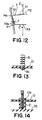
- a portable telephone set of a foldable type according to a second embodiment of this invention is different from that of the first embodiment in a manner of fixing the spring 9 inside the upper housing 2.
- the spring 9 is fixed at its one end to the printed circuit board 10 through the soldered part 9a as illustrated in Fig. 13.
- the spring 9 is fixed in a different manner.
- the printed circuit board 10 is provided with a guide hole 10a.
- a second spring receiving portion 21 is formed on an inner surface of a rear wall 22 opposite to a front wall having the confronting surface and receives the other end of the spring 9.
- the second spring receiving portion 21 extends through the guide hole 10a formed in the printed circuit board 10. In this state, the other end of the spring 9 is received in the second spring receiving portion 21.
- the spring 9 may be replaced by any other elastic member.
- the second spring receiving portion 21 may be called a second elastic member receiving portion.
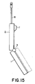
- a portable telephone set of a foldable type is characterized by an arrangement of the earphone unit 7 and the key portion 5.
- the earphone unit 7 is brought into contact at first with an internal area of the key portion 5.
- the contact point between the earphone unit 7 and the lower housing 1 is forced to move towards the hinge portion 3.
- the earphone unit 7 is often caught in the recess between the key pads when the lower and the upper housings 2 are folded. As a consequence, the earphone unit 7 can not slide on the confronting surface of the lower housing 1, so that the folding operation cannot be completed.
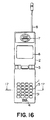
- the portable telephone set of a foldable type according to the third embodiment of this invention has structures of the earphone unit 7 and the key portion 5 as illustrated in Figs. 17 and 18.
- the earphone unit 7 has a semi-elliptical plane formed between a side surface near the hinge portion 3 and the earphone unit top surface 72b.
- the earphone unit top surface 72b is chamfered.
- a plurality of the key pads 51 of the key portion 5 are shown in section taken along a line 17-17 in Fig. 16.
- the key pads 51 are arranged inside, or at a lower level, with respect to the confronting surface of the lower housing 1. It is assumed that each key pad 51 has a width defined between segmented portions of the lower housing 1 in Fig. 17. It is sufficient that the key pads 51 are arranged inside with respect to the confronting surface of the lower housing 1 while the lower and the upper housings 2 are folded.
- a protruding part of the earphone unit 7 is shown.
- the semi-elliptical plane defines a straight line 75 having a length which is selected to be larger than the width of the key pad 51.
- the straight line 75 extends over the entire width of the key pad 51.
Landscapes
- Engineering & Computer Science (AREA)
- Signal Processing (AREA)
- Computer Networks & Wireless Communication (AREA)
- Telephone Set Structure (AREA)
- Transceivers (AREA)
Applications Claiming Priority (3)
| Application Number | Priority Date | Filing Date | Title |
|---|---|---|---|
| JP7071019A JPH08274678A (ja) | 1995-03-29 | 1995-03-29 | 折り畳み可能な携帯無線機 |
| JP71019/95 | 1995-03-29 | ||
| JP7101995 | 1995-03-29 |
Publications (2)
| Publication Number | Publication Date |
|---|---|
| EP0735698A2 true EP0735698A2 (fr) | 1996-10-02 |
| EP0735698A3 EP0735698A3 (fr) | 1999-11-10 |
Family
ID=13448397
Family Applications (1)
| Application Number | Title | Priority Date | Filing Date |
|---|---|---|---|
| EP96105061A Withdrawn EP0735698A3 (fr) | 1995-03-29 | 1996-03-29 | Téléphone portable pliable avec extension de l'écouteur au déploiement du boítier du téléphone |
Country Status (5)
| Country | Link |
|---|---|
| EP (1) | EP0735698A3 (fr) |
| JP (1) | JPH08274678A (fr) |
| KR (1) | KR100194567B1 (fr) |
| AU (1) | AU5041496A (fr) |
| CA (1) | CA2172930A1 (fr) |
Cited By (5)
| Publication number | Priority date | Publication date | Assignee | Title |
|---|---|---|---|---|
| EP0836309A1 (fr) * | 1996-10-11 | 1998-04-15 | Matra Communication | Montage d'un composant électrique dans un appareil |
| GB2335564A (en) * | 1998-03-19 | 1999-09-22 | Samsung Electronics Co Ltd | Folding telephone has earpiece in keypad cover |
| GB2350516A (en) * | 1999-05-26 | 2000-11-29 | Ericsson Telefon Ab L M | Telephone handset with at least two movable elements whose motion is linked or is initiated by pushbutton or incoming call |
| CN112040031A (zh) * | 2019-06-03 | 2020-12-04 | Oppo广东移动通信有限公司 | 设备套装及其折叠式终端设备 |
| DE102020105055A1 (de) | 2020-02-26 | 2021-08-26 | Harman Becker Automotive Systems Gmbh | Elektronisches gerät mit mindestens einem mikrofon |
Families Citing this family (2)
| Publication number | Priority date | Publication date | Assignee | Title |
|---|---|---|---|---|
| KR100606074B1 (ko) * | 1999-11-05 | 2006-07-26 | 삼성전자주식회사 | 폴더 타입 휴대폰의 안테나 접속장치 |
| KR100678190B1 (ko) * | 1999-11-22 | 2007-02-01 | 삼성전자주식회사 | 안테나 장치가 구비된 폴더 |
Family Cites Families (5)
| Publication number | Priority date | Publication date | Assignee | Title |
|---|---|---|---|---|
| JPH04117849A (ja) * | 1990-09-07 | 1992-04-17 | Fujitsu Ltd | カード式電話機 |
| JPH04137323A (ja) * | 1990-09-27 | 1992-05-12 | Mitsubishi Denki Bill Techno Service Kk | 押しボタン装置 |
| JPH0645982A (ja) * | 1992-07-22 | 1994-02-18 | Sony Corp | 携帯型無線電話機 |
| JP2689880B2 (ja) * | 1993-12-28 | 1997-12-10 | 日本電気株式会社 | 携帯電話機 |
| JP2834012B2 (ja) * | 1994-11-08 | 1998-12-09 | 日本電気株式会社 | スピーカ収納型電話機 |
-
1995
- 1995-03-29 JP JP7071019A patent/JPH08274678A/ja active Pending
-
1996
- 1996-03-28 CA CA002172930A patent/CA2172930A1/fr not_active Abandoned
- 1996-03-29 AU AU50414/96A patent/AU5041496A/en not_active Abandoned
- 1996-03-29 KR KR1019960009134A patent/KR100194567B1/ko not_active Expired - Fee Related
- 1996-03-29 EP EP96105061A patent/EP0735698A3/fr not_active Withdrawn
Cited By (7)
| Publication number | Priority date | Publication date | Assignee | Title |
|---|---|---|---|---|
| EP0836309A1 (fr) * | 1996-10-11 | 1998-04-15 | Matra Communication | Montage d'un composant électrique dans un appareil |
| FR2754668A1 (fr) * | 1996-10-11 | 1998-04-17 | Matra Communication | Montage d'un composant electrique dans un appareil |
| GB2335564A (en) * | 1998-03-19 | 1999-09-22 | Samsung Electronics Co Ltd | Folding telephone has earpiece in keypad cover |
| GB2335564B (en) * | 1998-03-19 | 2002-05-29 | Samsung Electronics Co Ltd | Folding communication device |
| GB2350516A (en) * | 1999-05-26 | 2000-11-29 | Ericsson Telefon Ab L M | Telephone handset with at least two movable elements whose motion is linked or is initiated by pushbutton or incoming call |
| CN112040031A (zh) * | 2019-06-03 | 2020-12-04 | Oppo广东移动通信有限公司 | 设备套装及其折叠式终端设备 |
| DE102020105055A1 (de) | 2020-02-26 | 2021-08-26 | Harman Becker Automotive Systems Gmbh | Elektronisches gerät mit mindestens einem mikrofon |
Also Published As
| Publication number | Publication date |
|---|---|
| CA2172930A1 (fr) | 1996-09-30 |
| AU5041496A (en) | 1996-10-10 |
| KR960036394A (ko) | 1996-10-28 |
| JPH08274678A (ja) | 1996-10-18 |
| KR100194567B1 (ko) | 1999-06-15 |
| EP0735698A3 (fr) | 1999-11-10 |
Similar Documents
| Publication | Publication Date | Title |
|---|---|---|
| CA2050849C (fr) | Poste telephonique portatif pliable | |
| US6484016B1 (en) | Device for connecting a main board with an LCD Module in a folder type portable radiotelephone | |
| US6897825B2 (en) | Antenna apparatus for folder type mobile phone | |
| US5243355A (en) | Semiautomatic retractable antenna apparatus | |
| US20080042910A1 (en) | Antenna unit and electrical connection device thereof and portable device having the same | |
| EP1515525A2 (fr) | Assemblage à glissière pour un appareil de communication mobile | |
| GB2330032A (en) | Radio communication device having a retractable keyboard | |
| EP0603012B1 (fr) | Radiotéléphone portable | |
| EP0735698A2 (fr) | Téléphone portable pliable avec extension de l'écouteur au déploiement du boîtier du téléphone | |
| KR100575746B1 (ko) | 폴더형 휴대 단말기 | |
| US20050248492A1 (en) | Antenna device for portable wireless terminal | |
| US6091815A (en) | Flip cover in flip type of portable telephone apparatus | |
| KR20040006977A (ko) | 힌지 모듈을 이용한 슬라이딩 타입 휴대용 무선 단말기 | |
| US20040189537A1 (en) | Movable radio communication apparatus | |
| JP3073116B2 (ja) | 電話機のロック機構 | |
| JP2821638B2 (ja) | 携帯無線機 | |
| KR100724919B1 (ko) | 휴대용 단말기 | |
| KR100585736B1 (ko) | 휴대용 단말기의 힌지장치 | |
| JP3439392B2 (ja) | 携帯無線機 | |
| KR100298355B1 (ko) | 플립형 휴대폰의 힌지 장치 | |
| KR20060004523A (ko) | 음질 개선장치를 구비한 휴대용 단말기 | |
| JP2003294026A (ja) | ヒンジ装置及びヒンジ装置を備えた携帯情報機器 | |
| KR20060068244A (ko) | 푸쉬 푸쉬 방식의 고정 장치를 포함하는 내부 삽입형배터리를 구비한 이동통신 단말기 | |
| KR20050068329A (ko) | 슬라이드형 이동통신단말기 | |
| KR100677486B1 (ko) | 이동통신 단말기 |
Legal Events
| Date | Code | Title | Description |
|---|---|---|---|
| PUAI | Public reference made under article 153(3) epc to a published international application that has entered the european phase |
Free format text: ORIGINAL CODE: 0009012 |
|
| AK | Designated contracting states |
Kind code of ref document: A2 Designated state(s): DE FR GB IT NL SE |
|
| PUAL | Search report despatched |
Free format text: ORIGINAL CODE: 0009013 |
|
| AK | Designated contracting states |
Kind code of ref document: A3 Designated state(s): DE FR GB IT NL SE |
|
| RIC1 | Information provided on ipc code assigned before grant |
Free format text: 6H 04B 1/38 A, 6H 01Q 1/24 B |
|
| 17P | Request for examination filed |
Effective date: 19991004 |
|
| 17Q | First examination report despatched |
Effective date: 20031020 |
|
| STAA | Information on the status of an ep patent application or granted ep patent |
Free format text: STATUS: THE APPLICATION IS DEEMED TO BE WITHDRAWN |
|
| 18D | Application deemed to be withdrawn |
Effective date: 20040302 |