EP0735745A2 - Verfahren und Gerät zur Verarbeitung von visuellen Informationen - Google Patents
Verfahren und Gerät zur Verarbeitung von visuellen Informationen Download PDFInfo
- Publication number
- EP0735745A2 EP0735745A2 EP96302245A EP96302245A EP0735745A2 EP 0735745 A2 EP0735745 A2 EP 0735745A2 EP 96302245 A EP96302245 A EP 96302245A EP 96302245 A EP96302245 A EP 96302245A EP 0735745 A2 EP0735745 A2 EP 0735745A2
- Authority
- EP
- European Patent Office
- Prior art keywords
- image
- visual information
- image data
- signal
- space
- Prior art date
- Legal status (The legal status is an assumption and is not a legal conclusion. Google has not performed a legal analysis and makes no representation as to the accuracy of the status listed.)
- Granted
Links
Images







Classifications
-
- H—ELECTRICITY
- H04—ELECTRIC COMMUNICATION TECHNIQUE
- H04N—PICTORIAL COMMUNICATION, e.g. TELEVISION
- H04N23/00—Cameras or camera modules comprising electronic image sensors; Control thereof
- H04N23/80—Camera processing pipelines; Components thereof
-
- H—ELECTRICITY
- H04—ELECTRIC COMMUNICATION TECHNIQUE
- H04N—PICTORIAL COMMUNICATION, e.g. TELEVISION
- H04N23/00—Cameras or camera modules comprising electronic image sensors; Control thereof
- H04N23/95—Computational photography systems, e.g. light-field imaging systems
- H04N23/951—Computational photography systems, e.g. light-field imaging systems by using two or more images to influence resolution, frame rate or aspect ratio
Definitions
- This invention relates to a visual information processing method and apparatus, particularly a visual information processing method and apparatus capable of extracting feature quantities from a two-dimensional image signal and of encoding the signal.
- a conventional image input unit uses an input system in which a coordinate transformation from a coordinate system in real space to coordinates on a sensor plane is linear.
- a coordinate transformation from a coordinate system in real space to coordinates on a sensor plane is linear.
- there is the usual lens system employed in a video camera namely a lens system which realizes an identity mapping, and a line sensor used in a scanner. If the spacing between the sensors of an array sensor is constant in such an input system, sampling data having the same resolution are obtained over the entire area covered by the array sensor. Accordingly, if the sampling frequency is high enough, an advantage is that the input data will contain enough information for processing to be executed continuously.
- a system is available in which use is made of a wide-angle lens in order to a view a wide area at one time.
- This system implements a monotonous scale conversion of the type in which the image becomes smaller in size as distance from the optical axis of the lenses increases.
- the advantage of this system is that it is possible to view all of a hemisphere at one time.
- An ordinary lens system equipped with an optic-axis control device and a wide-angle lens for viewing the entirety of a hemisphere at one time are used in combination as the visual-information input unit of a monitoring apparatus, self-propelled vehicle or self-controller robot, which require that visual information over a wide range be obtained at one time.
- the direction of the optic axis of the ordinary lens system is decided based upon coarse information of the surroundings obtained by the wide-angle lens.
- a panoramic input unit realized by rotating the array sensor also has been proposed in order to obtain high-resolution visual information covering a wide range.
- the system provides full-peripheral high-resolution data if a suitable amount of time is expended.
- a concern of the present invention is to provide a visual information processing method and apparatus for obtaining an appropriate amount of visual information at high speed.
- Another concern of the present invention is to provide a visual information processing method and apparatus whereby a multi-resolution approximation or multi-resolution space, which is effective as an expedient for expressing an image, is obtained through a simple arrangement.
- the present invention provides a visual information processing method in a visual information processing apparatus for acquiring and processing visual information, characterized by successively changing visual information with regard to a desired spatial position, reading image data at each image-forming position and storing the image data in correspondence with the spatial position.
- the visual information is successively changed by changing the image-forming position corresponding to the spatial position by moving of the optic axis of a lens.
- the lens is a wide-angle lens.
- the visual information is successively altered by zooming.
- the visual information is successively changed by filtering which relies upon a two-dimensional filter.
- there are at least two spatial positions image data at each image-forming position are read out in correspondence with each spatial position, and the image data are stored in correspondence with each spatial position.
- the method is further characterized by a step of detecting at least two above-mentioned spatial positions.
- the method is further characterized by a step of changing the read image data to image data of multi-resolution space corresponding to the spatial positions, or to a power spectrum.
- the invention further provides a visual information processing apparatus for acquiring and processing visual information, characterized by comprising visual information changing means for changing obtained visual information with respect to a desired spatial position, and visual information memory means for reading image data at each image-forming position and storing the image data in correspondence with the spatial position.
- the visual information changing means has optic-axis moving means for moving the optic axis of a lens.
- the lens is a wide-angle lens.
- the visual information changing means has means for controlling zooming.
- the visual information changing means has means for performing predetermined two-dimensional filtering.
- there are two or more spatial positions and the visual information changing means reads the changing image data in correspondence with each spatial position and stores the image data in correspondence with each spatial position.
- the method is further characterized by a step of detecting the plurality of spatial positions.
- the apparatus is further characterized by having position detecting means for detecting the plurality of spatial positions.
- the apparatus is further characterized by having visual information processing means for changing the read image data to image data of multi-resolution space corresponding to the spatial positions, or to a power spectrum.
- a visual information processing apparatus is characterized by comprising image input means which includes a wide-angle lens, autofocus means, rangefinding means and an array sensor, input-parameter control means for controlling an input parameter of the image input means, external memory means for storing image information that enters from the image input means, and calculating means which, on the basis of distance to an object obtained from the rangefinding means and a coordinate transformation equation of the wide-angle lens, calculates an input-parameter control quantity, which controls the input parameter, and timing at which the image information is recorded in external recording means.
- the apparatus is further characterized by comprising two-dimensional filter means for subjecting an output image from the array sensor to more than one stage of filtering.
- the apparatus is further characterized by comprising extremum detecting means for detecting an extremum of a two-dimensional signal outputted by the array sensor or two-dimensional filter means, and extremum memory means for storing coordinates of the detected extremum.
- Fig. 1 is a block diagram illustrating an example of the construction of a visual information processing apparatus according to a first embodiment of the present invention. The elements constituting this apparatus will now be described.
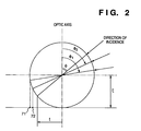
- a coordinate transformation performed by the wide-angle lens 10a is shown in Fig. 2.
- An array sensor 10b which is a two-dimensional sensor comprising sensors arrayed in the form of a two-dimensional lattice, converts continuous spatial coordinates to discrete one.
- the output of a sensor whose index is m in the horizontal direction and n in the vertical direction is represented by g m,n .
- a rangefinding mechanism 10c measures range to an object of interest, and an autofocus mechanism 10d achieves focusing at the range measured. These mechanisms are well known in camera technology.
- a two-dimensional filter 11 subjects the output signal of the array sensor 10b, namely the discrete two-dimensional image ⁇ g m,n ⁇ m,n , to the following digital filtering:
- a filter configuration having a low-pass (LP) characteristic is selected.
- LP low-pass
- a ⁇ 2 G operator is used.
- a discrete Gabor filter having a detection center frequency ⁇ p and a spatial constant ⁇ is applied.
- a jth filter output (counting from the optic axis) is as follows:
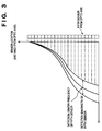
- Fig. 3 illustrates a frequency characteristic resulting from the wide-angle lens 10a and two-dimensional filter 11.
- the lens 10a and filter 11 will also be referred to as a "wide-angle lens input system" below.
- Distance from the optic axis of each sensor constituting the array sensor 10b is plotted along the vertical axis, and the (local) spatial frequency band sensed by each sensor is plotted along the horizontal axis.
- the center frequency sensed by the wide-angle lens input system decreases monotonously with displacement from the optic axis.
- this wide-angle lens input system senses components, which are less than the maximum frequency capable of being sensed by the system, in appropriate bandwidths.
- Fig. 3 illustrates the frequency band detected by the fifth sensor counting from the sensor situated on the optic axis. It will be appreciated that the frequency band detected by the 11th sensor is approximately half that detected by the fifth sensor.
- An input-parameter controller 13 calculates the amount of movement of the wide-angle lens 10a, namely the angle in the vertical direction and the angle in the horizontal direction, and controls the movement of the optic axis (inclusive of rotational movement and translation) based upon a timing signal sent from a recording controller 12, described later.
- the direction ( ⁇ 1 , ⁇ 1 ) of an object of interest can be calculated from the center position of a sensor 71 which is currently forming the image of the object. Considering a line between the center position of the sensor 71 and the center position 70 corresponding to the optic axis sensor 72 selected on the basis of this line, which is desired to be the one that forms the image of the object of interest at the next instant in time.
- the direction ( ⁇ 2 , ⁇ 2 ) of the object at the next instant in time is calculated from the center position of the sensor 72, and the amount of rotation of the optic axis to shift ( ⁇ 1 , ⁇ 1 ) to ( ⁇ 2 , ⁇ 2 ) is calculated.
- the detection frequency band of a sensor is shifted more and more toward the lower side of frequency the farther the sensor is from the center position 70 of the optic axis. Accordingly, by virtue of the control method described above, a power spectrum of the image data of the object of interest is successively obtained, in the form of time-series data from the low-frequency components, as the output of sensors forming the image of the object.
- Fig. 7 illustrates the plane of the array sensor 10b.
- the center position 70 of the optic axis corresponds to a sensor which forms the image of the object situated on the optic axis of the optical system in a space being observed. If the object of interest is having its image formed at the position of sensor 71 on the plane of the array sensor 10b, then the sensed frequency component is that of the lowest frequency band since sensor 71 is most distant from the center position 70 of the optic axis.
- the sensor 71 forming the image of the object of interest and the center position 70 of the optic axis are connected by a line segment, and the optic axis is moved in such a manner that the image of the object of interest will be formed on the sensor 72, which is on this line segment and one closer to the center position 70 of the optic axis. Since the sensor 72 is closer to the center position 70 of the optic axis than the initial sensor 71, the frequency component sensed by the sensor 72 is in a frequency band slightly higher than that of the component sensed by the initial sensor 71. When the image of the object of interest has been formed at the center position 70 of the optic axis, the highest frequency is sensed by the corresponding sensor. Thus, by shifting the position at which the image of the object is formed incrementally closer to the center position 70 of the optic axis on the plane of the array sensor 10b, intensities from low to high frequency bands are obtained in a time series.
- the memory controller 12 controls write timing in such a manner that the timing at which the output image signal from the two-dimensional filter 11 is written in an external memory 14 and the timing at which the optic axis of the wide-angle lens 10 is moved will not coincide.
- the external memory 14 stores the output image signal from the two-dimensional filter 11 based upon a signal from the memory controller 12. It should be noted that the external memory 14 may store the output image signal of the two-dimensional filter 11, which signal conforms to the movement of the optic axis, as is, or may store the signal upon putting it in the format of a power spectrum or the like by a controller 15, described below.
- the CPU 15a controls the overall apparatus, particularly a key input unit 15c, a display unit 15b, the memory controller 12 and the external memory 14.
- the CPU 15a has a storage medium such as a ROM for storing a control procedure and a RAM for temporarily storing data.
- a program for putting the output image signal in the format of a multi-resolution expansion or power spectrum before or after storage in the external memory 14 also is provided. It should be noted that this program may be loaded in the RAM from an external storage medium such as a floppy disk or downloaded from a host computer or via a communication line.
- the display unit 15b is used to confirm an input from the key input unit 15c, confirm the status of the apparatus or display the results of processing a multi-resolution expansion or power spectrum.
- This unit is for entering a command or data from an external device.
- the key input unit 15c is utilized to enter coordinate values of the location at which an object of interest is situated.
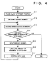
- FIG. 4 is a flowchart showing the procedure of the operation. The description will be limited to rotation of the optic axis in order to avoid a complex operation.
- Step S11 The object is placed at a preset position and the position coordinates ( ⁇ 1 , ⁇ 1 ) of the object relative to the wide-angle lens system are entered from a key input unit 15c.
- Step S12 The position at which the image of the object is formed and the index of the sensor corresponding to this position are calculated based upon the coordinate transformation equation [Equation (1)] cited above. It should be noted that the preset position desirably is adjusted in such a manner that the image is formed on the sensor situated at the boundary portion of the array sensor 10b.
- Step S13 The output of the above-mentioned sensor is recorded in the external memory 14.
- Step S14 When the position at which the image is formed arrives at the sensor located at the center position of the optic axis, processing is terminated.
- Step S15 The center position, on the plane of the sensor array, of a sensor closer by one sensor to the center position of the optic axis than the above-mentioned sensor is calculated.
- Step S16 On the basis of the coordinate transformation equation [Equation (1)], the direction ( ⁇ 2 , ⁇ 2 ) of a light ray whose image is formed on the center position of the sensor closer by one sensor to the center position of the optic axis is calculated, and the amount of rotational movement ( ⁇ 2 - ⁇ 1 , ⁇ 2 - ⁇ 1 ) is calculated,
- Step S17 The optic axis is rotated based upon the amount of rotational movement, after which the program returns to step S13.
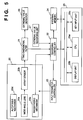
- Fig. 5 is a block diagram illustrating an example of the construction of a visual information processing apparatus according to a second embodiment of the present invention.
- the encoding of an input image is performed by detecting a feature point and acquiring a feature quantity in the neighborhood of the feature point.
- the apparatus shown in Fig. 5 differs from that of Fig. 1 in the provision of an extremum detector 26 and a extremum memory 27.
- the other elements function in the same manner as those shown in Fig. 1.
- the extremum detector 26 detects an extremum (maximum value, minimum value or absolute value of either of these) from the output of the two-dimensional filter 21 and outputs the pole value upon correlating it with the coordinates thereof.
- the detection of the extremum may be performed by detecting a reversal in the increase/decrease of the two-dimensional filter 21. It is particularly preferred that noise be removed by performing detection in combination with a predetermined threshold value.
- the extrema outputted by the extremum detector 26 and the coordinates thereof on the array sensor are stored in the extremum memory 27.
- Step S21 The extrema and the coordinate values thereof are acquired from the two-dimensional filter 21 and stored in the extremum memory 27.
- Step S22 The frequency components obtained at the present point in time at the positions at which the extrema are present are confirmed, and the coordinates values and intensities are stored in the external memory 24.
- Step S23 One extremum is selected on the basis of a suitable criterion for the coordinate values of the extremum that have been stored in the extremum memory 27.
- a suitable criterion is chosen, such as a maximum value, minimum value or predetermined range.
- Step S24 The center position of the optic axis on the array sensor 20b and the position of the above-mentioned extremum are connected by a line segment, an amount of control for movement of the optic axis is calculated so as to move the optic axis in the direction of a sensor situated on the line segment, and the optical axis is rotated (see Fig. 7).
- Step S25 After movement, the position of each extremum and the frequency component obtained in the neighborhood thereof are stored in the external memory 24 in a form correlated with the coordinate values.
- Step S26 It is determined whether the center position of the optic axis has come into agreement with the position of the above-mentioned extremum. If the answer is "YES”, the next extremum is selected. If the answer is "NO”, processing for moving the optic axis in such a manner that the extremum will approach the center position of the optic axis is repeated.
- Step S27 If the series of processing steps for bringing the center position of the optic axis into coincidence with all extremum is finished, encoding is terminated.
- movement of the optic axis includes translation and zooming. Furthermore, if this embodiment is implemented at a predetermined period or at the timing of the appearance of feature points or movement thereof, it is possible to detect the feature points moved and to acquire the feature quantities in the vicinity thereof.
- the foregoing embodiments provide a visual information processing method and apparatus for obtaining suitable visual information at high speed.
- the embodiments further provide a visual information processing method and apparatus which, through a simple arrangement, make it possible to obtain a multi-resolution approximation or multi-resolution space effective as an expedient for expressing an image. More specifically, the advantages of the embodiments are as follows:
- This embodiment has been devised to improve the efficiency with which an image is accepted in the image sensing system of a scanner or the like employing a fisheye lens in the image sensing system.
- the efficiency is improved by suitably controlling a two-dimensional image input unit, a device for extracting a feature quantity of a two-dimensional image, an encoder, etc.
- a conventional image input unit may use an input system which is an ordinary lens system such as in a video camera, a lens system for realizing identity mapping or a line sensor such as in a scanner, or an input system in which the coordinate transformation from a coordinate system in real space to coordinates on a sensor plane is linear.
- an input system which is an ordinary lens system such as in a video camera, a lens system for realizing identity mapping or a line sensor such as in a scanner, or an input system in which the coordinate transformation from a coordinate system in real space to coordinates on a sensor plane is linear.
- the above-mentioned input system samples any subregion of a given image at fixed and uniform sampling period, even if a subregion includes no utilizable information. Consequently, the amount of information obtained with regard to such data is small for the time expended.
- the present invention has been devised to solve this problem. Specifically, an area in which there is no change in an image signal is subjected to coarse sampling and an area where there is a great change in the image signal is subjected to fine sampling. As a result, image input which is efficient in terms of time is realized.
- numeral 101 denotes a fisheye lens serving as the image-input optical system.
- a stereographic projection lens is described as the fisheye lens, another fisheye lens, such as an orthogonal projection lens or equisolidangle lens can be used.
- ⁇ represent the radius of polar coordinates on an image plane located at a position which is a distance L from the lens center
- ⁇ represent the radius of polar coordinates after the image is transformed by the fisheye lens
- ⁇ represent the azimuth angle
- ⁇ the angle of incidence of light with respect to the optic axis
- ⁇ focal length of the lens.
- ⁇ Ltan( ⁇ ) From these it is possible to express ⁇ as a function of ⁇ in the equation below.
- FISHEYE -1 ( ⁇ ) L( ⁇ / ⁇ )/ ⁇ 1-( ⁇ /2 ⁇ ) 2 ⁇ This means a coordinate transformation from a ( ⁇ , ⁇ ) coordinate system to a ( ⁇ , ⁇ ) coordinate system in a stereographic projection lens.
- Numeral 112 denotes an array sensor for image sensing.
- a two-dimensional image sensor in which sensors are arrayed in a two-dimensional lattice.
- a buffer 102 stores output data from the array sensor 112
- a buffer 103 stores image data from an image data correction unit 117
- a buffer 104 stores image data from an image data restoration unit 118
- a buffer 105 stores optic-axis position data which correspond to the image data stored in the buffer 102.
- Numerals 106, 107, 108, 109, 110, 111 denote status bits for performing various operations and controlling state in the image input unit according to this embodiment.
- the bits store the values of "0" and "1".
- the array sensor 112 converts the optical image formed by the fisheye lens 101 to a digital image in which spatial coordinates are represented as discrete values, and outputs the digital image.
- the array sensors 112 executes a procedure for storing the data in the buffer 102 only when the status bit 106 is "1" and, moreover, the status bits 107, 108 are "0".
- the procedure for storing data in the buffer 102 is completed by setting the status bit 106 to "0" and the status bits 107, 108 to "1".
- Numeral 113 denotes the case of the image input unit, in which the fisheye lens 101 and array sensor are secured.
- An initializing unit 114 initializes the image input unit, and an input/output port 115 receives input parameters from the outside and sends image data to the outside.
- An optic-axis position controller 116 (which corresponds to the input-parameter controller of Fig. 1) starts a procedure for controlling the optic axis when the status bit 109 is "1" and is independent of the values of the status bits 106, 107 and 108.
- the amount of movement of the optic axis of the fisheye lens 101 is calculated and the case 113 is moved two-dimensionally. A method of calculating the amount of movement of the optic axis will now be described.
- the coordinates calculated give the two-dimensional amount of movement of the optic axis.
- the optic-axis position controller 116 moves the case 113 in such a manner that the optic axis will coincide with the coordinates (x 1 ,y 1 ).
- the procedure for controlling the optic axis is completed by setting the status bit 109 to "0" and the status bit 106 to "1".
- the image data correction unit 117 starts a procedure for correcting the image data when the status bit 106 is "0" and the status bit 107 is "1". This procedure corrects image data located in a predetermined range measured from the optic axis. An example of the procedure will be described for a case where the index of the sensor corresponding to the optic axis is (Mc,Nc) and a range to be corrected is specified by the radius from the optic axis R.
- the correcting procedure is completed by setting the status bit to "0".
- the image data restoration unit 118 executes a procedure only when the status bit 107 is "0" and the status bit 108 is "1".
- the procedure executed by the image data restoration unit 118 reproduces a single two-dimensional image based upon the image data that have been stored in the buffer 103 and the coordinates of the optic axis that have been stored in the buffer 105.
- the image input unit constructed as set forth above enters a given target image in the following manner:
- any procedure described above is determined by the value of the status bits. This means that the optic-axis position controller 116 is allowed to execute the procedure except when the array sensor 112 is operating. In other words, the optic-axis position controller 116 is allowed to execute the procedure at the same time as either the image data correction unit 117 or image data restoration unit 118.
- the initializing unit 114 sets the status bits 106 ⁇ 108, 110 to "0" and sets the status bits 109, 111 to "1".
- the array sensor 112 outputs a detection signal to the buffer 102 only when the status bit 106 is "1", the status bit 107 is “0” and the status bit 108 is “0", and sets the status bit 106 to "0", rewrites the status bits 107 ⁇ 109 to "1" and writes the present coordinates of the optic axis in the buffer 105 if one frame of the image has been outputted.
- the image data correction unit 117 corrects the image data recorded in the buffer 102 by a prescribed correction method only when the status bit 106 is "0” and the status bit 107 is "1”, outputs the corrected image data to the buffer 103 and rewrites the status bit 107 to "0" when recording is finished.
- the image data restoration unit 118 combines an image, which is obtained by converting the image data recorded in the buffer 103 on the basis of the coordinates of the optic axis recorded in the buffer 105, with the image data recorded in the buffer 104 only when the status bit 107 is "0" and the status bit 108 is “1", and rewrites the status bit 108 to "0" when the procedure is completed.
- the optic-axis position controller 116 moves the case 113 to the predetermined home position when the status bits 109 and 111 are "1” and rewrites the status bit 109 to "0” and the status bit 106 to "1" when the movement is completed.
- the optic-axis position controller 116 reads in the data recorded in the buffer 102 only when the status bit 109 is "1" and the status bit 111 is "0", selects one pixel in the image data by a predetermined processing method, calculates the coordinates corresponding to this pixel on the input object of interest from the index of the selected pixel, rewrites the status bit 110 to "1" when the calculated coordinate values are greater than predetermined values, moves the case 113 in two dimensions based upon the calculated coordinates when the values thereof are not greater than the predetermined values, and rewrites the status bit 109 to "0" and the status bit 106 to "1" when movement is completed.
- the input/output unit 115 outputs the image data recorded in the buffer 104 only when the status bit 110 is "1".
- an image sensed by the fisheye lens 101 is converted to an electric signal by the array sensor 112.
- the image is not sampled uniformly in the same way throughout. Rather, feature points of the image are sensed and a change in feature points is detected.
- the portion of an image which changes is identified and the image can be sampled while moving the image sensing system. This makes it possible to discriminate an unchanging background portion of an image from the principal part of the image desired to be sensed and to performing image sensing very efficiently.
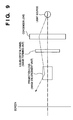
- FIG. 9 black-and-white
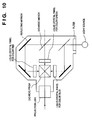
- Fig. 10 color
- the monochromatic system is provided for each of the colors R, G and B.
- an image is displayed by a liquid-crystal display panel, light emitted by a light source is condensed by a condenser lens, and the displayed image is illuminated by the condensed light.
- the image is enlarged and projected upon a screen by a projection lens. This is referred to as so-called "liquid-crystal projection”.
- Fig. 10 illustrates a system which, in principle, is similar to the monochromatic system of Fig. 9.
- This system has an image-forming liquid-crystal panel for each of the color components R, G, B.
- light from a light source is acted upon by a filter, at least three reflective mirrors and at least two dichroic mirrors, the resulting light rays are combined and the light is then projected upon a screen via a projection lens.
- the effective picture is limited to an area in which the coordinate system is not distorted. It is also so arranged that resolution will be uniform over the entire image.
- the following two methods are available as methods of widening the angle of view in order to obtain presence with such an arrangement: The first entails increasing the number of pixels of the image in order to maintain the resolution of the image, and the second entails sacrificing resolution in an effort to maintain the pixel size of the image.
- a fisheye lens is used as an optical lens system for sensing a scene of interest, thereby making it possible to achieve a wide angle of view of over 180° ⁇ with a high resolution near the optic axis and a lower resolution at the periphery.
- a limited area desired to be recorded accurately and a wide area peripheral to the limited area can be recorded at the same time.
- a processing system for implementing an inverse mapping of the fisheye lens is provided as a display unit, thereby making it possible to view an image, which has been distorted by the fisheye lens, as an undistorted image having a viewing angle of more than 180° ⁇ .
- FIG. 11 is a diagram best showing an image display unit according to this embodiment.
- An optical lens system 201 includes a fisheye lens.
- the radius r 1 of a polar coordinate system after transformation by the fisheye lens is written as follows using the angle of incidence ⁇ 1 with respect to the optic axis:
- ⁇ represents the focal length of the lens.
- a filter system 202 is inserted into the optical system.
- the incident light is decomposed into the R, G, B components by the filter system.
- a two-dimensional array sensor 203 which may be an image sensing device such as a CCD, samples the image from the fisheye lens two-dimensionally. Use is made of an ordinary array sensor having a uniform sensor spacing.
- a case 204 housing the image sensing system is used to fix the optical lens system 201, the filter system 202 and the two-dimensional array sensor 203.
- a signal recording unit 205 records the output signal of the two-dimensional array sensor 203 on a signal recording medium 206.
- the latter may be a semiconductor memory, a magnetic recording medium or an optical recording medium.
- a signal reproducing unit 207 read out the signal that has been recorded on the signal recording medium.
- a backlighting light source 208 produces collimated light for illuminating a display that displays the image reproduced by the image reproducing unit 207.
- a liquid-crystal panel 209 displays the image reproduced by the image reproducing unit 207. More specifically, the liquid-crystal panel 209 is capable of controlling the transmittance of each pixel based upon the two-dimensional signal read out by the image reproducing unit 207. An image is produced as a result.
- a back-projection-type screen 210 is observed by the viewer.
- a case 211 secures the collimated-light source 208, the liquid-crystal panel 209 and the screen 210 in the positional relationship illustrated, thereby constructing the image display unit.
- video over a viewing angle of 180° ⁇ can be obtained from an image represented by a limited two-dimensional planar area, namely the liquid-crystal panel 209.
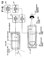
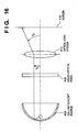
- Fig. 13 is a diagram illustrating another embodiment, which provides an optical lens system with the screen-image conversion function of the display system according to the fourth embodiment.
- An optical lens system 301 includes a fisheye lens the same as that of the fourth embodiment.
- Numeral 302 denotes a filter system, 303 a two-dimensional array sensor, 304 a case, 305 a signal recording unit, 306 a signal recording medium, 307 a signal reproducing unit, 308 a collimated-light source and 309 a liquid-crystal panel, which are identical with those of the fourth embodiment.
- numeral 310 denotes an optical lens system of the image display section, and 311 represents a case for fixing the collimated light source 308, liquid-crystal panel 309 and optical lens system 310 in the positional relationship illustrated.
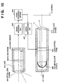
- Fig. 15 is a diagram illustrating another embodiment.
- the display system is of the projector type, in which an image is projected on a screen.
- Numeral 401 denotes an optical lens system
- 402 a filter system
- 403 a two-dimensional array sensor
- 404 a case
- 405 a signal recording unit
- 406 a signal recording medium
- 407 a signal reproducing unit
- 408 a collimated-light source
- 409 a liquid-crystal panel, which are identical with those of the fourth embodiment.
- numeral 410 denotes an optical lens system
- 411 represents a case for fixing the collimated-light source 408, liquid-crystal panel 409 and optical lens system 410 in the positional relationship illustrated.
- Numeral 412 denotes a front-projection-type screen.
- video over a viewing angle of 180° ⁇ can be obtained from an image represented by a limited two-dimensional planar area, namely the liquid-crystal panel 309.
- Fig. 17 is a diagram illustrating another embodiment. According to this embodiment, high-resolution portions over a wide viewing angle can be changed by making it possible to rotate both the image sensing unit and the display unit about two axes.
- Numeral 501 denotes an optical lens system, 502 a filter system, 503 a two-dimensional array sensor and 504 a case, which are identical with those of the fourth embodiment.
- Numeral 505 denotes a two-axis rotation device which makes it possible to rotate the case 504 about two axes, i.e., to perform image sensing over any viewing angle.
- Numeral 506 denotes a rotational-angle detector for detecting the angle of rotation of the case 504.
- Numeral 507 denotes a signal recording unit, 508 a signal recording medium, 509 a signal reproducing unit, 510 a collimated-light source and 511 a liquid-crystal panel, which are identical with those of the fourth embodiment.
- Numeral 512 denotes an optical lens system and 513 a case, which are identical with those of the sixth embodiment.
- Numeral 514 denotes a two-axis rotation device which makes it possible to rotate the case 514 about two axes.
- Numeral 515 denotes a rotation controller for controlling the angle of rotation of the case 513.
- Numeral 516 denotes a screen the same as that of the sixth embodiment.
- Numeral 517 denotes a signal processing unit for controlling the display unit based upon a signal from the signal reproducing unit 509.
- the display side will be described next.
- an area displayed at a high resolution can be changed dynamically.
- the present invention can be applied to a system constituted by a plurality of devices (e.g., host computer, interface, reader, printer) or to an apparatus comprising a single device (e.g., copy machine, facsimile).
- devices e.g., host computer, interface, reader, printer
- apparatus comprising a single device (e.g., copy machine, facsimile).
- an embodiment of the present invention can include providing a storage medium storing program codes for performing the aforesaid processes to a system or an apparatus, reading the program codes with a computer (e.g., CPU, MPU) of the system or apparatus from the storage medium, then executing the program.
- a computer e.g., CPU, MPU
- the program codes read from the storage medium realize the functions according to the embodiments, and the storage medium storing the program codes constitutes the invention.
- the storage medium such as a floppy disk, a hard disk, an optical disk, a magneto-optical disk, CD-ROM, CD-R, a magnetic tape, a non-volatile type memory card, and ROM can be used for providing the program codes.
- the present invention includes a case where an OS (operating system) or the like working on the computer performs a part or entire processes in accordance with designations of the program codes and realizes functions according to the above embodiments.
- the present invention also includes a case where, after the program codes read from the storage medium are written in a function expansion card which is inserted into the computer or in a memory provided in a function expansion unit which is connected to the computer, CPU or the like contained in the function expansion card or unit performs a part or entire process in accordance with designations of the program codes and realizes functions of the above embodiments.
Landscapes
- Engineering & Computer Science (AREA)
- Multimedia (AREA)
- Signal Processing (AREA)
- Computing Systems (AREA)
- Theoretical Computer Science (AREA)
- Image Processing (AREA)
- Studio Devices (AREA)
- Image Input (AREA)
Applications Claiming Priority (6)
| Application Number | Priority Date | Filing Date | Title |
|---|---|---|---|
| JP7651495A JPH08272939A (ja) | 1995-03-31 | 1995-03-31 | 視覚情報処理方法及びその装置 |
| JP76514/95 | 1995-03-31 | ||
| JP7651495 | 1995-03-31 | ||
| JP7001196 | 1996-03-26 | ||
| JP8070011A JPH09261523A (ja) | 1996-03-26 | 1996-03-26 | 画像入力装置及び画像記録再生装置 |
| JP70011/96 | 1996-03-26 |
Publications (3)
| Publication Number | Publication Date |
|---|---|
| EP0735745A2 true EP0735745A2 (de) | 1996-10-02 |
| EP0735745A3 EP0735745A3 (de) | 1997-12-10 |
| EP0735745B1 EP0735745B1 (de) | 2004-10-13 |
Family
ID=26411186
Family Applications (1)
| Application Number | Title | Priority Date | Filing Date |
|---|---|---|---|
| EP96302245A Expired - Lifetime EP0735745B1 (de) | 1995-03-31 | 1996-03-29 | Verfahren und Gerät zur Verarbeitung von visuellen Informationen |
Country Status (4)
| Country | Link |
|---|---|
| US (1) | US6493031B1 (de) |
| EP (1) | EP0735745B1 (de) |
| CA (1) | CA2173091C (de) |
| DE (1) | DE69633589T2 (de) |
Families Citing this family (17)
| Publication number | Priority date | Publication date | Assignee | Title |
|---|---|---|---|---|
| US6786420B1 (en) | 1997-07-15 | 2004-09-07 | Silverbrook Research Pty. Ltd. | Data distribution mechanism in the form of ink dots on cards |
| JPH10334212A (ja) * | 1997-04-01 | 1998-12-18 | Fuji Photo Film Co Ltd | 付加情報付き画像ファイルからの画像プリントシステム |
| US6618117B2 (en) | 1997-07-12 | 2003-09-09 | Silverbrook Research Pty Ltd | Image sensing apparatus including a microcontroller |
| US7110024B1 (en) | 1997-07-15 | 2006-09-19 | Silverbrook Research Pty Ltd | Digital camera system having motion deblurring means |
| AUPO850597A0 (en) | 1997-08-11 | 1997-09-04 | Silverbrook Research Pty Ltd | Image processing method and apparatus (art01a) |
| US6690419B1 (en) | 1997-07-15 | 2004-02-10 | Silverbrook Research Pty Ltd | Utilising eye detection methods for image processing in a digital image camera |
| US6624848B1 (en) | 1997-07-15 | 2003-09-23 | Silverbrook Research Pty Ltd | Cascading image modification using multiple digital cameras incorporating image processing |
| US6879341B1 (en) | 1997-07-15 | 2005-04-12 | Silverbrook Research Pty Ltd | Digital camera system containing a VLIW vector processor |
| US6985207B2 (en) | 1997-07-15 | 2006-01-10 | Silverbrook Research Pty Ltd | Photographic prints having magnetically recordable media |
| US20040119829A1 (en) | 1997-07-15 | 2004-06-24 | Silverbrook Research Pty Ltd | Printhead assembly for a print on demand digital camera system |
| AUPO802797A0 (en) | 1997-07-15 | 1997-08-07 | Silverbrook Research Pty Ltd | Image processing method and apparatus (ART54) |
| AUPP702098A0 (en) | 1998-11-09 | 1998-12-03 | Silverbrook Research Pty Ltd | Image creation method and apparatus (ART73) |
| AUPQ056099A0 (en) | 1999-05-25 | 1999-06-17 | Silverbrook Research Pty Ltd | A method and apparatus (pprint01) |
| JP4154820B2 (ja) * | 1999-12-09 | 2008-09-24 | 三菱電機株式会社 | 画像表示装置のドットクロック調整方法およびドットクロック調整装置 |
| KR101161803B1 (ko) * | 2005-05-25 | 2012-07-03 | 삼성전자주식회사 | 가버 필터 및 그것의 필터링 방법, 그리고 그것을 이용한영상 처리 방법 |
| EP1964451B1 (de) | 2005-12-15 | 2011-07-06 | Koninklijke Philips Electronics N.V. | System und verfahren zur herstellung einer künstlichen atmosphäre |
| US8417062B2 (en) * | 2009-10-19 | 2013-04-09 | Ut-Battelle, Llc | System and method for stabilization of fisheye video imagery |
Family Cites Families (16)
| Publication number | Priority date | Publication date | Assignee | Title |
|---|---|---|---|---|
| US4227212A (en) * | 1978-09-21 | 1980-10-07 | Westinghouse Electric Corp. | Adaptive updating processor for use in an area correlation video tracker |
| JPS5654479A (en) * | 1979-10-12 | 1981-05-14 | Hitachi Ltd | Picture image data processor |
| US5031049A (en) * | 1984-05-25 | 1991-07-09 | Canon Kabushiki Kaisha | Automatic object image follow-up device |
| JPH0810909B2 (ja) * | 1987-05-07 | 1996-01-31 | 松下電器産業株式会社 | ビデオカメラ |
| JPH0220959A (ja) * | 1987-12-28 | 1990-01-24 | Minolta Camera Co Ltd | 画像データ入出力制御装置 |
| US5012270A (en) | 1988-03-10 | 1991-04-30 | Canon Kabushiki Kaisha | Image shake detecting device |
| JP2953712B2 (ja) * | 1989-09-27 | 1999-09-27 | 株式会社東芝 | 移動物体検知装置 |
| JP2677312B2 (ja) * | 1991-03-11 | 1997-11-17 | 工業技術院長 | カメラワーク検出方法 |
| US5185667A (en) | 1991-05-13 | 1993-02-09 | Telerobotics International, Inc. | Omniview motionless camera orientation system |
| US5990941A (en) * | 1991-05-13 | 1999-11-23 | Interactive Pictures Corporation | Method and apparatus for the interactive display of any portion of a spherical image |
| US5581309A (en) * | 1992-02-03 | 1996-12-03 | Sanyo Electric Co., Ltd. | Motion vector detecting circuit |
| KR100276681B1 (ko) * | 1992-11-07 | 2001-01-15 | 이데이 노부유끼 | 비디오 카메라 시스템 |
| US5539491A (en) * | 1993-06-15 | 1996-07-23 | Kyocera Corporation | Back-driven type autofocus camera |
| JP3431953B2 (ja) | 1993-07-27 | 2003-07-28 | キヤノン株式会社 | カメラ制御装置及び方法 |
| US5508734A (en) * | 1994-07-27 | 1996-04-16 | International Business Machines Corporation | Method and apparatus for hemispheric imaging which emphasizes peripheral content |
| US5682197A (en) * | 1995-05-12 | 1997-10-28 | Eastman Kodak Company | Electronic panoramic camera for use with an external processor |
-
1996
- 1996-03-28 US US08/623,224 patent/US6493031B1/en not_active Expired - Fee Related
- 1996-03-29 EP EP96302245A patent/EP0735745B1/de not_active Expired - Lifetime
- 1996-03-29 CA CA002173091A patent/CA2173091C/en not_active Expired - Fee Related
- 1996-03-29 DE DE69633589T patent/DE69633589T2/de not_active Expired - Lifetime
Also Published As
| Publication number | Publication date |
|---|---|
| EP0735745B1 (de) | 2004-10-13 |
| US6493031B1 (en) | 2002-12-10 |
| CA2173091A1 (en) | 1996-10-01 |
| DE69633589T2 (de) | 2005-10-20 |
| EP0735745A3 (de) | 1997-12-10 |
| DE69633589D1 (de) | 2004-11-18 |
| CA2173091C (en) | 2000-06-13 |
Similar Documents
| Publication | Publication Date | Title |
|---|---|---|
| US6493031B1 (en) | Visual information processing method and apparatus for extracting feature quantities from a two-dimensional image signal | |
| US6393162B1 (en) | Image synthesizing apparatus | |
| US6389179B1 (en) | Image combining apparatus using a combining algorithm selected based on an image sensing condition corresponding to each stored image | |
| US7893971B2 (en) | Light source estimation device that captures light source images when it is determined that the imaging device is not being used by the cameraman | |
| US5508734A (en) | Method and apparatus for hemispheric imaging which emphasizes peripheral content | |
| US8466989B2 (en) | Camera having image correction function, apparatus and image correction method | |
| US6975352B2 (en) | Apparatus and method for capturing a composite digital image with regions of varied focus and magnification | |
| US6618511B1 (en) | Perspective correction for panoramic digital camera with remote processing | |
| US20090040291A1 (en) | Omniview motionless camera orientation system | |
| US20110025830A1 (en) | Methods, systems, and computer-readable storage media for generating stereoscopic content via depth map creation | |
| US20050212931A1 (en) | Digital camera which estimates and corrects small camera rotations | |
| US20030035047A1 (en) | Image processing method, apparatus and memory medium therefor | |
| US20120176515A1 (en) | Virtual reality camera | |
| US20110096143A1 (en) | Apparatus for generating a panoramic image, method for generating a panoramic image, and computer-readable medium | |
| WO2003103278A1 (ja) | 画像処理装置および方法、プログラムおよびプログラム記録媒体、並びにデータ構造およびデータ記録媒体 | |
| JP7086552B2 (ja) | 情報処理装置、撮像装置、情報処理方法及びプログラム | |
| JP2007074579A (ja) | 画像処理装置、及びプログラム | |
| US5909521A (en) | Multi-shot still image reader | |
| JP3262775B2 (ja) | デジタルズームアウト処理装置 | |
| JP4169464B2 (ja) | 画像処理方法と画像処理装置及びコンピュータ読み取り可能な記録媒体 | |
| JP2000032379A (ja) | 電子カメラ | |
| JP4363154B2 (ja) | 撮影装置、その画像処理方法及びプログラム | |
| JPH1198485A (ja) | 画像入力装置および画像入力装置の画像処理プログラムを記録したコンピュータが読み取り可能な記録媒体 | |
| JP3993672B2 (ja) | 座標変換方法、画像合成方法及び情報記録媒体 | |
| WO1996008105A1 (en) | Method for creating image data |
Legal Events
| Date | Code | Title | Description |
|---|---|---|---|
| PUAI | Public reference made under article 153(3) epc to a published international application that has entered the european phase |
Free format text: ORIGINAL CODE: 0009012 |
|
| AK | Designated contracting states |
Kind code of ref document: A2 Designated state(s): DE FR GB |
|
| PUAL | Search report despatched |
Free format text: ORIGINAL CODE: 0009013 |
|
| AK | Designated contracting states |
Kind code of ref document: A3 Designated state(s): DE FR GB |
|
| 17P | Request for examination filed |
Effective date: 19980423 |
|
| 17Q | First examination report despatched |
Effective date: 20000207 |
|
| GRAP | Despatch of communication of intention to grant a patent |
Free format text: ORIGINAL CODE: EPIDOSNIGR1 |
|
| GRAS | Grant fee paid |
Free format text: ORIGINAL CODE: EPIDOSNIGR3 |
|
| GRAA | (expected) grant |
Free format text: ORIGINAL CODE: 0009210 |
|
| AK | Designated contracting states |
Kind code of ref document: B1 Designated state(s): DE FR GB |
|
| PG25 | Lapsed in a contracting state [announced via postgrant information from national office to epo] |
Ref country code: FR Free format text: LAPSE BECAUSE OF FAILURE TO SUBMIT A TRANSLATION OF THE DESCRIPTION OR TO PAY THE FEE WITHIN THE PRESCRIBED TIME-LIMIT Effective date: 20041013 |
|
| REG | Reference to a national code |
Ref country code: GB Ref legal event code: FG4D |
|
| REF | Corresponds to: |
Ref document number: 69633589 Country of ref document: DE Date of ref document: 20041118 Kind code of ref document: P |
|
| PLBE | No opposition filed within time limit |
Free format text: ORIGINAL CODE: 0009261 |
|
| STAA | Information on the status of an ep patent application or granted ep patent |
Free format text: STATUS: NO OPPOSITION FILED WITHIN TIME LIMIT |
|
| 26N | No opposition filed |
Effective date: 20050714 |
|
| EN | Fr: translation not filed | ||
| PGFP | Annual fee paid to national office [announced via postgrant information from national office to epo] |
Ref country code: DE Payment date: 20120331 Year of fee payment: 17 |
|
| PGFP | Annual fee paid to national office [announced via postgrant information from national office to epo] |
Ref country code: GB Payment date: 20120223 Year of fee payment: 17 |
|
| GBPC | Gb: european patent ceased through non-payment of renewal fee |
Effective date: 20130329 |
|
| REG | Reference to a national code |
Ref country code: DE Ref legal event code: R119 Ref document number: 69633589 Country of ref document: DE Effective date: 20131001 |
|
| PG25 | Lapsed in a contracting state [announced via postgrant information from national office to epo] |
Ref country code: DE Free format text: LAPSE BECAUSE OF NON-PAYMENT OF DUE FEES Effective date: 20131001 Ref country code: GB Free format text: LAPSE BECAUSE OF NON-PAYMENT OF DUE FEES Effective date: 20130329 |