EP0735839B1 - Elektrisches grill- oder wärmegerät für nahrungsmittel, insbesondere brot, mit an beweglichen armen gelagerten rösteinheiten - Google Patents
Elektrisches grill- oder wärmegerät für nahrungsmittel, insbesondere brot, mit an beweglichen armen gelagerten rösteinheiten Download PDFInfo
- Publication number
- EP0735839B1 EP0735839B1 EP95904586A EP95904586A EP0735839B1 EP 0735839 B1 EP0735839 B1 EP 0735839B1 EP 95904586 A EP95904586 A EP 95904586A EP 95904586 A EP95904586 A EP 95904586A EP 0735839 B1 EP0735839 B1 EP 0735839B1
- Authority
- EP
- European Patent Office
- Prior art keywords
- toasting
- sub
- subassembly
- bread
- moving
- Prior art date
- Legal status (The legal status is an assumption and is not a legal conclusion. Google has not performed a legal analysis and makes no representation as to the accuracy of the status listed.)
- Expired - Lifetime
Links
- 238000010438 heat treatment Methods 0.000 title claims abstract description 24
- 235000013305 food Nutrition 0.000 title claims abstract description 8
- 238000000429 assembly Methods 0.000 title abstract description 18
- 230000000087 stabilizing effect Effects 0.000 claims description 9
- 239000003381 stabilizer Substances 0.000 claims description 2
- 235000008429 bread Nutrition 0.000 abstract description 17
- 230000003019 stabilising effect Effects 0.000 abstract 1
- 238000006073 displacement reaction Methods 0.000 description 14
- 238000003303 reheating Methods 0.000 description 8
- 230000000903 blocking effect Effects 0.000 description 4
- 239000002184 metal Substances 0.000 description 4
- 230000006835 compression Effects 0.000 description 2
- 238000007906 compression Methods 0.000 description 2
- 230000001965 increasing effect Effects 0.000 description 2
- 239000011819 refractory material Substances 0.000 description 2
- 230000000712 assembly Effects 0.000 description 1
- 230000000295 complement effect Effects 0.000 description 1
- 230000021615 conjugation Effects 0.000 description 1
- 238000010411 cooking Methods 0.000 description 1
- 230000001939 inductive effect Effects 0.000 description 1
- 230000000977 initiatory effect Effects 0.000 description 1
- 239000007788 liquid Substances 0.000 description 1
- 238000004519 manufacturing process Methods 0.000 description 1
- 239000007769 metal material Substances 0.000 description 1
- 235000011837 pasties Nutrition 0.000 description 1
- 230000005855 radiation Effects 0.000 description 1
- 239000007787 solid Substances 0.000 description 1
Images


Classifications
-
- A—HUMAN NECESSITIES
- A47—FURNITURE; DOMESTIC ARTICLES OR APPLIANCES; COFFEE MILLS; SPICE MILLS; SUCTION CLEANERS IN GENERAL
- A47J—KITCHEN EQUIPMENT; COFFEE MILLS; SPICE MILLS; APPARATUS FOR MAKING BEVERAGES
- A47J37/00—Baking; Roasting; Grilling; Frying
- A47J37/06—Roasters; Grills; Sandwich grills
- A47J37/08—Bread-toasters
- A47J37/0807—Bread-toasters with radiating heaters and reflectors
Definitions
- the present invention relates to the general technical field of electrical appliances intended for grilling, or reheating, and / or for cooking food of various thicknesses by means of heating assemblies intended for clamping food, such as grids. -bread, grills or even heating ovens.
- the present invention relates to an electrical appliance for toasting or reheating food, in particular a toaster, comprising a box with two sub-assemblies of grating mounted so that they can move relatively one opposite the other to form a slot.
- toasting of variable width able to adapt to the thickness of the article to be toasted
- a bread-carrying carriage axially movable in the slot between a high position for receiving the article to be toasted and a low position for toasting, as well as a means of controlling the movement of the bread-carrying carriage associated with an actuating means capable of ensuring the relative movement of the two toasting sub-assemblies.
- Each mesh sub-assembly consists of a receiver, a heating element such as a rod of refractory material on which a resistance is wound. heater, and a grid intended to come into contact with the slice of toast to clamp it against the grid of the second sub-assembly.
- the relative movement of the mesh sub-assemblies is ensured by a system of two scissor-articulated branches associated with the grids, and arranged laterally on the frame of the device.
- Such a toaster is entirely satisfactory when the width of the toasting slot delimited between the two toasting sub-assemblies does not exceed 35 or even 40 mm. This distance corresponds to standard toasters, widely used on the market.
- the distance of movement of the two mesh subassemblies is sufficiently limited so that no particular problem of blocking, breaking, twisting or the like, of the moving parts is noted. It is then possible to take full advantage of the advantage of such toasters, which due to the mobility of the heating resistors make it possible to maintain a constant distance between the article to be toasted and the heating element whatever the thickness of the article.
- the object of the present invention is precisely to remedy the various difficulties mentioned above and to provide an electric toasting or reheating device making it possible to facilitate the movement of the mesh sub-assemblies whatever the length of this movement without increasing the 'size and cost of the device, and while reducing the risk of mishandling.
- Another object of the invention is to provide an electrical appliance for toasting or reheating allowing a particularly balanced movement of the sub-assemblies of toasting.
- Another object of the invention is to provide an electrical appliance for roasting or reheating, the displacement of the sub-assemblies of roasting is obtained without offset or twisting.
- a complementary object of the invention aims to provide an electrical appliance for toasting or reheating of large width.
- Another object of the invention is to provide an electrical appliance for toasting or reheating, the operation of which closing is facilitated.
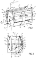
- Figure 1 shows the main parts constituting the internal structure of a toaster according to the invention.
- the toaster comprises a housing 1, preferably metallic including a base 2 connected by its two ends to two lateral flanks 3, 4 and two mesh subassemblies 5, 6, mounted relatively displaceable one opposite the other on the case 1 between the lateral flanks 3,4.
- the two mesh sub-assemblies 5, 6 form between them a mesh slot 7, of plane of symmetry P substantially vertical, said slot being of variable width and able to adapt to the thickness of the article to be toasted by relative displacement of the mesh sub-assemblies 5,6.
- Each mesh sub-assembly 5, 6 comprises a reflector 10, made of a metallic material, having a concavity directed towards the mesh slot 7 so as to be able to reflect the thermal energy in the direction of the article to be grilled.
- At least one of the mesh sub-assemblies 5, 6 comprises in its upper part an edge 11 folded outwards from the toaster.
- Each mesh sub-assembly 5, 6 is also provided with at least one heating element 12 constituted for example by heating bars including a core of refractory material, of the soapstone type, on which a resistive wire is wound.
- the heating elements 12 extend longitudinally in each reflector 10 and are integral with the latter.
- Each grid sub-assembly 5, 6 is completed by a clamping grid 13 delimiting between them the grid slot 7 and joining the upper part of the reflector 10 to its lower part to enclose each heating element 12.
- the clamping grid 13 is intended to grip the items to be toasted such as slices of bread which are inserted in the toasting slot 7.
- a heating element 12 ensuring the toasting by contact and not by radiation, such as a contact plate.
- the clamping grid 13, of the sub-assembly (s) 5, 6 can be omitted.
- the toaster according to the invention also comprises, in known manner, a mobile bread-carrying carriage 15 moving in the toasting slot 7 along its axis, preferably substantially vertically between a high position for receiving the article to be grilled (Figure 2) and a low position for grilling (Figure 3).
- the mobile bread-carrying trolley 15 consisting for example of a metal mesh element, is integral with a displacement control means 16 slidably mounted on a column 17.
- the latter extends substantially vertically along and at outside of the sidewall 3.
- the movement control means 16 is for example constituted by a control carriage 40 provided with an operating arm 16a accessible by the user from outside the housing, in order to be able to operate the mobile bread-carrying carriage 15 axially. .
- the movement control means 16 is associated with an actuation means 19 (FIG. 4) capable of ensuring the relative movement away from or closer to the two mesh sub-assemblies 5, 6.
- the toaster consists of a fixed toasting sub-assembly 5 mounted integral with the housing 1, opposite a movable toasting sub-assembly 6.
- the latter is movably mounted in distance and approximation of the fixed sub-assembly 5 by means of a support 20 comprising on the one hand, two lateral arms 21, 22 extending along the lateral flanks 3,4.
- the lateral arms 21, 22 and preferably their lower ends, are mounted and rotatably supported on the housing 1 around an axis 23.
- the support 20 also includes an intermediate arm 25, forming a pushing or pulling arm, integral with the mobile sub-assembly 6, and joining the two lateral arms 21, 22.
- the support 20 consists of a rod metal folded into a U, so that the two lateral arms 21, 22 and the intermediate arm 25 form a substantially U-shaped support whose intermediate arm 25 extends along and against the upper part of the mobile sub-assembly 6, and advantageously under the fold formed by the edge 11, bearing against the reflector 10.
- each lateral arm 21, 22 can have various shapes and in particular form as shown in Figures 2 and 3, a V extending substantially in a vertical plane.
- the movable mesh sub-assembly 6 is associated with at least one stabilizing arm 30, disposed on the rear face of the reflector 10 and connected by a first articulation 31 to said rear face, and by a second articulation 32 to the housing 1.
- the stabilizer arm 30 is constituted by a metal plate, preferably in the form of a T, the upper bar 33 of which is for example clipped onto the rear face of the reflector 10 in notches, substantially in the central position.
- the lower part of the main branch of the T is preferably secured to the base 2.
- the system for moving the toasting sub-assembly 6 described above is more particularly, but not exclusively, intended to equip toasters of large width, that is to say comprising a toasting slot 7, which, in the position furthest from the two mesh sub-assemblies 5,6, is at least equal to 35 mm, and preferably between 35 and 65 mm.
- Such toasters consequently involve a displacement over a relatively long distance of the subset of movable grilling 6, while allowing the introduction of items to be grilled of large dimensions.
- the movement system of the mobile sub-assembly 6, formed by the support 20 and the stabilizing arm 30, thus constitutes a parallelogram system, in which the arms 21, 22 on the one hand, and the stabilizing arm 30 on the other hand , correspond to mobile connecting rods.
- the distance between the axis of rotation 23 and the arm 25 is as large as possible on the one hand, and the distance between the second articulation 32 and the axis of rotation 23 is also as large as possible on the other hand.
- the vertical movement of the mobile sub-assembly 6 is thus limited, while allowing also limited rotation, of the order of a few degrees, respectively around the axis 23, of the first articulation 31 and of the second articulation 32.
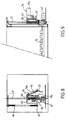
- the means for controlling the movement 16 of the bread-carrying carriage 15 is constituted by a control carriage 40 slidably mounted on the column 17 and displaceable axially and elastically on the latter, relative to the mobile bread-carrying carriage 15 according to a fixed stroke, between a low stop position (FIGS. 4 and 5), in which the mesh sub-assemblies 5, 6 are in operation, and a high elastic return position corresponding to the receiving position of an article to be grilled ( Figures 8 and 9).
- a pole mass 41 fixed under the control carriage 40, comes to lock on an electromagnet 42 integral with the housing 1 in order to close the electrical circuit supplying the heating bars 12.
- the electric delay circuit is then engaged and the heating cycle begins.
- the control carriage 40 is provided with an actuating member 19, such as an actuating finger, the position and size of which allows it, when the control carriage 40 is lowered, to come into contact with a drive ramp 45, integral with the movable mesh sub-assembly 6.
- the drive ramp 45 is formed by a lug having a concavity directed towards the control carriage 40, said lug being integral with one end a lateral arm 21 forming the axis of rotation 23.
- the descent of the control carriage 40 allows the actuating finger 19 to progressively engage the drive ramp 45 so as to impart to it a rotational movement according to the arrow F1, inducing a displacement of the sub- movable assembly 6, in a direction of approach towards the fixed mesh sub-assembly 5.
- the action of the actuating member 19 on the drive ramp 45 maintains the mesh sub-assembly mobile 6 in substantially elastic application against the article to be grilled, by means of the clamping grids 13 and the elasticity of the support 20.
- control carriage 40 is resiliently returned to its position corresponding to the high position for receiving the mobile bread-carrying carriage 15 (FIGS. 6 and 7), by an elastic return member 46, such as a helical spring, interposed between the frame and an external tab 47 of the control carriage 40 and maintaining the control carriage 40 in its high elastic return position.
- an elastic return member 46 such as a helical spring
- the elastic return member 46 may be interposed between the frame and the mobile bread-carrying carriage 15.
- the relative elastic mounting of the control carriage 40, relative to the mobile bread-carrying carriage 15, is advantageously produced by interposing at least one elastic return means 50, preferably a compression spring threaded on the column 17, between the mobile bread-carrying carriage 15 and the control carriage 40.
- the latter is integral with the mobile bread-carrying carriage 15, to form a hitch.
- the control carriage 40 is held in its high elastic return position by the elastic return means 50, the return force of which is preferably greater than that developed by the return member 46, and in the same direction.
- the movable bread-carrying trolley 15 After introduction into the grilling slot 7 of a grilling article of determined width, the movable bread-carrying trolley 15 being in its high receiving position shown in FIGS. 2, 6 and 7, the user manually actuates the operating arm 16a for moving the control carriage 40 downwards, along the column 17.
- the final descent phase first comprises an abutment of the movable bread-carrying carriage 15 corresponding to its low position (FIGS. 8 and 9), then a displacement of the control carriage 40 at the against elastic return means 50 to close the circuit heating and bring the polar mass 41 and the electromagnet 42 into contact ( Figures 4 and 5).
- the actuating finger 19 advantageously consists of a metal pin having an elasticity between its arms 19a, 19b, so as to allow a pressure stress of the mobile sub-assembly 6 against the bread which is adaptable and depends on the thickness said bread.
- the arm 19b is in abutment against one face of the control carriage 40, while the arm 19a is in elastic abutment against the drive ramp 45.
- the elastic return means 50 is gradually constrained, which allows the control carriage 40 to move relative to the bread carriage movable 15 so as to pass from its high elastic return position to its low stop position in which the pole mass 41 is locked on the electromagnet 42. In this position, the time delay is engaged, the electrical resistances of the bars heaters 12 are energized and the pressure of the movable grilling sub-assembly 6 on the article to be grilled is maximum.
- the thrust of the intermediate arm 25 in the upper part of the reflector 10, and over the entire length of the latter, in conjugation with the stabilizing effect in the middle part of the stabilizing arm 30, contributes to an active, balanced movement and free from deformation of said movable mesh sub-assembly 6, whatever the displacement distance considered.
- the electromagnet 42 is no longer supplied and consequently releases the polar mass 41.
- the spring 46 retracts and drives the control carriage 40 to its high position corresponding to the reception position of the mobile bread-carrying carriage 15.
- the elastic return means 50 relaxes and maintains the mobile bread-carrying carriage 15 in its low position, while allowing the control carriage 40 to go back to its high elastic return position.
- the control carriage 40 actuates, by means of the actuating finger 19, the drive ramp 45, initiating a rotation of the latter according to arrow F2 and a pre-disengagement of the movable mesh sub-assembly 6 in a direction opposite to the fixed mesh sub-assembly 5.
- This pre-disengagement is initiated while the carriage is carrying -mobile bread 15 is always in its lowest stop position which avoids any risk of blockage of the article to be toasted due to poor synchronization between all the moving parts.
- control carriage 40 When the control carriage 40 arrives in its high stop position, it then drives, in conjunction with the spring 46, the assembly of the assembly. During this ascent, the actuating finger 19 continues its action on the drive ramp 45, which leads the movable mesh sub-assembly 6 to its extreme rest position corresponding to that shown in FIG. 2, in which the width of the mesh slot 7 is maximum.
- the toaster comprises a fixed bread-carrying carriage 15a, permanently mounted at the bottom of the housing 1.
- the fixed bread-carrying carriage 15a is advantageously mounted substantially opposite the mobile bread-carrying carriage 15 when the latter occupies its low wire position.
- the fixed bread carrier 15a is adjacent to the movable grill sub-assembly 6, while the movable bread carrier 15 is adjacent to the fixed grill sub-assembly 5.
- the removable limitation means 60 is advantageously constituted by a latch mounted on the housing 1, between at least one position for blocking the movement of the movable grid sub-assembly 6 and a release position allowing movement of said sub-assembly over the entire distance H mentioned above. In its blocking position, the latch 60 limits the movement of the mobile sub-assembly 6, in the direction f3, at a distance G, preventing it from returning to its extreme rest position shown in FIG. 2.
- the locking position of the removable means 60 makes it possible to limit the toasting slot 7 to a distance at most equal to a value G less than the distance H and corresponding substantially to the width of the bread-carrying carriage. mobile 15.
- the width of the mobile bread-carrying carriage 15 is substantially equivalent to that of the fixed bread-carrying carriage 15a and corresponds to half the width of the toasting slot 7.
- the distance H will be at most equal at 65 mm and the distance G at most equal to 40 mm and preferably substantially equal to 30-35 mm.
- the toaster with an electric circuit comprising at least two heating powers, corresponding respectively to a toasting mode using the full heating power, and a heating mode using for example simply half the heating power.
- the removable limitation means 60 in a functional manner, with an electrical control switch for the heating powers, so that in the blocking position of the return of the mesh sub-assembly.
- mobile 6 the toasting mode is automatically selected as soon as the electric circuit for controlling the heating bars 12 is closed.
- the removable limiting means 60 makes it possible to automatically select the heating mode. This is particularly interesting, insofar as it turns out that the articles of grilling of large width, are generally not intended to be grilled but on the contrary intended to be reheated.
- Such an inclination of the order of a few degrees, for example from 10 to 15 degrees, must make it possible to create a grid slot 7 inclined in a direction allowing the creation of a permanent return force acting on the movable mesh sub-assembly 6 and therefore on the article to be grilled to direct them towards the fixed mesh sub-assembly 5.
- this corresponds to imparting an inclination of an angle ⁇ of the order of 10 to 15 degrees relative to the vertical V (FIG. 1), to the plane of symmetry P of the mesh slot 7 and to the extension planes of the two mesh subassemblies 5, 6 , this inclination being directed towards the side of the toaster comprising the fixed toasting sub-assembly 5.
- the device forms a mini-oven with variable geometry for food of all kinds whether solid, liquid or pasty, the movable mesh sub-assembly 6 forming the upper closing part of the device.
- the actuating member 19 is an actuating finger, integral with the bread-carrying carriage 15, and capable of engaging a drive ramp 45 in rotation, of the movable mesh sub-assembly 6 , said ramp being linked to the lateral arms 21, 22 or to the stabilizing arm 30.
- the invention finds its industrial application in the manufacture of toasters.
Landscapes
- Engineering & Computer Science (AREA)
- Food Science & Technology (AREA)
- Electric Stoves And Ranges (AREA)
- Baking, Grill, Roasting (AREA)
Claims (10)
- Elektrisches Gerät zum Rösten oder Erwärmen von Nahrungsmitteln, insbesondere Brotröster, mit einem Gehäuse (1), das eine feststehende Röst-Unterbaugruppe (5) sowie eine Röst-Unterbaugruppe (6) aufweist, die von der feststehenden Unterbaugruppe (5) weg oder auf diese zu bewegbar mittels eines Trägers (20) angebracht ist, um einen Röstschlitz (7) mit variabler Breite zu bilden, der sich an die Dicke des zu röstenden Nahrungsmittels anpassen kann, wobei der Träger (20) zwei Seitenarme (21, 22) aufweist, die sich entlang von Seitenteilen der bewegbaren Unterbaugruppe (6) erstrecken und mit ihren Enden an dem Gehäuse (1) drehbar gelagert sind, einem Brot-Trägerschlitten (15), der in dem Schlitz zwischen einer oberen Stellung zur Aufnahme des zu röstenden Nahrungsmittels und einer unteren Röststellung axialverschiebbar angebracht ist, und einem Mittel (16) zur Steuerung der Verstellung des beweglichen Brot-Trägerschlittens (15), das einem Betätigungsorgan (19) zugeordnet ist, welches die Relativverstellung der beiden Unterbaugruppen (5,6) gewährleisten kann, dadurch gekennzeichnet, daß es enthält:- wenigstens einen Stabilisierungsarm (30), der an der Rückseite der beweglichen Unterbaugruppe (6) angebracht ist und durch ein erstes Gelenk (31) mit der Rückseite und durch ein zweites Gelenk (32) mit dem Gehäuse (1) verbunden ist.
- Gerät nach Anspruch 1, dadurch gekennzeichnet, daß der Stabilisierungsarm (30) durch eine vorzugsweise T-förmige Platte gebildet ist.
- Gerät nach Anspruch 1 oder Anspruch 2, dadurch gekennzeichnet, daß der Träger (20) außerdem einen Mittelarm (25) aufweist, der fest mit der beweglichen Unterbaugruppe (6) verbunden ist und die beiden Seitenarme (21, 22) miteinander verbindet.
- Gerät nach Anspruch 3, dadurch gekennzeichnet, daß die beiden Seitenarme (21, 22) und der Mittelarm (25) einen im wesentlichen U-förmigen Träger bilden.
- Gerät nach Anspruch 4, dadurch gekennzeichnet, daß sich der Mittelarm (25) im wesentlichen entlang dem oberen Abschnitt der beweglichen Unterbaugruppe (6) und an diesem in Anlage erstreckt.
- Gerät nach einem der Ansprüche 1 bis 5, dadurch gekennzeichnet, daß das Betätigungsorgan (19) ein Betätigungszapfen ist, der fest mit dem Brot-Trägerschlitten (15) verbunden ist und an einer Betätigungsrampe (45) der beweglichen Röst-Unterbaugruppe (6) durch Drehung angreifen kann, wobei die Rampe mit den Seitenarmen (21, 22) oder dem Stabilisierungsarm (30) verbunden ist.
- Gerät nach Anspruch 6, dadurch gekennzeichnet, daß der Betätigungszapfen (19) durch ein haarnadelförmiges Teil gebildet ist, dessen einer Schenkel (19a) dafür vorgesehen ist, an der Mitnahmerampe (45) in elastische Anlage zu gelangen.
- Gerät nach einem der Ansprüche 1 bis 7, dadurch gekennzeichnet, daß der Röstschlitz (7) in der Stellung, in der die beiden Unterbaugruppen (5, 6) einander am weitesten angenähert sind, wenigstens gleich 35 mm und vorzugsweise zwischen 35 und 65 mm beträgt.
- Gerät nach einem der Ansprüche 1 bis 8, dadurch gekennzeichnet, daß es bezüglich der Horizontalen geneigt ist, so daß eine permanente Rückstellkraft erzeugt werden kann, die auf die bewegliche Unterbaugruppe (6) einwirkt, um diese zur feststehenden Unterbaugruppe (5) zu führen.
- Gerät nach Anspruch 9, dadurch gekennzeichnet, daß die Neigung des Röstschlitzes (7) und der Röst-Unterbauguppen (5, 6) zwischen 10 und 15 Grad beträgt.
Applications Claiming Priority (3)
| Application Number | Priority Date | Filing Date | Title |
|---|---|---|---|
| FR9315667A FR2713908B1 (fr) | 1993-12-21 | 1993-12-21 | Appareil électrique pour le grillage ou réchauffage d'aliments, en particulier grille-pain, à sous-ensembles de grillages déplaçables à l'aide de bras de déplacement. |
| FR9315667 | 1993-12-21 | ||
| PCT/FR1994/001511 WO1995017123A1 (fr) | 1993-12-21 | 1994-12-21 | Appareil electrique pour le grillage ou rechauffage d'aliments, en particulier grille-pain, a sous-ensembles de grillages deplacables a l'aide de bras de deplacement |
Publications (2)
| Publication Number | Publication Date |
|---|---|
| EP0735839A1 EP0735839A1 (de) | 1996-10-09 |
| EP0735839B1 true EP0735839B1 (de) | 1997-12-29 |
Family
ID=9454415
Family Applications (1)
| Application Number | Title | Priority Date | Filing Date |
|---|---|---|---|
| EP95904586A Expired - Lifetime EP0735839B1 (de) | 1993-12-21 | 1994-12-21 | Elektrisches grill- oder wärmegerät für nahrungsmittel, insbesondere brot, mit an beweglichen armen gelagerten rösteinheiten |
Country Status (6)
| Country | Link |
|---|---|
| US (1) | US5653158A (de) |
| EP (1) | EP0735839B1 (de) |
| DE (1) | DE69407623T2 (de) |
| ES (1) | ES2113180T3 (de) |
| FR (1) | FR2713908B1 (de) |
| WO (1) | WO1995017123A1 (de) |
Families Citing this family (22)
| Publication number | Priority date | Publication date | Assignee | Title |
|---|---|---|---|---|
| US6104001A (en) * | 1999-05-25 | 2000-08-15 | Salton, Inc. | Springless adjustable bread guard, and heating appliance including same |
| US6323467B1 (en) * | 1999-07-14 | 2001-11-27 | Philips Electronics North America Corp. | Method and apparatus for selectively applying heat to an object using an addressable array |
| US6250212B1 (en) | 1999-08-20 | 2001-06-26 | The Rival Company | Toaster having carriage-lift mechanism |
| US6380520B1 (en) | 2000-10-25 | 2002-04-30 | Hamilton Beach/Proctor-Silex, Inc. | Toaster with improved safety device |
| ATE319365T1 (de) * | 2000-12-22 | 2006-03-15 | Koninkl Philips Electronics Nv | Brotgrillgerät |
| US6298772B1 (en) | 2001-04-05 | 2001-10-09 | Hamilton Beach/Proctor-Silex, Inc. | Toaster |
| US6486451B1 (en) | 2001-09-21 | 2002-11-26 | Hamilton Beach/Proctor-Silex, Inc. | Toaster chassis assembly with improved safety device |
| CN2512357Y (zh) * | 2001-12-25 | 2002-09-25 | 谭天弘 | 烤面包机的烘焙室 |
| US6708602B2 (en) * | 2002-06-28 | 2004-03-23 | Hamilton Beach/Proctor-Silex, Inc. | Gravity biased grill wires |
| FR2861275B1 (fr) * | 2003-10-24 | 2006-02-10 | Seb Sa | Grille-pain |
| FR2861276B3 (fr) * | 2003-10-24 | 2005-12-30 | Seb Sa | Grille pain |
| US7335858B2 (en) * | 2003-12-18 | 2008-02-26 | Applica Consumer Products, Inc. | Toaster using infrared heating for reduced toasting time |
| US7619186B2 (en) * | 2004-02-10 | 2009-11-17 | Applica Consumer Products, Inc. | Intelligent user interface for multi-purpose oven using infrared heating for reduced cooking time |
| US7323663B2 (en) | 2004-02-10 | 2008-01-29 | Applica Consumer Products, Inc. | Multi-purpose oven using infrared heating for reduced cooking time |
| CN2707036Y (zh) * | 2004-03-11 | 2005-07-06 | 晶辉科技(深圳)有限公司 | 自动式多士炉的启动机构 |
| US7351939B2 (en) | 2004-03-19 | 2008-04-01 | Whirlpool Corporation | Toaster |
| CA2564805A1 (en) * | 2004-04-30 | 2005-11-17 | Salton, Inc. | Electric cooking apparatus having removable heating plates and method for using same |
| CN101401708B (zh) * | 2008-10-31 | 2010-09-08 | 晶辉科技(深圳)有限公司 | 烤面包炉 |
| GB2466954A (en) * | 2009-01-15 | 2010-07-21 | Kenwood Ltd | Variable width toaster |
| USD749349S1 (en) | 2014-11-20 | 2016-02-16 | Hamilton Beach Brands, Inc. | Toaster |
| USD749348S1 (en) | 2014-11-20 | 2016-02-16 | Hamilton-Beach Brands, Inc. | Toaster |
| CN113491454B (zh) * | 2020-04-06 | 2026-04-14 | 尚科宁家运营有限公司 | 能定位在支撑表面上的烹饪系统 |
Family Cites Families (9)
| Publication number | Priority date | Publication date | Assignee | Title |
|---|---|---|---|---|
| US2355153A (en) * | 1941-09-13 | 1944-08-08 | Mcgraw Electric Co | Electric toaster |
| US2788734A (en) * | 1954-03-25 | 1957-04-16 | Gen Electric | Adjustable slot toaster |
| US2910929A (en) * | 1957-01-03 | 1959-11-03 | Westinghouse Electric Corp | Toaster apparatus |
| US3641921A (en) * | 1969-11-14 | 1972-02-15 | Matsushita Electric Industrial Co Ltd | Electric toaster |
| US4188865A (en) * | 1976-06-01 | 1980-02-19 | Bosch-Siemens Hausgerate Gmbh | Electric toaster |
| US4201124A (en) * | 1978-02-27 | 1980-05-06 | Mcgraw-Edison Company | Temperature sensitive timing device for toaster appliance |
| ES2087906T3 (es) * | 1989-02-01 | 1996-08-01 | Seb Sa | Dispositivo para soportar los organos mecanicos y electricos de mando de un tostador de pan y tostador de pan que comprende dicho dispositivo. |
| USD326028S (en) | 1989-07-21 | 1992-05-12 | Seb | Toaster |
| US4976195A (en) * | 1990-05-10 | 1990-12-11 | Cavazos Amado F | Combination bread and tortilla toaster |
-
1993
- 1993-12-21 FR FR9315667A patent/FR2713908B1/fr not_active Expired - Fee Related
-
1994
- 1994-12-21 EP EP95904586A patent/EP0735839B1/de not_active Expired - Lifetime
- 1994-12-21 DE DE69407623T patent/DE69407623T2/de not_active Expired - Fee Related
- 1994-12-21 ES ES95904586T patent/ES2113180T3/es not_active Expired - Lifetime
- 1994-12-21 US US08/666,267 patent/US5653158A/en not_active Expired - Fee Related
- 1994-12-21 WO PCT/FR1994/001511 patent/WO1995017123A1/fr not_active Ceased
Also Published As
| Publication number | Publication date |
|---|---|
| US5653158A (en) | 1997-08-05 |
| DE69407623T2 (de) | 1998-05-28 |
| EP0735839A1 (de) | 1996-10-09 |
| WO1995017123A1 (fr) | 1995-06-29 |
| FR2713908A1 (fr) | 1995-06-23 |
| DE69407623D1 (de) | 1998-02-05 |
| ES2113180T3 (es) | 1998-04-16 |
| FR2713908B1 (fr) | 1996-01-26 |
Similar Documents
| Publication | Publication Date | Title |
|---|---|---|
| EP0735839B1 (de) | Elektrisches grill- oder wärmegerät für nahrungsmittel, insbesondere brot, mit an beweglichen armen gelagerten rösteinheiten | |
| EP0735838B1 (de) | Elektrischer brotröster mit einem betätigungselement mit freihub | |
| EP1430821B1 (de) | Grillvorrichtung oder Vorrichtung zum Aufwärmen von flächen Nahrungsmitteln | |
| EP1395156B1 (de) | Elektrischer toaster | |
| FR2868829A1 (fr) | Four electrique de cuisson ou de chauffage de produits alimentaires supportes par un cadre tournant | |
| EP1525833B1 (de) | Brotroster | |
| CA2337174A1 (fr) | Grille-pain a parois chauffantes transparentes | |
| EP0860132B1 (de) | Brotröster mit Mehrstellungsaufnahmefach | |
| FR2950239A1 (fr) | Grille-pain a porte laterale pivotante | |
| FR2998465A1 (fr) | Dispositif de cuisson pour griller des aliments | |
| EP0381564B1 (de) | Mechanische Vorrichtung zum Verriegeln oder Öffnen des Aufnahmefachs eines Brotrösters | |
| FR2713907A1 (fr) | Grille-pain électrique à double chariot porte-pain. | |
| EP0418336B1 (de) | Vorrichtung zum unterstützen der mechanischen und elektrischen steuerorgane eines brotrösters und brotröster mit einer solchen vorrichtung | |
| EP0845235B1 (de) | Toaster mit einem komplementären System zum Heben des Brotschlittens | |
| EP2401949A1 (de) | Grill | |
| FR2820194A1 (fr) | Four de cuisson electrique a element chauffant pivotant | |
| EP0557221B1 (de) | Brotröster mit geneigter Transportebene | |
| EP0928592B1 (de) | Kochgerät mit einem Griff für eine Kochplatte | |
| FR2960410A1 (fr) | Grille-pain electrique | |
| FR3084927A1 (fr) | Dispositif pour l'extraction automatique d'une grille de four | |
| FR2861275A1 (fr) | Grille-pain | |
| FR3094192A1 (fr) | Dispositif de type grill pour cuire/toaster un aliment équipé d’une résistance noyée | |
| EP1813174A2 (de) | Kochgerät vom Typ Waffeleisen | |
| FR2739273A1 (fr) | Accessoire permettant la preparation de sandwiches tels que par exemple des croque-monsieur |
Legal Events
| Date | Code | Title | Description |
|---|---|---|---|
| PUAI | Public reference made under article 153(3) epc to a published international application that has entered the european phase |
Free format text: ORIGINAL CODE: 0009012 |
|
| 17P | Request for examination filed |
Effective date: 19960619 |
|
| AK | Designated contracting states |
Kind code of ref document: A1 Designated state(s): BE DE ES GB IT NL |
|
| GRAG | Despatch of communication of intention to grant |
Free format text: ORIGINAL CODE: EPIDOS AGRA |
|
| 17Q | First examination report despatched |
Effective date: 19970211 |
|
| GRAH | Despatch of communication of intention to grant a patent |
Free format text: ORIGINAL CODE: EPIDOS IGRA |
|
| GRAH | Despatch of communication of intention to grant a patent |
Free format text: ORIGINAL CODE: EPIDOS IGRA |
|
| GRAA | (expected) grant |
Free format text: ORIGINAL CODE: 0009210 |
|
| AK | Designated contracting states |
Kind code of ref document: B1 Designated state(s): BE DE ES GB IT NL |
|
| REF | Corresponds to: |
Ref document number: 69407623 Country of ref document: DE Date of ref document: 19980205 |
|
| GBT | Gb: translation of ep patent filed (gb section 77(6)(a)/1977) |
Effective date: 19980123 |
|
| ITF | It: translation for a ep patent filed | ||
| REG | Reference to a national code |
Ref country code: ES Ref legal event code: FG2A Ref document number: 2113180 Country of ref document: ES Kind code of ref document: T3 |
|
| PLBE | No opposition filed within time limit |
Free format text: ORIGINAL CODE: 0009261 |
|
| STAA | Information on the status of an ep patent application or granted ep patent |
Free format text: STATUS: NO OPPOSITION FILED WITHIN TIME LIMIT |
|
| 26N | No opposition filed | ||
| PGFP | Annual fee paid to national office [announced via postgrant information from national office to epo] |
Ref country code: NL Payment date: 20001231 Year of fee payment: 7 |
|
| REG | Reference to a national code |
Ref country code: GB Ref legal event code: IF02 |
|
| PG25 | Lapsed in a contracting state [announced via postgrant information from national office to epo] |
Ref country code: NL Free format text: LAPSE BECAUSE OF NON-PAYMENT OF DUE FEES Effective date: 20020701 |
|
| NLV4 | Nl: lapsed or anulled due to non-payment of the annual fee |
Effective date: 20020701 |
|
| PGFP | Annual fee paid to national office [announced via postgrant information from national office to epo] |
Ref country code: BE Payment date: 20041112 Year of fee payment: 11 |
|
| PGFP | Annual fee paid to national office [announced via postgrant information from national office to epo] |
Ref country code: ES Payment date: 20041117 Year of fee payment: 11 |
|
| PGFP | Annual fee paid to national office [announced via postgrant information from national office to epo] |
Ref country code: DE Payment date: 20041208 Year of fee payment: 11 |
|
| PGFP | Annual fee paid to national office [announced via postgrant information from national office to epo] |
Ref country code: GB Payment date: 20041215 Year of fee payment: 11 |
|
| PG25 | Lapsed in a contracting state [announced via postgrant information from national office to epo] |
Ref country code: IT Free format text: LAPSE BECAUSE OF NON-PAYMENT OF DUE FEES Effective date: 20051221 Ref country code: GB Free format text: LAPSE BECAUSE OF NON-PAYMENT OF DUE FEES Effective date: 20051221 |
|
| PG25 | Lapsed in a contracting state [announced via postgrant information from national office to epo] |
Ref country code: ES Free format text: LAPSE BECAUSE OF NON-PAYMENT OF DUE FEES Effective date: 20051222 |
|
| PG25 | Lapsed in a contracting state [announced via postgrant information from national office to epo] |
Ref country code: BE Free format text: LAPSE BECAUSE OF NON-PAYMENT OF DUE FEES Effective date: 20051231 |
|
| PG25 | Lapsed in a contracting state [announced via postgrant information from national office to epo] |
Ref country code: DE Free format text: LAPSE BECAUSE OF NON-PAYMENT OF DUE FEES Effective date: 20060701 |
|
| GBPC | Gb: european patent ceased through non-payment of renewal fee |
Effective date: 20051221 |
|
| REG | Reference to a national code |
Ref country code: ES Ref legal event code: FD2A Effective date: 20051222 |
|
| BERE | Be: lapsed |
Owner name: S.A. *SEB Effective date: 20051231 |