EP0736272A1 - Système d'aménagement - Google Patents
Système d'aménagement Download PDFInfo
- Publication number
- EP0736272A1 EP0736272A1 EP95105158A EP95105158A EP0736272A1 EP 0736272 A1 EP0736272 A1 EP 0736272A1 EP 95105158 A EP95105158 A EP 95105158A EP 95105158 A EP95105158 A EP 95105158A EP 0736272 A1 EP0736272 A1 EP 0736272A1
- Authority
- EP
- European Patent Office
- Prior art keywords
- profile
- elements
- support
- legs
- foot
- Prior art date
- Legal status (The legal status is an assumption and is not a legal conclusion. Google has not performed a legal analysis and makes no representation as to the accuracy of the status listed.)
- Granted
Links
- 239000000463 material Substances 0.000 claims abstract description 6
- 238000005192 partition Methods 0.000 claims description 24
- 238000003032 molecular docking Methods 0.000 claims description 13
- 238000003860 storage Methods 0.000 claims description 5
- 230000002441 reversible effect Effects 0.000 claims description 4
- 239000000725 suspension Substances 0.000 claims description 4
- 230000015572 biosynthetic process Effects 0.000 claims 1
- 239000003086 colorant Substances 0.000 abstract 1
- -1 shapes Substances 0.000 abstract 1
- 230000008901 benefit Effects 0.000 description 5
- 125000006850 spacer group Chemical group 0.000 description 4
- 238000010276 construction Methods 0.000 description 3
- 238000004519 manufacturing process Methods 0.000 description 3
- 239000002184 metal Substances 0.000 description 3
- 240000003085 Quassia amara Species 0.000 description 1
- 230000008859 change Effects 0.000 description 1
- 239000002131 composite material Substances 0.000 description 1
- 230000002349 favourable effect Effects 0.000 description 1
- 238000009434 installation Methods 0.000 description 1
- 238000000034 method Methods 0.000 description 1
- 238000012986 modification Methods 0.000 description 1
- 230000004048 modification Effects 0.000 description 1
- 210000001331 nose Anatomy 0.000 description 1
- 230000001681 protective effect Effects 0.000 description 1
- 238000004080 punching Methods 0.000 description 1
- 230000009467 reduction Effects 0.000 description 1
- 230000007704 transition Effects 0.000 description 1
Images


Classifications
-
- A—HUMAN NECESSITIES
- A47—FURNITURE; DOMESTIC ARTICLES OR APPLIANCES; COFFEE MILLS; SPICE MILLS; SUCTION CLEANERS IN GENERAL
- A47B—TABLES; DESKS; OFFICE FURNITURE; CABINETS; DRAWERS; GENERAL DETAILS OF FURNITURE
- A47B21/00—Tables or desks for office equipment, e.g. typewriters, keyboards
- A47B21/06—Tables or desks for office equipment, e.g. typewriters, keyboards characterised by means for holding, fastening or concealing cables
-
- A—HUMAN NECESSITIES
- A47—FURNITURE; DOMESTIC ARTICLES OR APPLIANCES; COFFEE MILLS; SPICE MILLS; SUCTION CLEANERS IN GENERAL
- A47B—TABLES; DESKS; OFFICE FURNITURE; CABINETS; DRAWERS; GENERAL DETAILS OF FURNITURE
- A47B17/00—Writing-tables
- A47B17/003—Writing-tables made of metal
-
- A—HUMAN NECESSITIES
- A47—FURNITURE; DOMESTIC ARTICLES OR APPLIANCES; COFFEE MILLS; SPICE MILLS; SUCTION CLEANERS IN GENERAL
- A47B—TABLES; DESKS; OFFICE FURNITURE; CABINETS; DRAWERS; GENERAL DETAILS OF FURNITURE
- A47B83/00—Combinations comprising two or more pieces of furniture of different kinds
- A47B83/001—Office desks or work-stations combined with other pieces of furniture, e.g. work space management systems
-
- A—HUMAN NECESSITIES
- A47—FURNITURE; DOMESTIC ARTICLES OR APPLIANCES; COFFEE MILLS; SPICE MILLS; SUCTION CLEANERS IN GENERAL
- A47B—TABLES; DESKS; OFFICE FURNITURE; CABINETS; DRAWERS; GENERAL DETAILS OF FURNITURE
- A47B2200/00—General construction of tables or desks
- A47B2200/0011—Underframes
- A47B2200/0013—Desks with central bearing beams
-
- A—HUMAN NECESSITIES
- A47—FURNITURE; DOMESTIC ARTICLES OR APPLIANCES; COFFEE MILLS; SPICE MILLS; SUCTION CLEANERS IN GENERAL
- A47B—TABLES; DESKS; OFFICE FURNITURE; CABINETS; DRAWERS; GENERAL DETAILS OF FURNITURE
- A47B2200/00—General construction of tables or desks
- A47B2200/0011—Underframes
- A47B2200/002—Legs
- A47B2200/0026—Desks with C-shaped leg
Definitions
- the invention relates to a furnishing system, in particular for offices, according to the preamble of claim 1.
- DE 31 35 576 C2 describes a support structure with a side member of special shape, which forms the basic element of a modular system, but requires very different clamping devices for various upgrade elements. The result is an extremely high manufacturing and assembly effort, although the design options are already limited in terms of design.
- An important aim of the invention is to simplify and at the same time improve the supporting structure of such a system. Its manufacture and assembly should be facilitated while retaining the advantages of proven systems. In addition, the aim is to integrate the power supply as much as possible into the supporting structure, so that convenient connection options go hand in hand with a pleasing appearance.
- the table elements each have a horizontal support with legs and support arms for plates and wherein the support has open longitudinal recesses on a hollow profile on the cross elements such as consoles, plates, strips or the like.
- the invention provides, according to the characterizing part of claim 1, that the profile of the support and the legs has an essentially X-shaped or Y-shaped cross-section and that the longitudinal recesses are trough-shaped outer chambers which are parallel to or inside each other Edge strips run out and can be covered with panels.
- the carrier and the legs have a basic profile of a substantially rectangular shape, between the outer edges of which there are trough-shaped longitudinal recesses which are suitable on the one hand for receiving inserted objects and on the other hand can be covered, so that an externally closed structure appears .
- the consistently uniform profile system allows a variety of connections with the simplest of means, with cross elements such as brackets, plates, strips or the like. can be quickly and securely attached to any type of stand element (table, cabinet, shelf, columns, etc.). Additional suspension rails are unnecessary because the core profile itself can have the required recesses in the chosen grid size.
- One and the same profile element system is sufficient for a wide variety of office furniture, including adjustable elements, and thanks to its uniform functional properties, it is just as suitable for trusses as in the partition wall area.
- the shape of the profile is determined by an inner beam with at least two — preferably four — opposing chambers and with outer surfaces grooved in the longitudinal direction on the edge strips.
- two pairs of outer chambers face each other crosswise.
- the outer surfaces have longitudinal grooves, which not only contribute significantly to the design, but can also perform technical functions, especially for the connection with supporting or transverse elements.
- the trough-shaped outer chambers have undercut longitudinal edges, between which the panels can be fastened, in particular spring-locked.
- These screens can be made of other materials, e.g. B. wood or coated sheet metal, and they can be offset according to claim 4 to the edge strips in material, shape, color and / or pattern, so that they determine the appearance decisively. They make it possible to hide deposits (e.g. cables) in the longitudinal recesses.
- a significant design, for which independent protection is claimed, is characterized according to claim 5, characterized in that supports and legs or posts with the same X profile in the form of L, T and / or angle segments to form linked furniture Units or groups can be connected. This makes it possible to attach the same system elements as support arms, height adjustments, table tops, shelves, cable ducts, etc. to the same base profile and to pull this through during chaining.
- foot brackets are used on the legs or posts below, which have the same shape as attachable upside down on horizontal beams support arms. This greatly simplifies and reduces the cost of warehousing.
- One and the same console can therefore perform one or the other function depending on the installation position. It contributes to the fact that the support arms and foot brackets according to claim 7 on the supports or legs or posts preferably similar docking profiles can be attached, which ensure reliable attachment in a simple manner.
- the local assembly conditions can be taken into account in accordance with claim 8 in that the docking profile has an adjusting piece on which the support arm can be fixed and, for example, can be adjusted with an adjusting bolt. What is important is the embodiment of claim 9, according to which the adjusting piece is designed to be symmetrically reversible, because this further simplifies storage and assembly.
- adjoining corner regions of the support and the supporting leg are mitred.
- the miter surfaces being expediently connected to one another with the interposition of a plate, preferably by means of retaining angles which do not appear to the outside.
- the plate creates a seam-like surrounding edge that covers the miter gap and its burr.
- cables can also be conveniently laid on connections that change direction.
- According to claim 12 can be arranged between mutually associated support arms on locking elements and / or resiliently lockable pan, e.g. can be hung or folded so that filling and emptying can be carried out easily.
- Such a trough allows material to be accommodated which can be stored underneath a table top until use.
- plate brackets with slide guides for an attached extendable table top are provided on mutually parallel support arms, for which claim 14 provides a latching suspension, but which can also be rigidly attached.
- claim 14 provides a latching suspension, but which can also be rigidly attached.
- a frame profile is provided for wall elements which have at least one U-profile for releasable attachment to one another or to a post.
- This allows, for example, partition walls to be connected to table or cupboard elements in a very cost-effective and easy-to-assemble manner, the frame accommodating cross elements which can be fastened with an identical docking piece.
- the frame profile has a trough-shaped, outer chamber which can be covered by a panel and edge strips with longitudinally grooved outer surfaces, the shape and dimensions of the frame profile corresponding in each case to that of a half support or X profile.
- the cross elements can therefore also be attached to partition walls in the same way as to table or cabinet elements, but do not require the entire depth of the base profile.
- the post has, according to claim 17, polygonal adjoining polygonal surfaces, preferably 24 narrow surfaces, on the outer circumference, so that the individual connecting parts can assume predetermined angular positions.
- the 15 ° step provided allows the most varied of spatial requirements to be comfortably taken into account.
- the post in each case forms a node at which it can have an upper end body, such as a flood light, a display panel, a cover, a signpost and the like. Plug-in elements with an electrical connection option are particularly suitable.
- the stability of the assembled arrangement is significantly increased if at least individual legs or posts are each provided with a plate foot or a side support.
- the girders and legs or posts at predetermined grid spacings have recesses for transverse elements, the contact edges or surfaces of which are adapted to the external shape of the profile.
- a column, a hollow box or the like on the support and / or on the pillar or post. can be fastened and locked by means of a lockable panel.
- the column or the box girder serves in particular as an electrical box for accommodating sockets, control devices, telephone and fax connections, power supplies, filters and protective devices, etc.
- the column or the box girder is preferably made of assembled or framed a system profile in the form of mitred parts.
- the lockable cover allows access when needed.
- Claim 24 provides that at least the table and partition elements are electrified, so that only a network connection is required. This measure contributes significantly to minimizing the number and the space requirement of installed cables, because each individual system element - viewed electrically - represents an extension, so to speak.
- the legs and / or the foot extension with e.g. be provided with closable openings for cable routing, so that the otherwise often necessary cable threading is unnecessary; the cables are put through or into the existing recess, which can then be covered by a panel.
- angle plates or the like can also according to claim 26. are used, for example as a footrest.
- claim 27 is very favorable, according to which adjacent table elements can be separated by e.g. Intermediate element designed as an angle segment can be connected, or the like from at least one L or T piece, supporting leg, foot. is supported and this contributes significantly to space saving and cost reduction, especially with linked individual elements.
- the transition in the same or a further plane is made possible by the arrangement of claim 28, wherein angle segments are used which e.g. can be attached to an upper spigot of a carrier can be supported on height-adjustable supports at the front.
- the pin can be a rounded or spherical catch bolt according to claim 29, on which the angle segment can be fixed by means of a snap catch.
- one-piece flat-bottom elements are provided for hanging in vertical holding profiles, in particular on partitions, which have no connecting parts or other loose components such as wire hooks, joints, etc. It is preferred to use flat-bottom elements formed from sheet metal, which have bent side parts and at least one angularly bent longitudinal edge and with hooks at the grid spacing on the back Hook-in recesses are provided. The folds can advantageously be made so that the individual flat-bottom elements can be stacked.
- a taper, groove chamber or the like can be provided on the top and / or on the side surfaces, in particular of wall elements. to be available. This makes it possible to attach appropriate connectors or attachments from above, which not only saves depth, but is also often advantageous for reasons of stability.
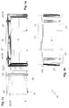
- the table element shown in Fig. 1a, b, c is generally designated 10. It has a horizontal support 12 and two miter legs 13. Attached to this are foot brackets 30, the shape and construction of which may correspond to that of support arms 22 which are attached to the support 12 and hold a table top 20.
- the rear edge defines a rear plane 11, e.g. on a wall (not shown) to which box elements or containers K can also extend.
- the depth thereof preferably corresponds to the depth of the table top 20.
- the carrier 12 has a central bar 14 (FIGS. 3 and 9) with longitudinal outer chambers 15a, 15b, which can accommodate docking profiles 21. With the latter, the support arms 22 or foot bracket 30 are fastened to the support 12 or to the legs 13.
- the support arms 22 are each provided with a plate holder 24 and a slide guide 26, which can optionally be locked and released by a detent spring 25 (FIG. 2). Furthermore, a trough 29 with locking elements 55 can be elastically fixed between mutually associated support arms 22.
- the foot extension 30, like the legs 13, can be provided with height-adjustable stand pieces 31.
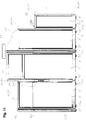
- Fig. 3 and Fig. 9 show the basic shape of a hollow profile P, which is used equally for the carrier 12 as for the legs 13.
- Edge strips 18 connect to a central bar 14 in cross section in an X-shape, the outer surface 19 of which are provided with longitudinal grooves R.
- the profile P has two pairs of outer chambers 15a, 15b, each of which has undercut longitudinal edges 16 towards the outer surface 19.
- a panel 17 (FIG. 3 above) can be inserted between two opposite longitudinal edges or held with a fastening clip 67 (FIG. 9).
- the outer chambers 15a, 15b can differ in shape and size in pairs, so that e.g. two wider outer chambers 15a and narrower outer chambers 15b are diametrically opposed. From Fig. 9 it can be seen how a cable clip 66 is fitted into a wider outer chamber 15a in order to securely fix cables (not shown) guided therein.
- FIG. 3 it is shown on the connecting parts of the support arm 22 how a docking profile 21 of a cross element is received in an outer chamber 15a.
- the docking profile 21 is connected via a spacer plate 54 to an adjusting piece 23, to which the support arm 22 is detachably fastened, specifically by means of a tightening bolt 27.
- the position of the support arm 22 can be readjusted on the adjusting piece 23 with an adjusting bolt 28 if necessary; by turning a threaded pin 57 in or out, the bolt 28 can be displaced to compensate for given tolerances.
- Fig. 3 and Fig. 9 the appearance of the carrier 12 or legs 13 is largely determined by the grooves R on the outer surfaces 19 and grooves Z in the outer chambers 15a, 15b. Both types of longitudinal recesses contribute to stiffening the profile P.
- rows of holes or slots 34 can be provided at a predetermined grid spacing, from which desired transverse elements can be hung.
- FIG. 4a shows that the plate holders 24 of the support arms 22 can have rail-shaped slide guides 26 with optionally operable latching springs 25.
- Fig. 4b and Fig. 4c it can be seen that the attachment of the support arms 22 to the adjusting piece 23 can be done at different heights, so that different working heights can be set without changing the support structure.
- the adjusting pieces 23 can be designed to be symmetrically reversible, but it is also possible and provided according to the invention to design them to be extendable and lockable in a telescopic manner.
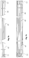
- L-segments, as shown in FIG. 5, and T-segments according to FIGS. 6a, 6b, 6c are particularly advantageous for setting up interlinked furniture elements.
- a shorter leg 48 connects to a supporting leg 13, which can be provided with a standing piece 31 at the bottom, in the upper region by miter. Different types of connection are possible, but miter bonding has proven particularly useful.
- a plate 32 which serves to compensate for any inaccuracies and to cover the miter gap, while tabs or pins 33 and connecting bolts 59 enable the attachment of a connecting element, namely a horizontal support 12.
- Analogous connections to angle segments W can be seen in FIGS. 7a, 7b, 7c.
- bores 53 allow the passage of bolts for connection to various connection elements.
- Holding profiles H can be provided on one or both sides on a table element 10 or 110 or on a partition wall S in order to accommodate hanging parts such as brackets 35 (cf. FIGS. 11 and 12).
- Flat floor elements are well suited 64, which can be made in one piece from sheet metal.
- FIG. 8a shows a basic punching shape which is brought into the shape by simple folding, which is indicated in FIG. 8b and FIG. 8c. It can be seen that such a flat bottom 64 has angled side parts 50 and angled-in longitudinal edges 51, which serve to stiffen and at the same time give the floor 64 the function of a flat trough due to its arching.
- Hooks 52 are provided on the rear on the side parts 50, which allow hooking into the rows of holes or slots 34.
- Such flat bottom elements 64 come without any connecting parts such as screws, rivets, pieces of wire and the like. out. Thanks to the bevels, a high level of stability is achieved even with thinner walls, and the basic shape can also be designed to be stackable.
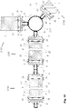
- FIG. 10 (right) is a pillar in the form of a post 113 which has a multiplicity of polygon surfaces, in particular twenty-four narrow surfaces, each offset by 15 ° from one another.
- 10 shows an example with partition walls S arranged at right angles and obtuse angles, each of which connects via a holding profile H to a U-profile 42 screwed to the central post 113 and can be connected to one another via H-profiles 62.
- the docking profiles are expediently designed like longitudinally cut parts of the profile P, the grooves R of which have rows of holes or slots 34 in their base for attaching transverse elements (not shown).
- spacer webs 63 are supported on panels or fillings F, which form the surface parts of the partition walls S or wall elements 40 and can be designed in the desired manner, e.g. with a flat surface in a specific color and / or pattern or with a design structure.
- the holding profiles H have the same grooves R as the profiles P or the frame profiles RP.
- the posts 113 are provided with grooves Z which correspond to those of the outer chambers 15a, 15b.
- FIG. 11 An example of a partition arrangement is shown in FIG. 11.
- the individual partition walls are connected to one another or to wall surfaces by means of U-profiles 42 (not shown here) or by means of posts 113.
- the U-profiles 42 can take on additional functions, for example covering outer chambers 15a, 15b or holding further elements such as busbars (not shown).
- Socket strips 56 can be arranged at the desired height between movable walls S which are rigidly connected in one plane.
- the columns or posts 113 either carry a cover 46 at the top or attached elements such as a flood light 44.
- the partition walls S themselves can carry add-on parts, for example a compensating cover 65.
- display boards 45, signposts or the like can be used. be provided either on a partition S or on a post 113.
- the stability is increased if the columns or posts 113 are each provided with a plate base 47 or a side support 58.
- the wall surfaces of the partition walls S are preferably arranged in a half-profile frame 41, so that frame profiles RP of the shape of half profiles P with their outer chambers 15a, 15b are available for docking transverse elements, for example brackets 35. No full profiles P are required in the partition area, but elements with full profiles P can be docked, inserted or exchanged.
- FIG. 12 shows the example of a layout plan of table elements 110, which can be combined in an extremely varied manner via angle segments W and partition walls S.
- Retaining profiles H like vertically arranged profiles P and posts 113, can take over the necessary intermediate connections. It is important that, in the case of adjacent individual elements, only individual pillars 13 or posts 113 are required in each case thanks to the use of L and T segments.
- cross elements such as brackets, storage shelves, flat bottoms, etc. have been omitted, especially since they are usually hung by the user at different points as required.
- a hollow box (not shown) to the back of a profile P, which can not only accommodate sockets, power supply units, etc., but also control units, surge protection and filter media, as well as telephone and fax as an electrical box and IT connectors.
- an office furnishing system includes various individual pieces of furniture, for example table elements 10, 110 with a horizontal support 12, legs 13 and support arms 22 for panels 20, whereby according to the invention, in hollow trough-shaped outer chambers 15a, 15b of a hollow profile P of X or Y overall cross section different cross elements are dockable.
- panels 17 On undercut longitudinal edges 16, panels 17 that are offset in material, shape, color and / or pattern can be spring-locked.
- the foot bracket 30 and support arms 22 are generally of the same design and preferably have identical docking profiles 21, optionally with a reversible symmetrical adjustment piece 23.
- the corner regions of the support 12 and the support leg 13 are connected to one another at mitred surfaces with the interposition of a plate 32 by holding brackets.
- the supporting structures have the same profile and can be linked to form furniture units or groups, for example by means of L, T and angle segments (W) and by means of posts 113 with a number of narrow surfaces 43 and with a plate base 47 and / or side support 58
- Cross elements which can be suspended in rows of holes or slots 34 can have contact surfaces adapted to the outer shape of the profile P, RP.
Landscapes
- Tables And Desks Characterized By Structural Shape (AREA)
- Joining Of Building Structures In Genera (AREA)
- Tents Or Canopies (AREA)
- Fluid-Driven Valves (AREA)
- Eye Examination Apparatus (AREA)
- Multiple-Way Valves (AREA)
Priority Applications (3)
| Application Number | Priority Date | Filing Date | Title |
|---|---|---|---|
| DE59500605T DE59500605D1 (de) | 1995-04-06 | 1995-04-06 | Einrichtungssystem |
| EP95105158A EP0736272B1 (fr) | 1995-04-06 | 1995-04-06 | Système d'aménagement |
| AT95105158T ATE157514T1 (de) | 1995-04-06 | 1995-04-06 | Einrichtungssystem |
Applications Claiming Priority (1)
| Application Number | Priority Date | Filing Date | Title |
|---|---|---|---|
| EP95105158A EP0736272B1 (fr) | 1995-04-06 | 1995-04-06 | Système d'aménagement |
Publications (2)
| Publication Number | Publication Date |
|---|---|
| EP0736272A1 true EP0736272A1 (fr) | 1996-10-09 |
| EP0736272B1 EP0736272B1 (fr) | 1997-09-03 |
Family
ID=8219165
Family Applications (1)
| Application Number | Title | Priority Date | Filing Date |
|---|---|---|---|
| EP95105158A Expired - Lifetime EP0736272B1 (fr) | 1995-04-06 | 1995-04-06 | Système d'aménagement |
Country Status (3)
| Country | Link |
|---|---|
| EP (1) | EP0736272B1 (fr) |
| AT (1) | ATE157514T1 (fr) |
| DE (1) | DE59500605D1 (fr) |
Cited By (3)
| Publication number | Priority date | Publication date | Assignee | Title |
|---|---|---|---|---|
| EP1110480A1 (fr) * | 1999-11-10 | 2001-06-27 | WH Group Limited | Système de support |
| CN106419092A (zh) * | 2016-11-10 | 2017-02-22 | 泗阳德福来五金制品有限公司 | 一种笔记本电脑桌及其生产方法 |
| US11109670B2 (en) | 2016-10-27 | 2021-09-07 | Steelcase Inc. | Flip top table |
Citations (7)
| Publication number | Priority date | Publication date | Assignee | Title |
|---|---|---|---|---|
| DE2442479A1 (de) * | 1973-09-18 | 1975-03-20 | Roneo Cie | Schwenkeinrichtung fuer einen satz von zwei bis vier vertikalen waenden fuer bueros |
| EP0212679A1 (fr) * | 1985-08-13 | 1987-03-04 | Ahrend Groep B.V. | Piètement pour bureau ou plateau de table |
| DE3744706A1 (de) * | 1987-03-28 | 1988-12-15 | Rose Elektrotech Gmbh | Geraetetraeger fuer computergeraete od. dgl. |
| EP0398014A1 (fr) * | 1989-05-17 | 1990-11-22 | OTTO LAMPERTZ, FABRIKEN FÜR ORGANISATIONSMITTEL UND EDV-ZUBEHÖR GMBH & CO. KG | Système d'ameublement variable pour atelier |
| DE9105491U1 (de) * | 1991-05-03 | 1991-07-25 | Metallwarenfabrik Twick & Lehrke GmbH & Co, 4830 Gütersloh | Aus einem Profilrohr bestehendes Stützbein |
| US5174532A (en) * | 1991-09-06 | 1992-12-29 | Huang Chin Fa | Leg assembly |
| DE4230433A1 (de) * | 1991-10-01 | 1993-04-22 | Mantel Embru Werke | Buerotisch |
-
1995
- 1995-04-06 AT AT95105158T patent/ATE157514T1/de not_active IP Right Cessation
- 1995-04-06 EP EP95105158A patent/EP0736272B1/fr not_active Expired - Lifetime
- 1995-04-06 DE DE59500605T patent/DE59500605D1/de not_active Expired - Fee Related
Patent Citations (7)
| Publication number | Priority date | Publication date | Assignee | Title |
|---|---|---|---|---|
| DE2442479A1 (de) * | 1973-09-18 | 1975-03-20 | Roneo Cie | Schwenkeinrichtung fuer einen satz von zwei bis vier vertikalen waenden fuer bueros |
| EP0212679A1 (fr) * | 1985-08-13 | 1987-03-04 | Ahrend Groep B.V. | Piètement pour bureau ou plateau de table |
| DE3744706A1 (de) * | 1987-03-28 | 1988-12-15 | Rose Elektrotech Gmbh | Geraetetraeger fuer computergeraete od. dgl. |
| EP0398014A1 (fr) * | 1989-05-17 | 1990-11-22 | OTTO LAMPERTZ, FABRIKEN FÜR ORGANISATIONSMITTEL UND EDV-ZUBEHÖR GMBH & CO. KG | Système d'ameublement variable pour atelier |
| DE9105491U1 (de) * | 1991-05-03 | 1991-07-25 | Metallwarenfabrik Twick & Lehrke GmbH & Co, 4830 Gütersloh | Aus einem Profilrohr bestehendes Stützbein |
| US5174532A (en) * | 1991-09-06 | 1992-12-29 | Huang Chin Fa | Leg assembly |
| DE4230433A1 (de) * | 1991-10-01 | 1993-04-22 | Mantel Embru Werke | Buerotisch |
Cited By (4)
| Publication number | Priority date | Publication date | Assignee | Title |
|---|---|---|---|---|
| EP1110480A1 (fr) * | 1999-11-10 | 2001-06-27 | WH Group Limited | Système de support |
| US11109670B2 (en) | 2016-10-27 | 2021-09-07 | Steelcase Inc. | Flip top table |
| US11589672B2 (en) | 2016-10-27 | 2023-02-28 | Steelcase Inc. | Flip top table |
| CN106419092A (zh) * | 2016-11-10 | 2017-02-22 | 泗阳德福来五金制品有限公司 | 一种笔记本电脑桌及其生产方法 |
Also Published As
| Publication number | Publication date |
|---|---|
| EP0736272B1 (fr) | 1997-09-03 |
| ATE157514T1 (de) | 1997-09-15 |
| DE59500605D1 (de) | 1997-10-09 |
Similar Documents
| Publication | Publication Date | Title |
|---|---|---|
| EP0901332B1 (fr) | Systeme modulaire d'amenagement interieur | |
| DE3588159T2 (de) | Arbeitsraumeinteilungssystem | |
| DE69023935T2 (de) | Möbelbausatz. | |
| EP2051605B1 (fr) | Dispositif de presentation de marchandises dote d'un profile dans lequel des supports peuvent etre suspendus | |
| DE69408572T2 (de) | Zusammenbau von dünnen flachen platten | |
| DE2826336C2 (de) | Modulsystem zum Zusammensetzen von Wänden, Schränken, Schreibtischen und/oder anderen zerlegbaren Möbelstücken | |
| DE20002143U1 (de) | Wand-Struktur | |
| DE20121675U1 (de) | Modular aufgebaute Funktionswand | |
| EP0736272B1 (fr) | Système d'aménagement | |
| DE3616732C2 (fr) | ||
| WO2000024981A1 (fr) | Paroi fonctionnelle modulaire | |
| CA2040926C (fr) | Connecteur de cloison d'amenagement de l'espace | |
| DE3129573C2 (de) | Bausatz für Möbel, insbesondere Anbaumöbel | |
| DE9404365U1 (de) | Möbelsystem | |
| DE4411468C2 (de) | Tragsäule für ein Regalsystem | |
| EP0782654B1 (fr) | Systeme d'assemblage, en particulier pour la construction d'unites de rangement et de meubles pre-assembles | |
| DE4415037A1 (de) | Regalanordnung und/oder Schaugestell | |
| DE19624437C1 (de) | Regalgerüst mit verlängerbaren Trägern | |
| EP1075809B1 (fr) | Montant pour rayonnage | |
| CH686966A5 (de) | Universell verwendbare Trenn- bzw. Ausstellungs- oder Praesentationswand. | |
| DE4023807A1 (de) | Wandelbares regalsystem | |
| DE29823223U1 (de) | Bausatz für Läden, Studios u.a. | |
| DE20216360U1 (de) | Möbel-Baukastensystem | |
| DE2546796A1 (de) | Bueromoebel | |
| DE8330113U1 (de) | Raumzelle für Büroinnenräume |
Legal Events
| Date | Code | Title | Description |
|---|---|---|---|
| PUAI | Public reference made under article 153(3) epc to a published international application that has entered the european phase |
Free format text: ORIGINAL CODE: 0009012 |
|
| 17P | Request for examination filed |
Effective date: 19951111 |
|
| AK | Designated contracting states |
Kind code of ref document: A1 Designated state(s): AT BE CH DE DK ES FR GB GR IE IT LI LU MC NL PT SE |
|
| GRAG | Despatch of communication of intention to grant |
Free format text: ORIGINAL CODE: EPIDOS AGRA |
|
| GRAG | Despatch of communication of intention to grant |
Free format text: ORIGINAL CODE: EPIDOS AGRA |
|
| GRAH | Despatch of communication of intention to grant a patent |
Free format text: ORIGINAL CODE: EPIDOS IGRA |
|
| GRAH | Despatch of communication of intention to grant a patent |
Free format text: ORIGINAL CODE: EPIDOS IGRA |
|
| GRAA | (expected) grant |
Free format text: ORIGINAL CODE: 0009210 |
|
| AK | Designated contracting states |
Kind code of ref document: B1 Designated state(s): AT BE CH DE DK ES FR GB GR IE IT LI LU MC NL PT SE |
|
| PG25 | Lapsed in a contracting state [announced via postgrant information from national office to epo] |
Ref country code: NL Free format text: LAPSE BECAUSE OF FAILURE TO SUBMIT A TRANSLATION OF THE DESCRIPTION OR TO PAY THE FEE WITHIN THE PRESCRIBED TIME-LIMIT Effective date: 19970903 Ref country code: IT Free format text: LAPSE BECAUSE OF FAILURE TO SUBMIT A TRANSLATION OF THE DESCRIPTION OR TO PAY THE FEE WITHIN THE PRE;WARNING: LAPSES OF ITALIAN PATENTS WITH EFFECTIVE DATE BEFORE 2007 MAY HAVE OCCURRED AT ANY TIME BEFORE 2007. THE CORRECT EFFECTIVE DATE MAY BE DIFFERENT FROM THE ONE RECORDED.SCRIBED TIME-LIMIT Effective date: 19970903 Ref country code: GR Free format text: LAPSE BECAUSE OF FAILURE TO SUBMIT A TRANSLATION OF THE DESCRIPTION OR TO PAY THE FEE WITHIN THE PRESCRIBED TIME-LIMIT Effective date: 19970903 Ref country code: ES Free format text: THE PATENT HAS BEEN ANNULLED BY A DECISION OF A NATIONAL AUTHORITY Effective date: 19970903 Ref country code: DK Free format text: LAPSE BECAUSE OF NON-PAYMENT OF DUE FEES Effective date: 19970903 |
|
| REF | Corresponds to: |
Ref document number: 157514 Country of ref document: AT Date of ref document: 19970915 Kind code of ref document: T |
|
| REG | Reference to a national code |
Ref country code: CH Ref legal event code: EP |
|
| REF | Corresponds to: |
Ref document number: 59500605 Country of ref document: DE Date of ref document: 19971009 |
|
| GBT | Gb: translation of ep patent filed (gb section 77(6)(a)/1977) |
Effective date: 19971104 |
|
| PG25 | Lapsed in a contracting state [announced via postgrant information from national office to epo] |
Ref country code: SE Effective date: 19971203 Ref country code: PT Effective date: 19971203 |
|
| ET | Fr: translation filed | ||
| REG | Reference to a national code |
Ref country code: IE Ref legal event code: FG4D Free format text: 76270 |
|
| NLV1 | Nl: lapsed or annulled due to failure to fulfill the requirements of art. 29p and 29m of the patents act | ||
| PGFP | Annual fee paid to national office [announced via postgrant information from national office to epo] |
Ref country code: FR Payment date: 19980318 Year of fee payment: 4 |
|
| PG25 | Lapsed in a contracting state [announced via postgrant information from national office to epo] |
Ref country code: LU Free format text: LAPSE BECAUSE OF NON-PAYMENT OF DUE FEES Effective date: 19980406 Ref country code: AT Free format text: LAPSE BECAUSE OF NON-PAYMENT OF DUE FEES Effective date: 19980406 |
|
| PG25 | Lapsed in a contracting state [announced via postgrant information from national office to epo] |
Ref country code: BE Free format text: LAPSE BECAUSE OF NON-PAYMENT OF DUE FEES Effective date: 19980430 |
|
| PGFP | Annual fee paid to national office [announced via postgrant information from national office to epo] |
Ref country code: DE Payment date: 19980508 Year of fee payment: 4 |
|
| PG25 | Lapsed in a contracting state [announced via postgrant information from national office to epo] |
Ref country code: IE Free format text: LAPSE BECAUSE OF NON-PAYMENT OF DUE FEES Effective date: 19980605 |
|
| REG | Reference to a national code |
Ref country code: IE Ref legal event code: FD4D Ref document number: 76270 Country of ref document: IE |
|
| PLBE | No opposition filed within time limit |
Free format text: ORIGINAL CODE: 0009261 |
|
| STAA | Information on the status of an ep patent application or granted ep patent |
Free format text: STATUS: NO OPPOSITION FILED WITHIN TIME LIMIT |
|
| 26N | No opposition filed | ||
| BERE | Be: lapsed |
Owner name: CHRISTMANN & PFEIFER G.M.B.H. & CO. K.G. Effective date: 19980430 |
|
| PG25 | Lapsed in a contracting state [announced via postgrant information from national office to epo] |
Ref country code: MC Free format text: LAPSE BECAUSE OF NON-PAYMENT OF DUE FEES Effective date: 19981031 |
|
| PG25 | Lapsed in a contracting state [announced via postgrant information from national office to epo] |
Ref country code: GB Free format text: LAPSE BECAUSE OF NON-PAYMENT OF DUE FEES Effective date: 19990406 |
|
| PG25 | Lapsed in a contracting state [announced via postgrant information from national office to epo] |
Ref country code: LI Free format text: LAPSE BECAUSE OF NON-PAYMENT OF DUE FEES Effective date: 19990430 Ref country code: CH Free format text: LAPSE BECAUSE OF NON-PAYMENT OF DUE FEES Effective date: 19990430 |
|
| GBPC | Gb: european patent ceased through non-payment of renewal fee |
Effective date: 19990406 |
|
| REG | Reference to a national code |
Ref country code: CH Ref legal event code: PL |
|
| PG25 | Lapsed in a contracting state [announced via postgrant information from national office to epo] |
Ref country code: FR Free format text: LAPSE BECAUSE OF NON-PAYMENT OF DUE FEES Effective date: 19991231 |
|
| REG | Reference to a national code |
Ref country code: FR Ref legal event code: ST |
|
| PG25 | Lapsed in a contracting state [announced via postgrant information from national office to epo] |
Ref country code: DE Free format text: LAPSE BECAUSE OF NON-PAYMENT OF DUE FEES Effective date: 20000201 |